
| PLEASE NOTE: The images presented on this page are of low resolution and, as a result, will not print out very well. If you wish to have higher resolution files then you may purchase them for only $2.95 per patent by using the "Buy Now" button below. All purchases are via PayPal. These files have all been cleaned up and digitally enhanced and are therefore suitable for printing, publication or framing. Each zip package contains all the images below (some packages may contain more), and purchased files can be downloaded immediately. |
UNITED STATES PATENT OFFICE.
_________________
EDWARD O. CARVIN, OF VALLEY SPRINGS, CALIFORNIA,
ASSIGNOR OF ONE-HALF TO T. J. FRENCH, OF SAME PLACE.
BENCH-PLANE.
_________________
SPECIFICATION forming part of Letters Patent No. 659,287, dated October 9, 1900.
Application filed June 14, 1900. Serial No. 20,364. (No model.)
_________________
To all whom it may concern:
Be it known that I, EDWARD O. CARVIN, a citizen of the United States, residing at Valley Springs, in the county of Calaveras and State of California, have invented certain new and useful Improvements in Planes; and I do hereby declare the following to be a full, clear, and exact description of the invention, such as will enable others skilled in the art to which it appertains to make and use the same.
This invention relates to carpenters’ planes, and more particularly to the means whereby the handle is susceptible of adjustment to a variety of positions to meet diiferent conditions to facilitate the work and secure ease and comfort to the workman.
The improvement consists of the novel features and the details of construction, which hereinafter will be more fully set forth, and finally pointed out in the appended claims.
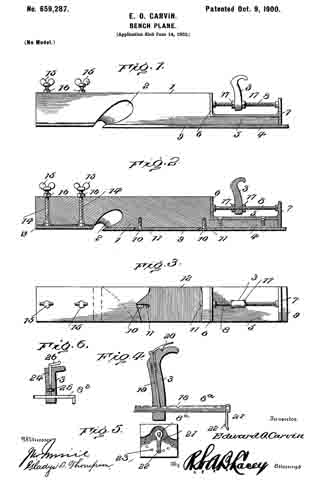
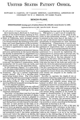
In the drawings, Figure 1 is a side elevation of a plane constructed in accordance with and embodying the essential features of the invention. Fig. 2 is a central longitudinal section thereof. Fig. 3 is a top plan view, parts being broken away. Fig. 4 is a detail view showing different mountings for the handle. Fig. 5 is an end view of the construction shown in Fig. 4. Fig. 6 is a detail view showing different means for securing the handle in an adjusted position.
Corresponding and like parts are referred to in the following description and indicated in all the views of the drawings by the same reference characters.
The body 1 of the plane may be of any size and pattern, according to the style of plane, and is provided with a throat 2, adapted to deliver the shavings at one side of the plane, said throat extending transversely of the body and flaring from one side thereof to the other. The rear or heel portion of the body is reduced in depth to enable the handle 3 to be as low down as possible, and the heel portion 4 is reinforced by a horizontal plate 5, secured thereto and provided at its ends with vertical extensions 6 and 7, the latter projecting above and below the plate 5, as shown, the upper extension receiving the rear end of the handle-support 8 and the lower extension overlapping the rear end of the heel portion 4. The parts 5, 6, and 7 are of integral formation and are secured to the parts of the body in any substantial manner. The bit 9 is secured to the lower face of the body 1 in the rear of the throat 2 and is adjustable longitudinally to compensate for wear incident to sharpening. Clamp-screws 10 are let into the body 1 and their heads fit countersunk portions of longitudinal slots 11, formed in the bit, so as not to project beyond the lower face thereof. After the bit has been properly positioned it is secured by tightening the clamp-screws 10, and in order to prevent possible slipping of the bit the latter is formed upon its top side or the face adapted to lie adjacent to the lower side of the body 1 with transverse serrations or Iine teeth 12, which bite into the face of the body and positively hold the bit in the adjusted position after the clamp-screws have been properly tightened. The bit 9 protects the lower face of the body 1 and by being disposed in the manner set forth operates by a more direct cut, whereby knots and timber are adapted to be readily cut across grain.
In order to regulate the depth of out or thickness of shaving, a gage-plate 13 is located in advance of the throat 2 and is vertically adjustable, any suitable means being employed to effect this result, and, as shown, companion set-screws let are threaded into the body of the plane and make swivel connection at their lower ends with bosses provided upon the top side of the gage-plate 13, said set-screws being adapted to be turned by means of thumb-buttons 15 at their upper ends. Jam-nuts 16 are fitted to the set-screws 14 to hold the latter in the required position. By turning the set-screws either to the right or to the left the gage-plate can be lowered or raised, according to the desired thickness of shaving to be cut.
The handle-support 8 is a rod or bar centrally disposed with reference to the body 1 and secured at its ends to the vertical extensions of the plate 5. The handle 3 is adjustable on the support 8, so as to be brought nearer to the cutting edge of the bit or farther away therefrom, according to the nature of the work and the convenience to the user. The handle, in addition to its longitudinal adjustment with reference to the plane, can be turned to any desired angular position either to the rightor to the left, thereby enabling the plane to be used in angles and close quarters, where it would be inconvenient to grasp the handle and manipulate the plane if said handle occupied a vertical position. Any means may be employed for securing the handle in the required position, and, as shown in Figs. 1, 2, and 3, a pair of nuts 17 is mounted upon the rod 3, which latter is screw-threaded throughout its length, the handle 3 being clamped between the nuts of the pair.
In the construction shown in Figs 4 and 5 the rod or bar 8a is formed in a side with a series of openings 18, and the handle 3 is provided with a spring-actuated pin 19 to enter any one of the openings 18 and hold the said handle in an adjusted position, the pin 19 being operated by means of a thumb-latch 20, pivoted to the offset portion of the handle. This support 8a is mounted in the vertical extensions of the plate 5 so as to turn and is provided at its rear end with a spring-arm 21, provided with a stud 22 to enter one of a series of openings 23, formed in the rear face of the vertical extension 7, whereby the handle is positively secured when turned either to the right or to the left from a vertical position. The construction is such as to admit of the body 1 being formed of wood, the plate 13 and the bit 9 forming a metal surface for the lower side thereof to protect it from wear and injury. The depression of the bit enables it to operate by a more direct cut, whereby it will pass more easily through knotty wood and across grain without disturbing the fibrous structure of the material to such an extent as to leave a rough surface commonly experienced when dressing knotty timber by planes of ordinary construction. In the event of the body 1 being of metal or other material the plate 13 and the bit 9 form a facing therefor.
Fig. 6 shows the handle 3 mounted upon a smooth rod 8b and provided with a clamp device consisting of rod 24, having its inner end portion threaded to coact with a nut 25, let into the handle and having its outer end bent, as at 26, to form a grip for turning the rod to release or secure the handle.
Having thus described the invention, what is claimed as new is —
1. In combination with a carpenter’s plane, a handle adjustable lengthwise of the plane and to any angular position, and means for securing the handle in an adjusted position, substantially as set forth.
2. A carpenter’s plane having its rear portion rednced upon its top side for a short distance from its rear end, a support disposed parallel of the plane and located above the heel thereof, and a handle adjustably mounted upon the said support, substantially as specified.
3. In combination with a carpenter’s plane, a support mounted so as to be turned about its axis, means for turning said support and securing it in an adjusted position, and a handle adjustable on the said support, substantially as specified.
In testimony whereof I affix my signature in presence of two witnesses.
EDWARD O. CARVIN. [L. S.]
Witnesses:
JAMES B. LUDDY,
F. J. SOLINSKY.