
| PLEASE NOTE: The images presented on this page are of low resolution and, as a result, will not print out very well. If you wish to have higher resolution files then you may purchase them for only $2.95 per patent by using the "Buy Now" button below. All purchases are via PayPal. These files have all been cleaned up and digitally enhanced and are therefore suitable for printing, publication or framing. Each zip package contains all the images below (some packages may contain more), and purchased files can be downloaded immediately. |

UNITED STATES PATENT OFFICE.
_________________
MASCHIL D. CONVERSE, OF NEW YORK, N. Y.,
ASSIGNOR TO JOHN J. TOWER, OF SAME PLACE.
PLANE.
_________________
SPECIFICATION forming part of Letters Patent No. 661,010, dated October 30, 1900.
Application filed March 19, 1900. Serial No. 9,276. (No model.)
_________________
To all whom it may concern:
Be it known that I, MASCHIL D. CONVERSE, a citizen of the United States, residing in the city of New York, borough of Manhattan, county of New York, and State of New York, have invented certain new and useful Improvements in Planes, of which the following is a specification.
My invention relates to planes, and more particularly to adjustment mechanisms for the bits or irons thereof.
In planes constructed with clamp-plates and cramp-screws for securing the bit, more especially in those in which the end of the cramp-screw engages the surface of the bit, of which Letters Patent No. 619,394 is an example, it has been found that the point or end of the cramp-screw so indents and mars the surface of the bit that when it is desired to loosen the latter for adjustment the marred surface frequently interferes by either requiring the said cramp-screw to be so much loosened (to free the point or end of the indentations) that efforts to adjust the bit in one direction (either longitudinally or laterally) will cause the other adjustment to be lost or when retightening the cramp-screw its end will slip back again into the indentation or marrings on the bit’s surface, so that the desired adjustment is not with facility and certainty attained.
The objects of my present invention are not only to overcome these difficulties, but to provide a lateral adjustment mechanism which shall be adapted for use also in convertible planes of the type shown in Letters Patent No. 620,226 or analogous ones in which clamp-plates and cramp-screws essentially of the same character as hereinbefore referred to are employed, but in which the end of the cramp-screw instead of engaging the surface of the bit engages a slide or a socket in a slide, and the further object is to provide an inexpensive, simple, and efficient lateral adjustment device that may be expeditiously operated.
To these ends my invention consists in the several particulars of construction, arrangement, and combination of parts severally and more particularly hereinafter pointed out and claimed.
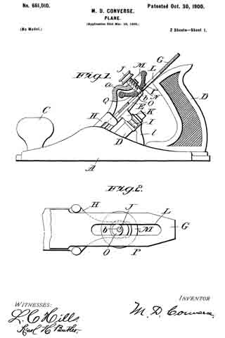
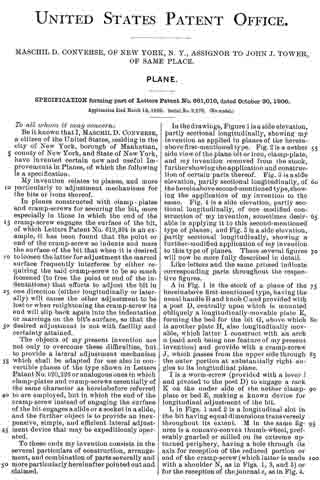
In the drawings, Figure 1 is a side elevation, partly sectional longitudinally, showing my invention as applied in planes of the herein-above first-mentioned type. Fig. 2 is a nether side view of the plane bit or iron, clamp-plate, and my invention removed from the stock, further showing the application and construction of certain parts thereof. Fig. 3 is a side elevation, partly sectional longitudinally, of the hereinabove second-mentioned type, showing the application of my invention to the same. Fig. 4 is a side elevation, partly sectional longitudinally, of one modiiied construction of my invention, sometimes desirable in applying it to this second-mentioned type of planes; and Fig. 5 is a side elevation, partly sectional longitudinally, showing a further-modified application of my invention to this type of planes. These several figures will now be more fully described in detail.
Like letters and the same primed indicate corresponding parts throughout the respective figures.
A in Fig. 1 is the stock of a plane of the hereinabove first-mentioned type, having the usual handle B and knob C and provided with a post D, centrally upon which is mounted obliquely a longitudinally-movable plate E, forming the bed for the bit G, above which is another plate H, also longitudinally movable, which latter I construct with an arch a (said arch being one feature of my present invention) and provide with a cramp-screw J, which passes from the upper side through the outer portion at substantially right angles to its longitudinal plane.
I is a worm-screw (provided with a lever l and pivoted to the post D) to engage a rack K on the under side of the nether clamp-plate or bed E, making a known device for longitudinal adjustment of the bit.
L in Figs. 1 and 2 is a longitudinal slot in the bit having equal dimensions transversely throughout its extent. M in the same figures is a concave-convex thumb-wheel, preferably gnarled or milled on its extreme upturned periphery, having a hole through its axis for reception of the reduced portion or end of the cramp-screw (which latter is made with a shoulder N, as in Figs. 1, 3, and 5) or for the reception of the journal e, as in Fig. 4. This thumb-wheel is provided with an eccentric O, (which I prefer to be integral,) extending from the convex side to enter the slot L and engage the lateral parallel walls thereof. The diameter of this eccentric should be so nearly equal the transverse measurement of the slot L as barely to slide freely therein. The surface immediately surrounding the eccentric radially on the convex side of the thumb-wheel at P, I level or flatten in order that the same may have a considerable area for engagement with the upper side of the plane-bit G by overhanging the lateral margins of the slot L. The arch ct of the clamp-plate H is for the accommodation of the upturned periphery of the thumb-wheel, which latter is so made in order that it may be accessible to the thumb and finger of the operator.
At Q it will be seen that the hole in the axis of the thumb-wheel on the convex side is countersunk and that a portion of the reduced pivot or pivot end is upset at b, so as to prevent the said thumb-wheel from becoming separated from the clamp-plate H when the bit is being removed.
Those skilled in the art will now see that in the operation of my invention the upturned periphery of the thumb-wheel gives convenient access (as before stated) for its manipulation by the thumb and finger of the operator, a construction for the thumb-wheel made possible when placed below the clamp-plate H by the arch a of the latter, that turning the thumb-wheel to either the right or left will accomplish lateral adjustment of the bit, and that the overhanging radially-extended flattened surface of the convex side of the thumb-wheel at P offers an area of sufficient extent to prevent indentation or marring of the surface of the bit, which it engages when the cramp-screw J is tightened, and because the point or end of the cramp-screw is not employed to engage the bit, but its pressure is communicated to the latter by means of the shoulder N, through the thumb-wheel, the under or convex side of which latter bears upon and binds the bit, except in the modification shown by Fig. 4, where the journal or pivot of the thumb-wheel and eccentric is independent of the cramp-screw and is not axially coincident therewith, which cramp-screw, however, in such case does not engage the surface of the bit, but engages a slide or a socket in a slide, as before mentioned, while in the modification shown by Fig. 5 a stud S is fixed in the clamp-plate to engage the socket in the slide (but without pressure on the bottom of the socket) instead of the cramp-screw. The advantages of the device of an arched clamp-plate H, with a thumb-wheel of the form described, will also be readily seen by such both on account of great economy of manufacture (since they severally may be cast in integral parts) and greater efficiency and convenience in operation.
I do not herein claim, broadly, the application of a lateral bit-adjustment mechanism to have its fulcrum coincident to the axis of the cramp-screw, such having been claimed and allowed to me in Letters Patent No. 619,394, dated February 14, 1899, nor do I wish to limit myself in my present invention to a combination with the cramp-screw as a pivotal axis therefor, since manifestly the improved form and construction of the leading features of my present invention adapt it to be employed on an independent pivot similarly to that shown in Fig. 4.
Having described my invention, what I do claim as new, and desire to secure by Letters Patent, is —
1. In a plane a lateral bit-adjustment mechanism comprising an arched clamp-plate carrying a pivot and cramp-screw, a concavo-convex thumb-wheel revolubly mounted on said pivot, provided with an eccentric on its convex side and a radially-flattened surface thereon adjacent to said eccentric, in combination with a longitudinally-slotted bit.
2. In a plane a lateral bit-adjustment mechanism comprising an arched clamp-plate carrying a shouldered pivot and cramp-screw, a concavo-convex thumb-wheel revolubly mounted on said pivot, provided with an eccentric on its convex side and a radially-flattened surface thereon adjacent to said eccentric, in combination with a longitudinally-slotted bit.
3. In a plane a lateral bit-adjustment mechanism comprising an arched clamp-plate carrying a pivot and cramp-screw, a concave-convex thumb-wheel revolubly mounted on said pivot, provided with an eccentric on its convex side and a radially-flattened surface thereon adjacent to said eccentric and means for preventing the said thumb-wheel from becoming accidentally detached from said clamp-plate, in combination with a longitudinally-slotted bit.
In testimony whereof I afiix my signature in presence of two witnesses.
MASCHIL D. CONVERSE.
Witnesses:
H. S. WELCH,
FRANK A. JONES.