
| PLEASE NOTE: The images presented on this page are of low resolution and, as a result, will not print out very well. If you wish to have higher resolution files then you may purchase them for only $2.95 per patent by using the "Buy Now" button below. All purchases are via PayPal. These files have all been cleaned up and digitally enhanced and are therefore suitable for printing, publication or framing. Each zip package contains all the images below (some packages may contain more), and purchased files can be downloaded immediately. |

UNITED STATES PATENT OFFICE.
_________________
EDWARD S. MARKS, OF AUBURN, NEW YORK,
ASSIGNOR TO OHIO TOOL COMPANY, OF NEW YORK.
PLANE.
_________________
SPECIFICATION forming part of Letters Patent No. 680,055, dated August 6, 1901.
Application filed December 4, 1900. Serial No. 38,705. (No model.)
_________________
To all whom it may concern:
Be it known that I, EDWARD S. MARKS, a citizen of the United States, and a resident of the city of Auburn, in the county of Cayuga and State of New York, have invented certain new and useful Improvements in Planes, of which the following is a specification.
This invention consists in certain new devices used to regulate the position of the chisel in relation to the plane-stock; and its object. is to furnish means for readily adjusting the chisel both longitudinally and laterally.
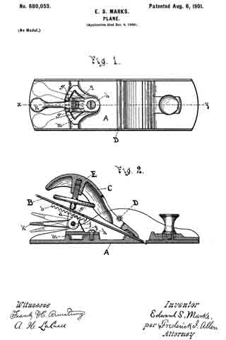
In the drawings, Figure 1 is a plan of a plane provided with my improvements and with the chisel and retaining-cap removed; and Fig. 2 is a sectional view upon the line x y of Fig. 1, showing the chisel and cap in position.
Similar reference-letters indicate like parts in both views.
In the drawings, A is the plane-stock, B is the chisel, and C the cap-iron, which is secured under the cross-bar D by means of the screw E.
The chisel B is provided with a rack b, and a pinion-section d, pivoted at f and operated by a lever K, engages it. The dotted lines of Fig. 2 indicate different positions which this lever may occupy in the vertical plane. By this means the chisel is moved in the direction of its length as required.
The carriage g, which supports the pivot f, is pivotally secured at h, so that it may be moved laterally, and the dotted lines of Fig. 1 show dilierent positions which it may occupy in the horizontal plane, the upright ears g’, rising from the carriage g, straddling the rack b on the under side of the chisel B and lengaging the parts for lateral adjustment, as shown in Fig. 2, the segment m upon the plane-stock furnishing a support for it in its different positions.
By the above-described means the chisel B is readily adjusted either vertically or laterally, as desired.
What I claim as new, and desire to secure by Letters Patent, is —
1. In a plane and in combination, a plane-stock, a chisel, means for clamping said chisel in said plane-stock, a carriage having a vertical pivotal connection with said plane-stock, a lever carried by and having a horizontal pivotal connection with said carriage to shift said carriage laterally on its pivot, means on said carriage to engage and shift said chisel laterally, and means on said pivoted carriage-lever to engage said chisel and shift it longitudinally.
2. In a plane and in combination, a plane-stock, a chisel, means for clamping said chisel in said plane-stock, a carriage having a vertical pivotal connection vvith said plane-stock, a segment formed on said stock to support said carriage, a lever carried by and having a horizontal pivotal connection with said carriage to shift said carriage laterally on its pivot, upright ears on said carriage to engage and shift said chisel laterally, and means on said pivoted carriage-lever to engage said chisel and shift it longitudinally.
Signed at Auburn, New York, this 1st day of December, A. D. 1900.
EDWARD S. MARKS.
Witnesses:
HENRY D. PARSELL,
FREDERICK I. ALLEN.