| PLEASE NOTE: The images presented on this page are of low resolution and, as a result, will not print out very well. If you wish to have higher resolution files then you may purchase them for only $2.95 per patent by using the "Buy Now" button below. All purchases are via PayPal. These files have all been cleaned up and digitally enhanced and are therefore suitable for printing, publication or framing. Each zip package contains all the images below (some packages may contain more), and purchased files can be downloaded immediately. |
UNITED STATES PATENT OFFICE.
_________________
GEORGE G. DENNIS, OF MANCHESTER, NEW HAMPSHIRE, ASSIGNOR OF
ONE-HALF TO GEORGE A. DOLBER, OF MANCHESTER, NEW HAMPSHIRE.
BENCH-PLANE GUIDE.
_________________
SPECIFICATION forming part of Letters Patent No. 701,471, dated June 3, 1902.
Application filed September 9, 1901. Serial No. 74,761. (No model.)
_________________
To all whom it may concern:
Be it known that I GEORGE G. DENNIS a citizen of the United States, residing at Manchester, in the county of Hillsboro and State of New Hampshire, have invented certain new and useful Improvements in Bench-Plane Guides; and I do declare the following to be a full, clear, and exact description of the invention, such as will enable others skilled in the art to which it appertains to make and use the same, reference being had to the accompanying drawings, and to the letters of reference marked thereon, which form a part of this specification.
This invention relates to improvements in bench-plane guides and contemplates a simple and durable guide adapted to be readily attached to iron planes and which in use is very efficient and is not liable to disorder.
The nature of my invention will be readily comprehended, reference being had to the following detailed description and to the accompanying drawings, in which —
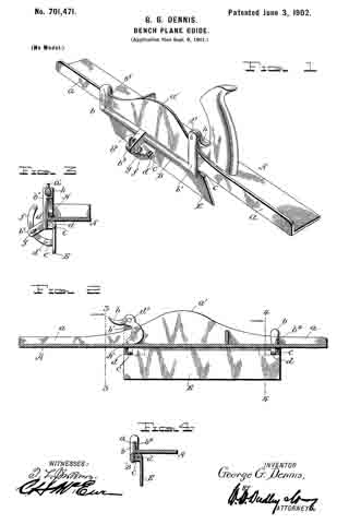
Figure 1 is a perspective view of my improved guide attached to a plane. Fig. 2 is a longitudinal sectional view of the plane and an elevation of the attached guide. Fig. 3 is a cross-sectional view on line 3 3 of Fig. 2. Fig. 4 is a cross-sectional view on line 4 4 of Fig. 2.
Referring to the drawings by letter, A denotes an iron bench-plane, which may be of the usual construction. At one side of the plane is the usual vertical flange a, having an intermediate enlargement a’.
My improved guide is comprised of a frame B, having at its ends vertical extensions b b’ and an intermediate outwardly-projecting lug b2. At the rear side and toward the ends of the frame B are ears c c, apertured to receive pins d d, which pivotally connect to the frame the adjustable guide-plate E. The guide plate has at its outer side and centrally a slotted and apertured ear c’, to which is pivotally connected by a pin d’ one end of an arm f The other end of the arm occupies a slot b3 in the lug b2, and g is a thumb-nut, which is screwed into the lug against the arm to maintain the adjustment of the guide-plate.
The extension b is provided at its upper end with a return bend b4, which hooks over the flange a. To the upper end of the extension b is pivotally secured, by means of a pin d2, a cam H, having a handle h.
In attaching the guide to the plane the frame is slid toward the rear until the forward rise of the flange enlargement wedges tightly between the hook b and the forward ear c The cam is then turned to tightly clamp the body of the plane between it and the rearward ear c The guide is thus easily and quickly attached and detached and when in place is firmly held against movement.
I claim as my invention —
A guide for flanged bench-planes consisting of a frame having at one end an extension terminating in an integral hook to engage the flange, an extension at the other end of the frame, a cam pivoted on the latter extension adapted to clamp the body of the plane, ears on the frame, a guide-plate pivoted to the ears, a pivoted arm on the guide-plate adjustable in a slot in a lug on the frame, and a set-screw passed through the lug against the arm for maintaining the adjustment.
In testimony whereof I affix my signature in presence of two witnesses.
GEORGE G. DENNIS.
Witnesses:
GEO. W. PRESCOTT,
FRED T. DUNLAP.


