
| PLEASE NOTE: The images presented on this page are of low resolution and, as a result, will not print out very well. If you wish to have higher resolution files then you may purchase them for only $2.95 per patent by using the "Buy Now" button below. All purchases are via PayPal. These files have all been cleaned up and digitally enhanced and are therefore suitable for printing, publication or framing. Each zip package contains all the images below (some packages may contain more), and purchased files can be downloaded immediately. |
UNITED STATES PATENT OFFICE.
_________________
ALIX W. STANLEY AND HENRY S. WALTER, OF NEW BRITAIN, CONNECTICUT, ASSIGNORS TO
STANLEY RULE & LEVEL COMPANY OF NEW BRITAIN CONNECTICUT, A CORPORATION OF CONNECTICUT.
PLANE.
_________________
SPECIFICATION forming part of Letters Patent No. 703,158, dated June 24, 1902.
Application filed December 27, 1901. Serial No. 87,500. (No model.)
_________________
To all whom it may concern:
Be it known that we, ALIX NV. STANLEY and HENRY S.WALTER, citizens of the United States, residing at New Britain, county of Hartford, State of Connecticut, have invented certain new and useful Improvements in Planes, of which the following is a full, clear, and exact description.
Our invention relates to improvements in the construction of planes.
The object of our invention is to provide a simple, inexpensive, and effective means for securing in place the means whereby the position of the cap of the plane is determined, as will he understood from the following description, taken in connection with the accompanying drawing.
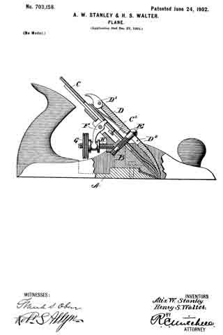
In the illustration we have shown a side elevation of a plane fitted with an embodiment of our improved construction, parts of the plane being seen in section.
The plane which we have chosen to here describe is an iron plane, in which A is the bottom.
B is what is commonly termed the “frog” of the plane. This frog B is secured to the base and presents an inclined upper surface leading down to the slot in the base A, through which the plane-iron C projects. In this type C’ is a plane-iron cap, the two parts thus forming a double plane-iron. The iron C furnishes the cutting edge.
D is what is termed the “cap.” In the particular construction shown this cap is provided with a cam D’.
E is what is termed the “cap-screw” or “holder.” This part E is ordinarily in the form of a headed screw, which takes into a tapped hole in the frog B. This holder E is seldom if ever adjusted after it has been secured in its proper position, and it is desirable to have it snugly retained in that position, so that it will not work loose and disturb the adjustment or allow chattering of the parts when in use. At the same time it is desirable not to have a permanent connection in order that in the event of an emergency a new holder can be inserted. In case the cap should become broken or lost a new cap must be inserted, and if it should vary slightly in dimensions from the original cap the holder must be adjusted. It will therefore be seen that an adjustable cap-screw that will not become loose or accidentally disturbed from its proper position is the end which we seek to attain.
F is a lever or Y adjustment pivoted to the frog B, one end of which is adapted to engage with the plane-iron C, the other end being engaged by an adjusting-nut G. This nut or thumb-nut G is movable on a screw or post H, also carried by the frog B. The plane-iron may be advanced or retracted relatively to the bottom of the plane by means of the adjusting-nut G, which operates the lever F, engaging with the plane-iron, regulating the depth of the cutting edge in the usual manner.
Our invention will be found to consist in so arranging the screw-threaded or tapped passages in the frog B for the cap-screw E and the post H that the said passages intersect for the purpose of permitting the post H to be set up against the holder or cap-screw E when the latter is in its proper position.
We thus securely lock the parts in place to prevent their becoming accidentally displaced or loosened. The screw or post H therefore performs a double function. Not only is it a means for supporting the thumb-nut G for the adjustment of the plane-iron, but it also forms the locking means for the cap-screw or holder. In our preferred construction the thread of the screw E, adjacent the point where the end of the screw H is to engage and lock the same, is turned down, so as to remove the screw-threads. Consequently the end of the screw H will not batter the screw E and render it difficult or impossible to operate it when desired. Furthermore, by so doing a better bearing-face is afforded for the end of the locking screw or post H. Heretofore the frictional engagement of the screw-threads of the cap-screw E has been solely relied upon as the means for holding the screw in position.
By our improvement a simple, inexpensive, and effective means is provided whereby if the frictional engagement of the screw-threads is insufficient the movement of the cap~screw is nevertheless prevented.
The assembling of the plane is accomplished in the well-known manner, there being nothing to require special instructions in regard thereto. The plane-iron is inserted in the usual way, and the cap D is placed thereon, a keyhole-opening D2 in the cap allowing the cap to be slipped on over the holder E. It is then slid down into place, so that the head of the screw or holder E will stand over and engage the cap D. The cam D’ is then swung down into the position shown, and thus securely clamps the parts together. Should the cap-screw E become loose, the plane-iron or parts associated therewith will be likely to chatter, producing unevenness and other undesirable results in the work performed. This is entirely avoided by the employment of our invention.
It should be obvious that the improvements in the construction herein set forth are applicable to many different styles of planes, wood as well as iron, and that the bearing for the plane-iron instead of being a separate frog might be made an integral part of the plane itself, also that the particular form and arrangement are not material so long as the combination of cap-screw and post H is such that the latter element performs the double function of supporting the thumb-nut G and securing the cap-screw effectively in place.
What we claim, and desire to secure by Letters Patent, is —
1. In a plane, a plane-iron, a bearing therefor, a cap-screw for holding said plane-iron in engagement with said bearing, an adjusting-screw for regulating the position of said plane-iron, said adjusting-screw also engaging said cap-screw to lock it, substantially as described.
2. In a plane, a plane-iron, a cap-screw for holding said plane-iron in position, an adjusting-nut, a screw therefor, said screw engaging said cap-screw, substantially as described.
3. In a plane, a plane-iron, a cap-screw for holding said plane-iron in position, a portion of the thread on said cap-screw being turned down, a separate screw engaging the turned-down portion of said cap-screw, and an adjusting-nut mounted upon said separate screw, and means coacting with said adjusting-nut for shifting the position of the plane-iron without disturbing the adjustment of the cap-screw.
4. In a plane, a holding-screw E set into the frog B, an adjusting-nut working on a screw H, said screw engaging said holder to lock it in position, substantially as described.
Signed at New Britain, Connecticut, this 5th day of December, 1901.
ALIX W. STANLEY.
HENRY S. WALTER.
Witnesses:
CHAS. B. STANLEY,
ROBT. N. PECK.