
| PLEASE NOTE: The images presented on this page are of low resolution and, as a result, will not print out very well. If you wish to have higher resolution files then you may purchase them for only $2.95 per patent by using the "Buy Now" button below. All purchases are via PayPal. These files have all been cleaned up and digitally enhanced and are therefore suitable for printing, publication or framing. Each zip package contains all the images below (some packages may contain more), and purchased files can be downloaded immediately. |
UNITED STATES PATENT OFFICE.
_________________
AXEL L. LUNDGREN, OF PULLMAN, ILLINOIS, ASSIGNOR OF
ONE-HALF TO HARRY W. WOLFE, OF CHICAGO, ILLINOIS.
PLANE.
_________________
SPECIFICATION forming part of Letters Patent No. 706,576, dated August 12, 1902.
Application filed January 4, 1902. Serial No. 88,462. (No model.)
_________________
To all whom it may concern:
Be it known that I, AXEL L. LUNDGREN, a citizen of the United States, residing in Pullman, Cook county, Illinois, have invented a certain new and useful Improvement in Planes, of which the following is a specification.
The object of this invention is to construct a plane which will be strong and compact in structure, neat in appearance, and easy of adjustment, and the parts of which will, moreover, be firmly and rigidly held in their adjusted positions; and the invention more particularly relates to the means by which this adjustment is accomplished and maintained and to the improvement of the construction and operation of the plane as a whole.
The invention further consists in the features of construction and combination of parts hereinafter described and claimed.
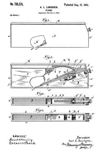
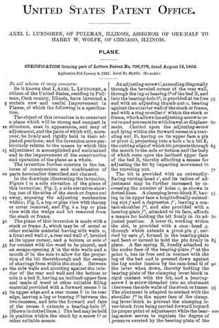
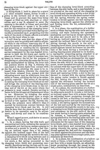
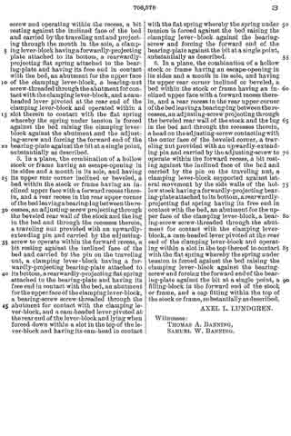
In the drawings illustrating the invention, Figure 1 is a side elevation of the plane of this invention; Fig. 2, a side elevation showing one of the sides of the stock or frame cut away, exposing the adjusting mechanism within; Fig. 3, a top or plan view with the cap or cover removed, and Fig. 4 a top or plan view with the wedge and bit removed from the stock or frame.
The plane of this invention is made with a stock: or frame A, which may be of metal or other suitable material having side walls a, a front end wall a’, a rear end wall a2, beveled at its upper corner, and a bottom or sole a3 for contact with the wood to be planed, and an escape-opening A’ in the side walls and a mouth a4 in the sole to allow for the projection of the bit therethrough and the escape of shavings from within the stock. Between the side walls and abutting against the interior of the rear end wall and the bottom or sole is a bed B, having an inclined upper face and made of wood or other suitable filling material provided with a forward recess b in its upper edge and a rear recess b’ in its rear edge, leaving a lug or bearing b2 between the two recesses, and into the forward end face of the recess b extends a bearing-hole b3, (Shown in dotted lines.) The bed may be held in position within the stock by a screw b4 or other suitable means.
An adjusting-screw C, extending diagonally through the beveled corner of the rear wall, through the lug or bearing b2 of the bed B, and into the bearing-hole b3, is provided at its free end with an adjusting thumb-nut c, bearing against the exterior wall of the stock or frame, and with a ring or collar c’ within the stock or frame, which allows the adjusting-screw to revolve and prevents its withdrawal or displacement. Carried upon the adjusting-screw and lying within the forward recess is a traveling nut D, having on its upper face a pin or pivot d, projecting into a hole e in a bit E, the cutting edge of which bit projects through the mouth in the sole or bottom and the body of which rests upon the inclined upper face of the bed B, thereby affording a means for adjusting the bit by imparting movement to the traveling nut.
The bit is provided with an outwardly-flaring cutting-head e’, and its radius of adjustment may be further increased by increasing the number of holes c, as shown in dotted lines. A clamping lever-block F, having in its upper face a longitudinally-extending slot f and a depression f’, leaving a contact-shoulder f2, and also provided with a bearing-plate f3, attached to its face, affords a means for holding the bit firmly in its adjusted position. A lever G, working within the slot, is provided with a cam-head g, through which extends a pivot-pin g’, carried by ears g2, formed in the bearing-plate and bent or turned to hold the pin firmly in place. A flat spring H, flxedly attached to the under face of the bearing-plate h3 at the point h, has its free end in contact with the lug of the bed and is pressed down against the lug under tension by the cam-head G of the lever when down, thereby holding the bearing-plate of the clamping lever-block in rigid contact with the bit, and a bearing-screw I is screw-threaded into an abutment i between the side walls of the stock or frame. The abutment is adapted to contact with the shoulder f2 in the upper face of the clamping lever-block to prevent the clamping lever-block from being carried forward beyond its proper point of adjustment while the bearing-screw serves to regulate the degree of pressure exerted by the bearing-plate of the clamping lever-block against the upper surface of the bit.
A filling-block J, held in place by a screw j or other suitable means, serves to add rigidity to the forward end of the stock or frame and to prevent the same from being clogged or filled up with shavings or other refuse, and a cap K, adapted to enter the opening in the stock or frame and provided with a depression or recess k in its under face for the reception of the clamping lever-block, and further provided with a flaring outwardly or extended top k’, projecting over the walls of the stock or frame, affords a suitable rest for the hand when in use.
It will thus be seen that the plane of this invention may be quickly and readily adjusted while in use without removing any of its parts by merely turning the adjusting-screw and projecting or receding the bit operated thereby. The clamping lever-block, with the spring compressed by the cam-headed lever, serves to hold the bit firmly and rigidly in place at all times; but when it becomes necessary to remove the bit for the purpose of sharpening or otherwise the same can be very easily accomplished by lifting the lever into the position shown in Fig. 3, whereby the cam-head is thrown back from contact with the flat spring, allowing the same to be released from tension, whereby the clamping lever-block released from contact with the adjusting-screw may be withdrawn from the stock or frame, allowing the bit to be subsequently removed. The action of the spring in raising the clamping lever-block at its rear end brings the contact of the bearing-plate of the clamping lever-block close to the cutting end of the bit at the point where the pressure is most needed, thereby serving to better hold the bit against displacement when in use. Moreover, by bringing the entire pressure of the bearing-plate upon a single portion of the bit the bearing-plate is made to bind or bite against the bit, thereby rendering the pressure more effective than if exerted by continuous contact between the clamping lever-block and the bit. It will thus be seen that the plane is simple and effective in its operation, easy in its adjustment, and strong and neat in its construction.
What I regard as new, and desire to secure by Letters Patent, is —
1. In a plane, having flat side walls and connecting end walls, inclosing the operative mechanism and having an escape-opening in its sides and a mouth in its sole, a bed having an inclined upper face, a bit resting against the inclined upper face of the bed and projecting through the mouthin the sole, a clamping lever-block lying between and in close contact with the side walls of the hollow stock, a flat spring connected to the clamping lever-block and projecting rearwardly therefrom having its free end in contact with the bed, an abutment for the upper face of the clamping lever-block extending between the side walls, and a cam-headed lever pivoted at the rear end of the clamping lever-block and operating within a slot in the top thereof to have its cam-head contact with the flat spring, whereby the spring under tension is forced against the bed raising the clamping lever-block against the abutment and forcing down the bit, substantially as described.
2. In a plane, the combination of a holder stock or frame having flat side walls and connecting end walls inclosing the operating mechanism and having an escape-opening in its sides and mouth and in its sole, a bed having an inclined upper face, a bit resting against the inclined face of the bed and projecting through the mouth in the sole, a clamping lever-block lying between and supported against lateral movement by the side wall of the stock having a forwardly-projecting bearing-plate attached to its bottom, a rearwardly-projecting spring attached to the bearing-plate, having its free end in contact with the bed, an abutment for the upper face of the clamping lever-block carried between the side walls of the stock, a bearing-screw, screw-threaded through the abutment for contact with the upper face of the clamping lever-block and a cam-headed lever pivoted at the rear end of the clamping lever-block and operating within a slot in the top thereof to contact with the spring whereby the spring under tension is forced against the bed, raising the clamping lever-block against the abutment forcing the forward end of the bearing-plate against the bit at a single point, substantially as described.
3. In a plane, the combination of a hollow stock or frame having an escape-opening in its sides and a mouth in its sole, a bed having an inclined upper face with a recess therein, an adjusting-screw projecting through the recess in the bed, a traveling nut carried by the adjusting-screw and operating within the recess, a bit resting against the inclined face of the bed and carried by the traveling nut, and projected through the mouth in the sole, a clamping lever-block supported against lateral movement by the side walls of the hollow stock having a bearing-plate attached to its bottom, a rearwardly-projecting flat spring attached to the bearing-plate and having its free end in contact with the bed an abutment for the upper face of the clamping lever-block, and a cam-headed lever pivoted to the lever-block and contacting with the spring whereby the spring under tension is forced against the bed and the clamping lever-block against the abutment and the bearing-plate against the bit at a single point, substantially as described.
4. In a plane, the combination of a hollow stock or frame, a bed having an inclined upper face with a recess therein, an adjusting-screw projecting through the recess in the bed, a traveling nut carried by the adjusting-screw and operating within the recess, a bit resting against the inclined face of the bed and carried by the traveling nut and projecting through the mouth in the sole, a clamping lever-block having a forwardly-projecting plate attached to its bottom, a rearwardly-projecting flat spring attached to the bearing-plate and having its free end in contact with the bed, an abutment for the upper face of the clamping lever-block, a bearing-nut screw-threaded through the abutment for contact with the clamping lever-block, and a cam-headed lever pivoted at the rear end of the clamping lever-block and operated within a slot therein to contact with the flat spring whereby the spring under tension is forced against the bed raising the clamping lever-block against the abutment and the adjusting-screw and forcing the forward end of the bearing-plate against the hit at a single point, substantially as described.
5. In a plane, the combination of a hollow stock or frame having an escape-opening in its sides and a mouth in its sole, and having its upper rear corner inclined or beveled, a bed within the stock or frame having an inclined upper face with a forward recess therein, and a rear recess in the rear upper corner of the bed leaving a bearing-lug between the recesses, an adjusting-screw projecting through the beveled rear wall of the stock and the lug in the bed and through the recesses therein, a traveling nut provided with an upwardly-extending pin and carried by the adjusting-screw to operate within the forward recess, a bit resting against the inclined face of the bed and carried by the pin on the traveling nut, a clamping lever-block having a forwardly-projecting bearing-plate attached to its bottom, a rearwardly-projecting flat spring attached to the bearing-plate and having its free end in contact with the bed, an abutment for the upper face of the clamping lever-block, a bearing-screw screw-threaded through the abutment for contact with the clamping lever-block, and a cam-headed lever pivoted at the rear end of the lever-block and lying when forced down within a slot in the top of the lever-block and having its cam-head in contact I with the flat spring whereby the spring under tension is forced against the bed raising the clamping lever-block against the bearing-screw and forcing the forward end of the bearing-plate against the bit at a single point, substantially as described.
6. In a plane, the combination of a hollow stock or frame having an escape-opening in its sides and a mouth in its sole, and having its upper rear corner inclined or beveled, a bed within the stock or frame having an inclined upper face with a forward recess therein, and a rear recess in the rear upper corner of the bed leaving a bearing-lug between the recesses, an adjusting-screw projecting through the beveled rear wall of the stock and the lug in the bed and through the recesses therein, a head on the adjusting-screw contacting with the outer face of the beveled corner, a traveling nut provided with an upwardly-extending pin and carried by the adjusting-screw to operate within the forward recess, a bit resting against the inclined face of the bed and carried by the pin on the traveling nut, a clamping lever-block supported against lateral movement by the side walls of the hollow stock having a forwardly-projecting bearing-plate attached to its bottom, a rearwardly-projecting flat spring having its free end in contact with the bed, an abutment for the upper face of the clamping lever-block, a bearing-screw screw-threaded through the abutment for contact with the clamping lever-block, a cam-headed lever pivoted at the rear end of the clamping lever-block and operating within a slot in the top thereof to contact with the flat spring whereby the spring under tension is forced against the bed raising the clamping lever-block against the bearing-screw and forcing the forward end of the bear-
ing-plate against the bit at a single point, a filling-block in the forward end of the stock or frame, and a cap fitting within the top of the stock or frame, substantially as described.
AXEL L. LUNDGREN.
Witnesses:
THOMAS A. BANNING,
SAMUEL W. BANNING.