
| PLEASE NOTE: The images presented on this page are of low resolution and, as a result, will not print out very well. If you wish to have higher resolution files then you may purchase them for only $2.95 per patent by using the "Buy Now" button below. All purchases are via PayPal. These files have all been cleaned up and digitally enhanced and are therefore suitable for printing, publication or framing. Each zip package contains all the images below (some packages may contain more), and purchased files can be downloaded immediately. |
UNITED STATES PATENT OFFICE.
_________________
JUSTUS A. TRAUT, OF NEW BRITAIN, CONNECTICUT.
PLANE.
_________________
SPECIFICATION forming part of Letters Patent No. 703,704, dated August 12, 1902.
Application filed May 20, 1901. Serial No. 60,992. (No model.)
_________________
To all whom it may concern:
Be it known that I, JUSTUS A. TRAUT, a citizen of the United States, residing in New Britain, in the county of Hartford and State of Connecticut, have invented certain new and useful Improvements in Planes, of which the following is a specification.
This invention relates to improvements in planes, and more particularly to that style of plane known as a “dado-plane,” and has for its object to provide adjustable means for limiting the depth to which the cutting of the plane may proceed.
A further object is to provide a plane of this character with a supplemental sole cooperative with the sole and which is easily and quickly adjustable and which can be securely maintained in its adjusted position.
A further object of my invention is to provide adjusting means which will also cooperate with the securing means for the purpose of maintaining the sole in its adjusted position.
In the drawings accompanying and forming part of this specincation is shown my invention applied to a form of dado-plane, which may be the preferred form, if desired.
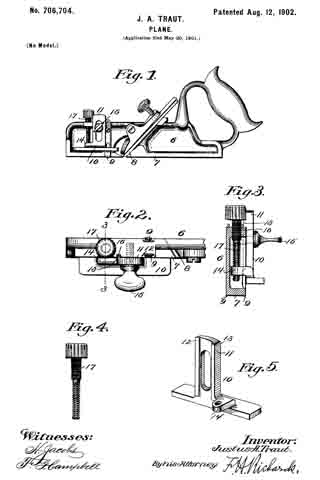
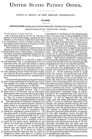
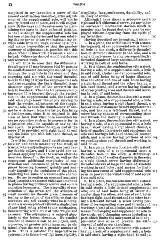
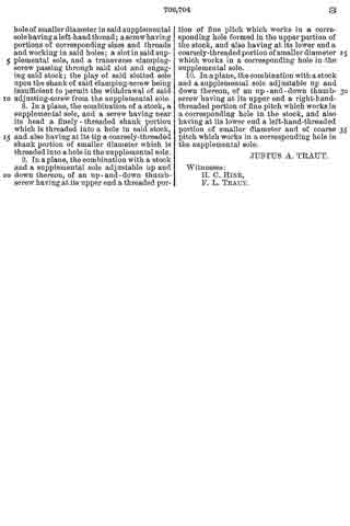
Figure 1 is an elevation of a plane having my invention applied thereto. Fig. 2 is a plan view of the forward end of the plane, showing the same on a somewhat larger scale. Fig. 3 is a cross-section on the line 3 3, Fig. 2. Fig. 4 is a form of adjusting-screw, and Fig. 5 is a form of supplemental sole or guide.
Like characters of reference designate the same parts in the various figures, wherein a plane-stock is represented generally by 6, having a sole 7, through which works a suitable plane-iron 8 and in connection with which are adjustable guide-knives 9 9. To the plane-stock is iitted a supplemental sole 10, having a projecting slotted arm 11, ways or guides 12 and 13, and a tapped boss 14. The supplemental sole is adapted to be secured to the plane-stock, generally at one side of the stock and forward of the mouth, by means of a set-screw 15 traversing the slotted arm and tapped hole in the plane-stock. The way 13 is shown as being of greater projection than the way 12, and it is adapted to enter and slide in a groove or guide 16 in the plane-stock; to prevent lateral movement or oscillation of the supplemental sole, the other way 12 being adapted to slide upon a face provided for it on the side wall of the plane-stock. The way 13 is shown in the drawings as having square corners and a fiat face, although any other or convenient form of way may be employed. The plane-stock is provided with a tapped boss located above the tapped boss in the supplemental sole. These bosses are adapted to be traversed by an adjusting-screw 17, preferably made with right and left threads of differential pitch. This screw is adapted for raising and lowering the supplemental sole, and it cooperates with the set-screw for maintaining the supplemental sole in its adjusted position.
It will be readily seen that by loosening the set-screw the supplemental sole may be raised and lowered at will by means of the screw 17. If the adjusting-screw is made with the portion traversing the boss in the stock of a greater number of threads to the inch than the part of the screw which traverses the boss in the supplemental sole, the head of the adjusting-screw will not have to be raised as great a distance as if both screw-threads were provided with the same number of threads, and hence I preferably employ such an embodiment herein. With such an organization increased range of adjustments of the supplemental sole may be affected by a very slight turn imparted to said screw. It will be observed that the said right and left hand differential adjusting-screw 17 is also of different diameters in its length, the portion thereof having the least number of threads being less in thickness or diameter than the portion having the greatest number of threads thereon, such construction permitting the insertion or passage of the said adjusting-screw through the tapped opening in the boss of the stock, it being evident that if the screw was of the same diameter throughout it could not be passed through such opening on account of its differential character and the right and left hand directions of its threads, the said tapped opening in the boss referred to being only adapted to receive that portion of the screw of the greatest diameter and greatest number of threads per inch ratio.
By the organization of the parts that is contemplated in my invention a screw of the general construction described, after adjustment of the supplemental sole, will not be readily jarred out of place, and it will cooperate with the ways and the set-screws for maintaining the parts in their adjusted position, so that although the supplemental sole has but one adjusting device and but one retaining device per se it has two maintaining devices aside from the ways, rendering all pivotal action impossible, so that the greatest accuracy of adjustment is possible with this plane, which in fine work it is essential should be had. Otherwise the tool would not do neat and accurate work.
It will thus be seen that the differential thumb-screw 17 may be assembled by passing its small-diameter coarsely-threaded tip end through the large hole in the stock and then engaging said tip with the small threaded hole in the lug 14 upon the supplemental sole and also engaging the finely-threaded large-diameter upper end of the screw with the hole in the stock. Then the transverse clamping-screw 15 is inserted through the vertical slot in the supplemental sole, the shank of said clamping-screw thereupon serving to limit the vertical adjustment of the supplemental sole, so that the thumb-screw 17 cannot be withdrawn from the latter, this being a desideratum, since it is required in this class of tools that when once assembled for use no operation such as is necessary for its adjustment shall be capable of taking the tool apart. In practice the upper end of the screw 17 is provided with right-hand thread and the lower end with left-hand thread, as illustrated.
It will be observed that I avoid slotting or forking, and hence weakening the stock, as is usual where adjusting-screws are used having double collars, and I also avoid the expense of applying a collar to a screw after the insertion thereof in the stock, as well as the consequent additional complexity of construction and looseness of parts, such small pieces becoming loosened quickly and seriously impairing the usefulness of the plane, rendering the same of a ramshackle character. By my invention an ease and accuracy of adjustment are secured which are not found in planes having ordinary screws and collars and other loose parts. The integrality of construction of the screw and the absence of small accessories thereto gives firmness of feeling to the action of the slide, so that the workman can tell exactly what he is doing. All this is accomplished without a single piece of any kind being added to the mechanism, thus securing a minimum of both weight and expense. The adjustment is reduced absolutely to the fewest elements. No smaller number of elements can be employed, and, moreover, no greater advantages can be obtained from the use of a greater number of parts. Thus is satisfied the imperative requirements in this art — of lightness, rigidity, simplicity, inexpensiveness, durability, and delicacy of action.
Although I have shown a set-screw and a right and left differential screw, yet any other or convenient mechanical devices which in practice may be found desirable may be employed without departing from the spirit of my invention.
Having described my invention, I claim —
1. In a plane, the combination with a stock having a sole, of a supplemental sole, a threaded hole in the stock, a differently-threaded hole of different diameter in the sole, and a single thumb-screw having correspondingly-threaded shanks of large and small diameters working in both of said holes.
2. In a plane, the combination with a stock having a sole, of a supplemental sole, a hole in said stock, a hole in said supplemental sole, one of said holes being of larger diameter than the other and one of said holes having a right-hand thread and the other having a left-hand thread, and a screw having shanks of corresponding sizes and threads and working in both of said holes.
3. In a plane, the combination with a stock having a sole, of a supplemental sole, a hole in said stock having a right-hand thread, a hole of smaller diameter in said supplemental sole, and having a left-hand thread, and a screw having shanks of corresponding sizes and threads and working in said holes.
4. In a plane, the combination with a stock having a sole, of a supplemental sole, a hole in said stock having a right-hand thread, a hole of smaller diameter in said supplemental sole and havinga left-hand thread of coarser pitch, and a screw having portions of corresponding sizes and threads and working in said holes.
5. In a plane, the combination with a stock having a sole, of a supplemental sole; a threaded hole in the stock; a differently-threaded hole of smaller diameter in the sole; a single thumb-screw having differently-threaded shanks of large and small diameters working in said holes; and means for limiting the movement of said supplemental sole so as to prevent the withdrawal of said screw from said sole.
6. In a plane, the combination with a stock having a sole, of a supplemental sole; a hole in said stock; a hole in said supplemental sole; one of said holes being of larger diameter than the other, and one of said holes having a right-hand thread and the other having a left-hand thread; a screw having portions of corresponding sizes and threads and working in both of said holes, and detachable means for clamping said supplemental sole to the stock; said clamping means including a part which limits the movement of said supplemental sole so as to prevent the withdrawal of said screw therefrom.
7. In a plane, the combination with a stock having a sole, of a supplemental sole; a hole in said stock having a right-hand thread 5 a hole of smaller diameter in said supplemental sole having a left-hand thread; a screw having portions of corresponding sizes and threads and working in said holes; a slot in said supplemental sole, and a transverse clamping-screw passing through said slot and engaging said stock; the play of said slotted sole upon the shank of said clamping-screw being insufficient to permit the withdrawal of said adjusting-screw from the supplemental sole.
8. In a plane, the combination of a stock, a supplemental sole, and a screw having near its head a finely-threaded shank portion which is threaded into a hole in said stock, and also having at its tip a coarsely-threaded shank portion of smaller diameter which is threaded into a hole in the supplemental sole.
9. In a plane, the combination with a stock and a supplemental sole adjustable up and down thereon, of an up-and-down thumb-screw having at its upper end a threaded portion of fine pitch which works in a corresponding hole formed in the upper portion of the stock, and also having at its lower end a coarsely-threaded portion of smaller diameter which works in a corresponding hole in the supplemental sole.
10. In a plane, the combination with a stock; and a supplemental sole adjustable up and down thereon, of an up-and-down thumb-screw having at its upper end a right-hand-threaded portion of line pitch which works in a corresponding hole in the stock, and also having at its lower end a left-hand-threaded portion of smaller diameter and of coarse pitch which works in a corresponding hole in the supplemental sole.
JUSTUS A. TRAUT.
Witnesses:
H. C. HINE,
F. L. TRAUT.