

| PLEASE NOTE: The images presented on this page are of low resolution and, as a result, will not print out very well. If you wish to have higher resolution files then you may purchase them for only $2.95 per patent by using the "Buy Now" button below. All purchases are via PayPal. These files have all been cleaned up and digitally enhanced and are therefore suitable for printing, publication or framing. Each zip package contains all the images below (some packages may contain more), and purchased files can be downloaded immediately. |
UNITED STATES PATENT OFFICE.
_________________
JUSTUS A. TRAUT, OF NEW BRITAIN, CONNECTICUT.
GROOVING-PLANE.
_________________
SPECIFICATION forming part of Letters Patent No. 707,281, dated August 19, 1902.
Application filed April 28, 1902. Serial No. 104,972. (No model.)
_________________
To all whom it may concern:
Be it known that I, JUSTUS A. TRAUT, a citizen of the United States, residing in New Britain, in the county of Hartford and State of Connecticut, have invented certain new and useful Improvements in Grooving-Planes, of which the following is a specification.
This invention relates to planes; and it consists substantially in the improvements hereinafter particularly described.
The invention has reference more especially to planes such as are employed for cutting or forming grooves in the surfaces of wood and other materials; and the principal object of the invention is to provide a plane of this character with means for effecting the cutting or formation in the surface of the work operated upon of grooves having sides or walls which are curved from end to end, and also to provide means for insuring the evenness of cut or formation of the angular edges of the grooves, as well as the bases and sides thereof.
A further object is to provide a grooving-plane of this special character with means for maintaining or preserving the true curviinear path of the cutting devices of the plane throughout the full extent of the grooves formed thereby, and also to provide means whereby the plane may be readily adapted to the cutting or formation of grooves having sides or walls of different or varying degrees of curvature.
A still further object of the invention is to provide a plane of this character which is exceedingly simple and easily handled in the performance of the work required of it, and also to provide means for meeting all requirements of use of the plane.
The above and additional objects are attained by means substantially such as are illustrated in the accompanying drawings, in which —
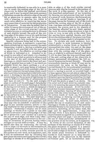
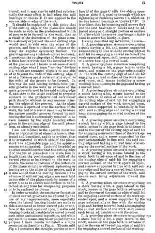
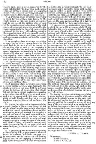
Figure 1 is a view in perspective of a grooving-plane structure embodying the essential features of my improvements, the said plane being shown as applied for use in the cutting or formation of curved grooves in the surface of a block of wood or other piece of work operated upon; and Fig. 2 is a bottom plan view of the plane structure, showing an element of my improvements which is omitted from Fig. 1 for the purpose of clearness. Fig. 3 is an enlarged bottom plan view in detail of the cutting devices to more clearly indicate the organization thereof for effecting their respective functions. Fig. 4 is a view in perspective of a part of the gage of the plane, showing a modification thereof for enabling the formation in the work operated upon of grooves having sides or walls of less than a predetermined curvature from end to end.
Before proceeding with a more detailed description it may be stated that while I have herein provided an ordinary grooving-plane with special means for the cutting of grooves having sides or walls which are curved from end to end it will be understood that the adaptability or capacity of the plane for cutting grooves having straight sides or walls from end to end is not altered in the slightest respect. Hence the greater advantage of my improvements. With some kinds of planes for cutting or forming straight-sided grooves in the work operated upon it is usual to employ a suitable gage having a straight edge or face for moving upon or against a corresponding straight edge or face formed on the adjacent part of the work, the said gage serving to guide the cutting devices evenly and being adjustable, by which to vary the distance of the grooves from the edges of the work as well as from each other.
In constructing a grooving-plane according to my present improvements I may employ a well-known form of plane having at one side thereof an adjustable gage formed with a straight edge extending substantially parallel with the sides of the plane-stock, and to said straight edge I apply one or more specially-constructed lateral bearings for the plane structure, said bearings being designed to work upon or against one side or edge of the work in the formation of grooves having either straight or curved sides or walls. For the cutting or formation of straight-sided grooves the adjacent side or edge of the work is made straight, while for the cutting or formation of grooves having curved sides the adjacent side or edge of the work operated upon is constructed in correspondence with the desired degree of curvature of the sides of the grooves to be formed, and it may be stated that the plane structure is equally operative whether the lateral bearings referred to are applied to a concave surface or to a convex surface. In either case the plane structure is constantly deflected to one side in a manner to cause the cutting edge of the bit or plane-iron to follow the desired curvilinear path, and it may be stated that such constant deflection causes the effective edge of the said bit or plane-iron to operate upon the work with a glancing or shearing cut, which is much more effective in removing the necessary quantities of material for the production of the grooves. It may also be stated that in order to insure the evenness of cut of the angular edges of the curved grooves I provide suitable scorers or cutting devices in advance of and slightly beyond the ends of the cutting edge of the plane-iron or bit, said devices operating in a manner and for the purpose hereinafter more fully understood.
Specific reference being had to the accompanying drawings, A represents a grooving-plane embodying my improvements, the same comprising a stock a, having a suitable grip or handle b and provided with the usual bit or plane-iron c, the effective or cutting edge of which is indicated at d. Attached or secured to one side of said stock a is a bracket B, which is provided at points in advance and to the rear of the said cutting edge d with bearings e e, which receive the inner end portions of parallel bars or rods f f, on which are slidably fitted the sleeve portions g g of a guide or gage C, said gage being of ordinary form and constructed with a straight edge or surface h adjacent the said plane-stock a, said sleeve portions being each provided with a set-screw i, working in the side thereof, the said screws being forthe purpose of tightening the gage in diiferent positions of adjustment on said bars or rods f f. To the said straight edge or surface of the said gage I detachably secure one or more lateral bearings or blocks D, having curved faces m, which are designed to bear upon a curved side or edge l of the work operated upon in the application of the plane structure to cut or form curved grooves in the surface of such work, substantially as is indicated at Fig. 1. The said bearings or blocks D may be constructed of wood, metal, or othersuitable material, as is apparent, and they may also be attached or secured to the gage in any suitable manner, screws o o being employed for that purpose in the present instance. Preferably I employ one of such bearings or blocks D at a point to one side of and in advance of the cutting edge d of the bit or plane-iron c and another at a point to the rear of such edge, and thus I may effectually operate the plane structure in the cutting or formation of grooves having either straight or curved sides or walls. It may be stated also that by continuing the curved side or edge l of the work in the formation of a complete circle the plane structure may be operated to cut or form circular grooves in the surface of such work, as is apparent, and it will be understood that by reversing the said plane structure and applying the curved bearings or blocks D to the opposite concave side or edge p of the work similar curved grooves may also be formed in the surface of the work in a like manner. In the use of this described embodiment of my invention for forming curved grooves from end to end of a piece of work, however, the foremost one of the said curved blocks or bearings D of the gage leaves the foremost end of the work before the cutting edge of the bit or plane-iron c has been carried forward far enough to complete the groove, and in the absence of the bearing afforded by said block against the work the entire plane structure is apt to twist or turn to one side or the other from the moving force applied thereto, and thus divert the cutting edge of the plane-iron from the true curvilinear path it is intended to follow. To obviate any such tendency, however, I prefer in most instances to employ substantially a similar block or bearing D2 intermediate the other two and at the same side of the plane-stock substantially coincident with the cutting edge d of the plane-iron, or slightly in advance thereof, and thus it will be seen that the true curvilinear path of the said cutting edge of the plane-iron is always maintained throughout the full extent of the grooves formed thereby. The said intermediate hearing or block D2 may not be constructed the same as the bearings or curved blocks D D; but preferably I construct the same in the present instance of a simple screw r, having a curved or rounded head S to bear against the curved side or edge of the work, said screw being adjustably inserted in a threaded opening therefor extending through the connecting member f2 between said blocks D D and the guide or gage C, as shown. On the outer end of said screw is a suitable jam-nut u for securing the same to the positions to which it may be adjusted. It will be understood that in some instances I may employ the said intermediate bearing D2 alone and dispense vrith the outer bearings or blocks D D for certain kinds of work — as, for instance, when cutting or forming curved grooves of exceedingly limited extent or dimensions from end to end. In most cases, however, I prefer the use or employment of said outer bearings or blocks on account of the stability afforded thereby in the operation of the plane structure, including, as the latter does, the gage and its appurtenances. I may also add that while I have herein illustrated my improvements as applied to a certain form of grooving plane and gage I am not limited to the use of these particular embodiments in the practice of my invention, as is apparent.
In virtue of the curved formation of the surfaces of the bearings or blocks D D when the plane structure is applied in a manner to have such blocks cobperate with the concaved side or edge of the work operated upon the whole plane structure is deflected inwardly in such manner as to keep the cutting edge of the plane-iron in the desired curvilinear path, all as hereinbefore mentioned, and it may also be said that substantially the same effect is had when the said bearings or blocks D D are applied to the convex side or edge of the work.
It should be explained at this point that if the cutting edge of the plane-iron should be made as wide as the predetermined width of groove to be formed in the work, then as a result of the deflection of the plane structure already explained the said cutting edge would tend to ride over the edges of the grooves, and thus mutilate said edges or destroy the angular symmetry thereof. To guard against any such destructive tendency, I construct the cutting edge of the plane-iron a little less in width than the intended width of the groove and I locate in advance of said cutting edge what I term “scoring” devices 2 2, which are arranged slightly to one side of or beyond the ends of the cutting edge d or at a distance apart substantially equal to the width of the groove to be formed. In this way the said scoring devices form parallel grooves in the work in advance of the main groove formed by the said cutting edge d, and thus is the latter enabled to properly conform to the predetermined curvilinear path therefor without in any manner injuring the edges of the grooves. As the plane structure is operated over the surface of the work, the bed of material remaining between the narrow parallel grooves formed by said scoring devices is successfully removed in an even manner by the slight shearing effect given to the cutting edge of the said plane-iron, as already mentioned.
I am not limited to the specific construction or organization of elements herein illustrated and described, and it is evident that it is immaterial at which side of the plane-stock the adjustable gage and its appurtenances are supported. It should be added as another reason therefor that the cutting edge d of the bit or plane-iron c is made less in length than the predetermined width of the curved groove to be formed in the work to enable the same to partake of the deflection of the plane structure without upturning or tearing away the edges of the groove, and it is also added that the scoring devices 2 2 in advance of said cutting edge d are each held to one side of the plane-stock by means of a screw 6, so as to enable said devices to be detached at any time for sharpening purposes or to be replaced by others.
In order to enable the cutting or formation of short curved grooves to be edected by the use of my improvements, more especially when the lateral bearing-blocks are made to ride a concaved or inner curved side or surface of the work operated upon, I make said bearing-blocks adjustable to be moved toward each other and secured in position, and while any suitable means may be employed for this purpose I have herein indicated a simple construction therefor at Fig. 4. Thus in said Fig. 4 I construct the straight portion or surface h2 of the gage C with two oblong openings or slots 8 8, passing through which are tightening or fastening screws 9 9, which enter the lateral bearings or blocks D3 D3. It is evident that by loosening said screws they and the said bearings or blocks may be adjusted along said straight portion or surface h2, after which the screws may be again tightened to secure the blocks in place.
Having described my invention, I claim —
1. A grooving-plane structure comprising a stock having a bit, and means supported substantially in line with the cutting edge of said bit for engaging a curved surface of the work operated upon, said means consisting of a screw having a curved head.
2. A grooving-plane structure comprising a stock having a bit, a gage lateral to the stock, and means on the gage substantially in line with the cutting edge of said bit for engaging a curved surface of the work operated upon, said means including a screw working in an opening in the gage and having a curved head.
3. A grooving-plane structure comprising a stock having a bit, means lateral to the stock both in advance of and to the rear of the cutting edge of said bit for engaging a curved surface of the work operated upon, and a screw supported substantially in line with said cutting edge and having a curved head also engaging the curved surface of the work.
4. A grooving-plane structure comprising a stock having a bit, a gage lateral to the stock, means on the gage both in advance of and to the rear of the cutting edge of said bit for engaging a curved surface of the work operated upon, and a screw supported by the gage substantially in line with the said cutting edge and having a curved head also engaging the curved surface of the work.
5. A grooving-plane structure comprising a stock having a bit, means lateral to the stock both in advance of and to the rear of the cutting edge of said bit for engaging a curved surface of the work operated upon, and a screw supported in line with said cutting edge and having a curved head also engaging the curved surface of the work, said means each being adjustable toward the other.
6. A grooving-plane structure comprising a stock having a bit, a gage lateral to the stock, means on the gage both in advance of and to the rear of the cutting edge of said bit for engaging a curved surface of the work operated upon, and a screw supported by the gage substantially in line with the cutting edge and having a curved head also engaging the curved surface of the work, said means each being adjustable toward the other.
7. A grooving-plane structure comprising a stock having a bit, a gage lateral to the stock, means on the gage both in advance of and to the rear of the cutting edge of said bit for engaging a curved surface of the work operated upon, and a screw supported by the gage substantially in line with said cutting edge and having a curved head also engaging the curved surface of the work, said gage being adjustable toward and from the stock.
8. A grooving-plane structure comprising a stock having a bit, a gage lateral to the stock, means on the gage both in advance of and to the rear of the cutting edge of said bit for engaging a curved surface of the work operated upon, and a screw supported by the gage substantially in line with said cutting edge and having a curved head also engaging the curved surface of the work, said gage being adjustable toward and from the stock, and said means each being adjustable toward the other.
9. A grooving-plane structure comprising a stock having a bit, means lateral to the stock both in advance of and to the rear of the cutting edge of said bit for engaging a curved surface of the work operated upon, a screw supported substantially in line with the cutting edge and having a curved head also engaging the curved surface of the work, and scoring devices located beyond the ends and in advance of the said cutting edge.
10. A grooving-plane structure comprising a stock having a bit, a gage lateral to the stock, means on the gage both in advance of and to the rear of the cutting edge of said bit for engaging a curved surface of the work operated upon, a screw supported by the gage substantially in line with the cutting edge and having a curved head also engaging the curved surface of the work, and scoring devices located beyond the ends and in advance of the said cutting edge.
11. A grooving-plane structure comprising a stock having a bit, a gage lateral to the stock, a block on the gage both in advance of and to the rear of the cutting edge of said bit and having acurved surface for engaging a curved surface of the work operated upon, and a screw supported by the gage intermediate of said blocks and having a curved head also engaging the curved surface of the work.
12. A grooving-plane structure comprising a stock having a bit, a gage lateral to the stock, a block on the gage both in advance of and to the rear of the cutting edge of said bit and having a curved surface for engaging a curved surface of the work operated upon, and a screw supported by the gage intermediate of said blocks and having a curved head also engaging the curved surface of the work, said blocks being adjustable toward each other longitudinally of the gage, and said screw being adjustable toward and from the stock.
13. A grooving-plane structure comprising a stock having a bit, a gage parallel with and lateral to the stock, means on the gage both in advance of and to the rear of the cutting edge of said bit for engaging a curved surface of the work operated upon and adapted to deflect the structure laterally in the planing movements thereof to cause said cutting edge to follow a path parallel with such curved surface, and similar means substantially in line with said cutting edge, said gage being adjustable toward and from the stock, and each of the means specified being adjustable on the gage and consisting of a lateral bearing or block having a curved surface.
14. A grooving-plane structure comprising a stock having a bit, a gage parallel with and lateral to the stock, means on the gage both in advance of and to the rear of the cutting edge of said bit for engaging a curved surface of the work operated upon and adapted to deflect the structure laterally in the planing movements thereof to cause said cutting edge to follow a path parallel with such curved surface, and a screw supported by the gage substantially in line with said cutting edge and having a curved head also for engaging the curved surface of the work, said gage being adjustable toward and away from the stock, and said means each being adjustable on the gage and consisting of a lateral bearing or block having a curved surface.
15. A grooving-plane structure comprising a stock having a bit, a gage parallel with and lateral to the stock, means on the gage both in advance of and to the rear of the cutting edge of said bit for engaging a curved surface of the work operated upon and adapted to deflect the structure laterally in the planing movements thereof to cause said cutting edge to follow a path parallel with such curved surface, sirnilar means substantially in line with said cutting edge, and scoring devices located beyond the ends and in advance of the cutting edge, said gage being adjustable toward and from the stock, and each of the means specified being adjustable on the gage and consisting of a lateral bearing having a curved surface.
16. A grooving-plane structure comprising a stock having a bit, a gage parallel with and lateral to the stock, means on the gage both in advance of and to the rear of the cutting edge of said bit for engaging a curved surface of the work operated upon and adapted to deflect the structure laterally in the planing movements thereof to cause said cutting edge to follow a path parallel with such curved surface, a screw supported by the gage substantially in line with said cutting edge and having a curved head also for engaging the curved surface of the work, and scoring devices located beyond the ends and in advance of the cutting edge, said gage being adjustable toward and from the stock, and said means each being adjustable on the gage and consisting of a lateral bearing or block having a curved surface.
JUSTUS A. TRAUT.
Witnesses:
EBEN STRONG,
FRANK S. TRAUT.