
| PLEASE NOTE: The images presented on this page are of low resolution and, as a result, will not print out very well. If you wish to have higher resolution files then you may purchase them for only $2.95 per patent by using the "Buy Now" button below. All purchases are via PayPal. These files have all been cleaned up and digitally enhanced and are therefore suitable for printing, publication or framing. Each zip package contains all the images below (some packages may contain more), and purchased files can be downloaded immediately. |


UNITED STATES PATENT OFFICE.
_________________
ALIX W. STANLEY, OF NEW BRITAIN, CONNECTICUT, ASSIGNOR TO THE STANLEY RULE
& LEVEL COMPANY, OF NEW BRITAIN, CONNECTICUT, A CORPORATION OF CONNECTICUT.
PLANE.
_________________
SPECIFICATION forming part of Letters Patent No. 707,365, dated August 19, 1902.
Application filed March 5, 1902. Serial No. 96,773. (No model.)
_________________
To all whom it may concern:
Be it known that I, ALIX W. STANLEY, a citizen of the United States, residing at New Britain, in the county of Hartford, State of Connecticut, have invented certain new and useful Improvements in Planes, of which the following is a full, clear, and exact description.
This invention relates to planes.
The object of this invention is to provide a construction by which the support for the cutting-iron shall be such that the chattering of said iron in use is entirely prevented. In planes of this character the support for the cutting tool or iron is termed a “frog,” and the frog is commonly made in a piece separate from the body or stock of the plane. The reasons for this are several, among which is that an adjustability is permitted whereby the effective size of the opening or throat in the stock or base of the plane through which the cutting-iron works may be narrowed or widened, as desired, according to the character of the work. Another is that the frogs are provided with the adjusting device, and it is more convenient to equip said frogs with said adjusting devices when they are separate from the stocks than would be the case if they were integral with the same.
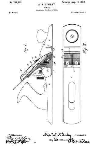
The accompanying drawings show the preferred form of the invention.
In said drawings, Figure 1 is a side elevation, partly in section, of a plane embodying my invention. Fig. 2 is a plan view of the base or stock portion of the plane with the frog, cutting-iron, and the associated parts removed. Fig. 3 is a similar view of a modification. Fig. 4 is a perspective view of a frog such as is adapted for use in connection with the stock shown in Figs. 1 and 2. Fig. 5 is a perspective view of a modified form of frog adapted for use in connection with the stock or frame shown in Fig. 3.
In the particular form shown, 1 is the floor or sole of the stock portion.
2 2 are side walls or flanges.
3 is a throat or slot in the bottom or floor 1 of the stock.
4 is a frog which is supported, preferably, on two seats or bearings. These seats may comprise an elevated chair 5 and a bearing 6 upon the floor 1. The bearing 6 is formed by thinning down the floor 1 directly to the rear of the throat 3. This thinning down may be effected in casting the stock, (for it is by the casting process that stocks are ordinarily made,) or it may be formed by machine-work after the casting is produced. The purpose of making the bearing 6 thin will hereinafter be explained.
7 7 are screw-passages in the frog, preferably elongated so as to permit the frog to be adjusted forward or back, thereby changing the position of the cutting edge of the plane-iron in the throat 3.
8 8 are clamp-screws (two are preferably used) by which the frog 4 is secured to the stock. The clamp-screws 8 are located between the elevated bearing 5 and the bearing 6 for the frog, so that when the screws are set down they will firmly clamp said frog against both of said bearings 5 and 6. In consequence of the fact that these bearings are spaced apart considerably when the parts are assembled it is impossible for the frog to chatter upon the stock. By loosening the screws 8 the frog may be moved backward or forward, as desired, to place the cutting edge of the plane-iron correctly relatively to the throat 3.
9 is the plane-iron, the lower edge of which is sharpened in the usual manner and is caused to project through the throat as desired. It is preferred that separate adjusting devices be provided to facilitate the longitudinal positioning of the plane-iron.
10 is a cap of the ordinary form carrying the cam 11, also of the ordinary form, and 12 is a cap-screw carried by the frog 4., which projects through a slot in the plane-iron 9 and engages the cap 10 in the usual manner, so that when the parts are assembled the plane-iron is clamped in proper position.
Manifestly the method of clamping the plane-iron to the frog may be varied as desired, since the particular device for accomplishing this end constitutes no part of this invention, excepting as it is obvious that the clamping means should take a long bearing upon the plane-iron to hold it in proper engagement throughout substantially the full bearing-surface of the frog 4.
Inasmuch as the frog is independent of the stock and inasmuch as the clamping effect of the screw 8 is considerable and inasmuch as the bottom 1 directly to the rear of the throat 3 is thin, the clamping effect of the screw 8 might tend to slightly bulge the said thin portion of the door, since this portion preferably affords one of the bearings for the frog. In order to prevent this bulging, I provide a supporting and stiffening rib 13, which in its preferred form is cast integral with the stock of the plane and preferably so as to extend from said thin portion to a heavier portion of the stock. Any desired number of these strengthening-ribs maybe provided. In Fig. 2 one of these ribs 13 is shown. In Fig. 3 two ribs 13 13 are provided; otherwise the construction is identical. I mention this, because it is obvious that the number of stiffening-ribs employed is immaterial. In order to permit the frog to take a proper bearing, I channel out the under side of the frog directly above the strengthening-ribs 13, so that the frog will not encounter the rib when the parts are assembled, but will take its proper bearing upon the seat 6. Manifestly this construction may be modified in a variety of ways.
In operation it is obvious that unless an efficient bearing is provided for the member or members which support the cutting-iron the passing of the plane over the material to be smoothed or cut might cause a vibration and a chattering of the parts. It is therefore desirable to have the forward bearing or point of contact which the plane-iron takes with the stock or parts associate therewith as close to the cutting edge as possible. Heretofore no special attention has been paid to thinning the metal of the stock directly to the rear of the throat. By thinning the metal at this point as I have done the frog supports the plane-iron almost down to its lower edge. In fact, when the best effect is produced the only unsupported portion is the beveled portion formed in shaping the edge. This will be seen in the section Fig. I. While this is of advantage generally, it is of particular advantage in that type of planes wherein the frog is adjustable longitudinally of the plane, so as to widen or narrow the throat, or rather that portion of the throat forward of the cutting edge of the plane-iron. By this invention in its preferred form a greater range of adjustability is rendered possible, since the frog may be moved to the rear of the throat to a considerable extent before the knife or cutting-iron will touch the metal of the stock. This is due to the fact that the metal of the stock may be made so thin at this point that the cutting-iron will not engage it, excepting at a point very close to its cutting edge. As a direct consequence the plane-iron may be adjusted forward or backward substantially the full width of the throat and still have an unimpaired and effective bearing directly upon the frog.
While I have shown and described a preferred form for the door of the stock to the rear of the throat, it is obvious that this may be modified in a variety of ways without departing from the spirit and scope of my invention, which in this respect relates to the provision of a suitable strengthening means adapted to reinforce the door immediately to the rear of the throat, so that that portion may be made thin, while the portion farther to the rear is of sufficient thickness to be self-supporting.
What I claim is —
1. In a plane, the combination with the stock, a frog, a plurality of bearings on said stock for said frog, and a clamping device located between said bearings, a slot or throat in the bottom or door of said stock portion, the bottom or door of said stock portion to the rear of said throat being thinned out up to the edge thereof, and means for strengthening said thinned-out floor.
2. In a plane, the combination with a stock having a plurality of seats for a detachable frog of a throat extending transversely of the stock and in the bottom thereof, the door of said stock directly to the rear of said throat being of thin metal, and strengthening-ribs extending from the heavy part of said stock to said thinned-out portion, substantially as described.
3. A stock for a plane having a transverse slot therein forming a throat for the passage of the plane-iron, the door to the rear of said throat being thin, the stock to the rear of said thin portion of the door being heavy, and a rib extending from said heavy portion to said thin portion, and strengthening and supporting the latter.
4. In a plane, a stock, a transverse slot therein forming a throat for the passage of the plane-iron, the door to the rear of said throat being thin, the stock to the rear of said thin portion of the door being heavy, and a plurality of ribs extending from said heavy portion to said thin portion, and strengthening and supporting the latter.
5. A plane having a stock portion provided with a throat, a frog, said stock portion being provided with two bearings for said frog, a rib connecting said two bearings, said frog being correspondingly grooved.
6. A plane having a stock portion provided with a throat, a frog, said stock portion being provided with an upper and a lower bearing for said frog, a rib connecting said two bearings, said frog being correspondingly grooved.
7. A plane having a stock portion provided with a throat, a frog, said stock portion being provided with an upper and a lower bearing for said frog, a screw having a seat between said bearings for securing said frog to said stock, a rib connecting said two bearings, said frog being correspondingly grooved.
Signed at New York, N. Y., this 15th day of February, 1902.
ALIX W. STANLEY.
Witnesses:
ROBT. S. ALLYN,
L. VREELAND.