| PLEASE NOTE: The images presented on this page are of low resolution and, as a result, will not print out very well. If you wish to have higher resolution files then you may purchase them for only $2.95 per patent by using the "Buy Now" button below. All purchases are via PayPal. These files have all been cleaned up and digitally enhanced and are therefore suitable for printing, publication or framing. Each zip package contains all the images below (some packages may contain more), and purchased files can be downloaded immediately. |
UNITED STATES PATENT OFFICE.
_________________
JUSTUS A. TRAUT AND HENRY S. WALTER, OF NEW BRITAIN, CONNECTICUT, ASSIGNORS TO
STANLEY RULE AND LEVEL COMPANY, OF NEW BRITAIN, CONNECTICUT, A CORPORATION OF CONNECTICUT.
PLANE-IRON CAP.
_________________
SPECIFICATION forming part of Letters Patent No. 707,368, dated August 19, 1902.
Application filed April 26, 1902. Serial No. 104,811. (No model.)
_________________
To all whom it may concern:
Be it known that we, JUSTUS A. TRAUT and HENRY S. WALTER, citizens of the United States, residing at New Britain, in the county of Hartford, State of Connecticut, have invented certain new and useful Improvements in Plane-Iron Caps, of which the following is a full, clear, and exact description.
Our invention relates to improvements in planes, and particularly to plane-iron caps.
It consists, mainly, in the improvement of what is termed the “cap-iron” or “cap-piece” in that class of planes in which the plane-iron is clamped to a frog by means of a screw or cam. By this invention we are able to construct a plane-iron cap much cheaper than heretofore and more efficient and durable, as well as more adaptable to the uses to which it may be put.
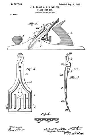
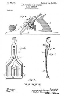
In the drawings, Figure l is a side elevation of a plane embodying our invention. Fig. 2 is a plan view of that part of the plane to which our invention relates. Fig. 3 is a longitudinal section on the center line of Fig. 2. Fig. 4 is a cross-section on the line X X of Fig. 2 looking in the direction of the arrows.
1 is a plane-stock.
2 is a plane-iron.
3 is a forward handle.
4 is a rear handle.
5 is what is commonly termed a “cap-screw, secured to a frog or support 6 for the plane-iron. The cap-iron 9 is so shaped and constructed as to be engaged at an intermediate point by the head of the screw 5 and at each end to bear upon the plane-iron or a plate, such as commonly associated therewith. In the drawings, Fig. 1, the cap is shown as engaging the forward or lower edge of the plane-iron and engaging the upper portion by means of a cam-pressed spring 7, 8 being the cam employed for clamping the parts. Thus far described the construction and operation of the parts are well known, and hence need not be described in detail.
In practice it is essential that the cap-iron shall be very strong and desirable that it be light in weight, and to that end I construct it, preferably, of wrought or sheet metal. The cap-iron includes a broad blade-like portion 91 and a narrower shank 10. The lower edge of the portion 91 engages with the plane-iron or a part thereof near the cutting edge, while the cam 8 is carried on the shank portion 10. The cap then is subjected to strains in a manner similar to a beam supported at the ends and loaded in the middle. For this reason in order to provide sufficient strength the edges of the shank 10 and a portion of the broader part 9 of the plane-iron are bent down at an angle to provide side bars or flanges 101 integral with the body portion of the plane-iron, and hence contributing to the plane-iron great rigidity and strength. Furthermore, the flanges provide a recess in which to receive the pivot-bearing 81 for the cam 8. In addition to this feature of construction, which contributes substantially to the strength of the cap-iron, we provide a corrugation 11, which preferably commences in the shank portion 10 of the cap-iron and extends downwardly toward the broader portion on opposite lines. In addition to these corrugations shorter corrugations 12 12 may be provided in the broader portion of the cap-iron, contributing vastly to the rigidity and strength of the device, which is preferably curved, as shown best in the side views numbered 1 and 3. The particular construction preserves the curved outline of the cap-iron and permits the employment of comparatively light wrought or sheet metal. The flanges 101 form a pocket in which to receive one end of the spring 7, which is preferably fixedly secured to the cap-iron, as well as a pocket for the bearing end of the cam 8 adjacent to the pivot or pin 81, upon which said cam turns. All of the ribs or corrugations extend generally in a longitudinal direction relatively to the cap-piece, and consequently give greater rigidity to it in a lengthwise direction than transversely.
It is advantageous to have the greater strength extend in longitudinal lines. Should the gage of the metal employed in shaping the cap-piece be so light as to permit any flexibility, it would be in a transverse direction at the lower edge only, and hence advantageous in permitting the lower edge of said cap-piece to yield and bear uniformly against the plane-iron or the plane-iron plate, which is usually employed therewith in planes of the class to which our invention is particularly applicable. In Fig. 4 it will be seen that the ribs are preferably hollowed on the under side, the said view showing the under side of said cap-piece uppermost.
What we claim, and desire to secure by Letters Patent, is —
1. In a plane, a cap-iron having flanges on opposite sides at its upper end, and ribs extending longitudinally of said iron.
2. A plane-iron cap for a plane having corrugations or ribs extending longitudinally thereof, substantially as described.
3. A plane-iron cap for a plane having corrugations or ribs 12 and 12 in the body and extending longitudinally thereof, as described.
4. A plane-iron cap for a plane having corrugations or ribs 11 extending up the shank and 12, 12 in the body extending longitudinally thereof, substantially as described.
Signed at New Britain, Connecticut, this 24th day of April, 1902.
JUSTUS A. TRAUT.
HENRY S. WALTER.
Witnesses:
W. J. WORUM,
EVERETT G. HOFFMAN.


