
| PLEASE NOTE: The images presented on this page are of low resolution and, as a result, will not print out very well. If you wish to have higher resolution files then you may purchase them for only $2.95 per patent by using the "Buy Now" button below. All purchases are via PayPal. These files have all been cleaned up and digitally enhanced and are therefore suitable for printing, publication or framing. Each zip package contains all the images below (some packages may contain more), and purchased files can be downloaded immediately. |
UNITED STATES PATENT OFFICE.
_________________
LUCAS C. CLARK, OF SOUTHINGTON, CONNECTICUT.
PLANE.
_________________
SPECIFICATION forming part of Letters Patent No. 708,318, dated September 2, 1902.
Application filed July 11, 1901. Serial No. 67,867. (No model.)
_________________
To all whom it may concern:
Be it known that I, LUCAS C. CLARK, a citizen of the United States of America, residing at Southington, in the county of Hartford and State of Connecticut, have invented a certain new and useful Improvement Applicable to Planes, of which the following is a description, reference being had to the accompanying drawings, wherein —
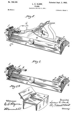
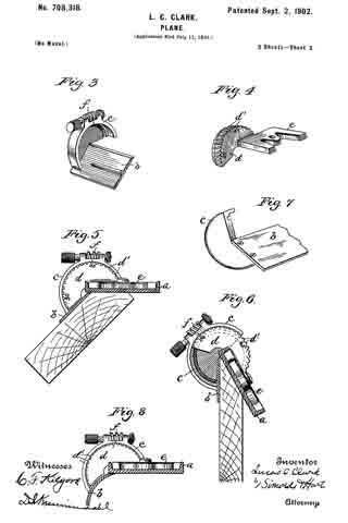
Figure 1 is a perspective view of a complete tool embodying said improvement. Fig. 2 is a perspective view of an adjustable leaf and appurtenances by which it may be attached to a common style of plane. Fig. 2a is a view of a portion of the plane-face and of the adjustable leaf with a portion of the latter broken away. Fig. 3 is a perspective view of one end of the adjustable leaf and appurtenances carried thereby. Fig. 4 is a perspective view of the disk-section peripherally worm-toothed and the attached plate adapted to be screwed, bolted, or otherwise fastened to a common plane. Fig. 5 is a cross-sectional view on the plane x x looking in the direction indicated by the arrow with the adjustable leaf and the plane-face adjusted at an angle of forty-five degrees each to the other. Fig. 6 is a view similar to Fig. 5 with the adjustable leaf and plane-face adjusted at an angle of thirty degrees each to the other. Fig. 7 is a perspective view of an end of the adjustable leaf attached to the rim-sector. Fig. 8 is a view similar to Fig. 5, showing the adjustable leaf in a curved form.
The object of the improvement is the production of a plane having a pivotally-attached adjustable leaf which within reasonable limits can be adjusted at any desired angle to the plane-face, the adjustable leaf acting in use as a guide for the plane for a variety of purposes.
In the accompanying drawings the letter a denotes the plane as a whole, and a’ denotes the cutter of the plane.
b denotes an adjustable leaf pivotally attached to the plane.
c denotes what may be termed “rim-sectors” made fast to the adjustable leaf in any suitable manner.
d denotes disk-sections lying within the rim part of the rim-sectors.
e denotes plates fast to the disk-sections and adapted to be screwed, bolted, or otherwise properly secured to the plane.
f denotes an operating-worm carried by a rim -sector, and d’ denotes worm-teeth on the periphery of a disk-section cooperating with said worm. It will readily be understood that by rotating the worm the adjustable leaf can be rotarily adjusted. The rim-sector carries on one edge one or more graduations, and the face of the disk-section carries corresponding graduations or figures, preferably the latter. Preferably one edge of the adjustable leaf is always overhung by the plane-face, and also, preferably, that same edge of the plane-face is always substantially in contact with the plane-face. These words “substantially in contact” do not mean actual contact, but something very closely akin to it, as near akin to it as is practicable for ordinary uses. It is also preferable that the said edge of the adjustable leaf be always overhung by the edge of the cutter of the plane. The adjustable leaf has by preference a flat face, but is susceptible of faces of other forms — as, for instance, the curved face shown in Fig. 8.
It will be readily understood that the worm might be attached to the disk-section and cooperate with worm-teeth on the rim-sector. The letters g and h denote parts of a screw-clamp for holding the adjustable leaf firmly in any position in which it may be set.
I claim as my improvement —
1. In combination, the plane, the adjustable leaf, the rim-sectors attached to the leaf, and the disk-sections within the rims of the rim-sectors, and attached mediately to the plane, all substantially as described and for the purposes set forth.
2. In combination, the plane, the adjustable leaf, the rim-sectors attached to the leaf, the disk-sections within the rims of the rim-sectors, and the planes attached to the disk-sections and adapted for attachment to and detachment from the plane, all substantially as described and for the purposes set forth.
3. In combination, the plane, the adjustable leaf, a rim-sector attached to the leaf, the worm borne by the rim-sector and the disk-section attached to the plane and peripherally worm-toothed, all substantially as described and for the purposes set forth.
LUCAS C. CLARK.
Witnesses:
D. I. KEIMENDAHL,
H. E. HART.