
| PLEASE NOTE: The images presented on this page are of low resolution and, as a result, will not print out very well. If you wish to have higher resolution files then you may purchase them for only $2.95 per patent by using the "Buy Now" button below. All purchases are via PayPal. These files have all been cleaned up and digitally enhanced and are therefore suitable for printing, publication or framing. Each zip package contains all the images below (some packages may contain more), and purchased files can be downloaded immediately. |

UNITED STATES PATENT OFFICE.
_________________
CHARLES H. FOX, OF NEW BRITAIN, CONNECTICUT, ASSIGNOR TO
THE STANLEY RULE & LEVEL COMPANY, OF NEW BRITAIN, CONNECTICUT,
A CORPORATION OF CONNECTICUT.
PLANE.
_________________
SPECIFICATION forming part of Letters Patent No. 710,678, dated October 7, 1902.
Application filed December 31, 1901. Serial No. 87,942. (No model.)
_________________
To all whom it may concern:
Be it known that I, CHARLES H. FOX, a citizen of the United States, residing in New Britain, in the county of Hartford and State of Connecticut, have invented certain new and useful Improvements in Planes, of which the following is a specification.
This invention relates to bench-planes; and it consists, substantially, in the improvements hereinafter more particularly described.
Without attempting to enumerate the advantages of the present invention by comparison with other planes hitherto devised it may be stated that the present invention has for its object to provide a plane of simple and effective construction and organization and one in which the plane mechanism is economically and compactly seated in place upon the stock in such manner as to overcome or prevent any tendency to chattering ot the operative portion of the plane-iron, and also to provide an extended bearing for the rear or under side of the supporting-frame of the plane mechanism, and to greatly strengthen the fastening for such frame without materially adding to the weight of the plane.
A further object is to provide means for preventing dislodgment or disorganization of the plane mechanism either in part or in entirety due to any tendency thereof to rise from its seat upon the stock, from drag upon the plane-iron, or from other causes.
A still further object of the invention is to provide means for fastening the supporting-frame to the stock in the most. rigid and secure manner, while readily permitting vertical or up and down adjustments of such frame for the purpose of effecting changes in the position of a wearing-sole in conformity with the needs thereof, and also to provide means whereby the up and down adjusting devices for the plane-iron are housed in part and protected against accidental displacement in the use of the plane.
The above and additional objects are attained by means substantially such as are illustrated in the accompanying drawings, wherein —
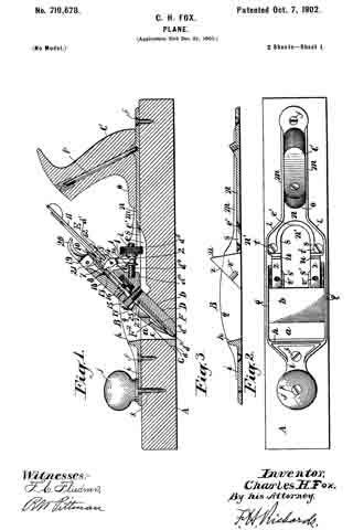
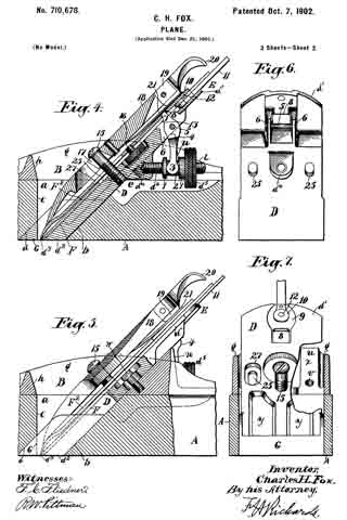
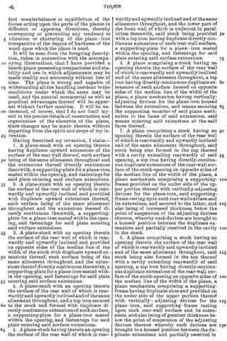
Figure 1 is a longitudinal sectional elevation of a plane embodying my improvements, said view being taken just to one side of the median line of the width of the stock, several of the parts being shown in elevation. Fig. 2 is a top or plan view thereof with the plane mechanism removed. Fig. 3 is a central longitudinal sectional view of the top iron of the plane. Fig. 4 is an enlarged view similar to Fig. 1 to more clearly indicate the construction and organization of parts or elements comprising or constituting the plane mechanism, the stock or body of the plane being broken off at each end. Fig. 5 is also a similar view taken to one side of the median line of the width of the stock and just to the outer side of one of the fastening-screws for the frame of the plane mechanism, so as to clearly show the construction and organization. Fig. 6 is a view looking at the rear or under side of the supporting-frame for the plane mechanism, said plate being minus any of such mechanism as well as the adjusting elements for the plane-iron; and Fig. 7 is a view looking at the front or upper side of the supporting-frame, the stock and top iron being shown in vertical section and the laterally-adjusting lever for the plane-iron being partly broken off.
Before proceeding with a more detailed description it may be stated that in the practice of my invention I provide the body or stock of the plane of any suitable wood, and I form therein from top to bottom an opening the surface of the rear wall of which is inclined to provide a seat of proper angle or inclination for the plane-iron mechanism and the surface of the front wall of which is specially constructed at the bottom of the stock to cooperate with the lower end of the frame of the plane mechanism, as and for the purpose hereinafter specifically explained. To provide an extended and continuous bearing-surface for the supporting-frame of the plane mechanism, I extend the rearwardly and upwardly inclined surface of the rear wall of the opening in the stock some distance above the top of the stock, and preferably such extension is in duplicate with the parts thereof on opposite sides of the median line of the width of the stock. The supporting-frame is provided separately with some suitable laterally and vertically adjusting devices for the plane-iron, and the said plane-stock and supporting-frame are so constructed that the principal parts of the said vertically-adjusting devices are snugly and conveniently housed in such manner as not to become broken or disarranged accidentally while the plane is in use, yet readily accessible for adjusting or changing the position of the plane-iron. Preferably the upward extensions of the surface of the rear wall of the opening in the stock are of metal, constituting integral parts of the plane-iron, and the supporting-frame of the plane mechanism is provided with a sole or wear plate receiving the wear of the plane and havinga throat for the play of the operative end of the plane-iron. The supporting-frame is also otherwise specially constructed at its lower end to cooperate with the said specially-constructed part of the surface of the front wall of the plane-opening to prevent uprising or dislodgment of said frame and the other parts of the plane mechanism supported or carried thereby, and preferably, also, the fastenings for the frame are introduced into the said duplicate metal extensions of the rear surface of the opening of the stock rather than in the stock itself. The construction enables use to be made of plane stocks or bodies of comparatively limited height and is otherwise especially advantageous, both from a commercial and practical point of view.
Specific reference being had to the accompanying drawings, wherein an embodiment of my invention is shown and which maybe the preferred embodiment, A represents the stock or body of the plane, constructed of any suitable wood for the purpose and formed therein at the proper point of its length with an opening a, the surface b of the rear wall of which is rearwardly and upwardly inclined at an angle of about forty-five degrees (45°) to the base of the plane, so as to give to the plane mechanism seated upon such surface the proper inclination within such opening. The lower corner of the front wall c of said opening a is also cut off or beveled to produce a similarly-inclined shorter surface d, which is preferably parallel with the said surface b, for the purpose hereinafter understood. In the top surface thereof the said plane stock or body is cut out or recessed a short distance centrally thereof, so as to provide a cavity e, leading rearwardly from the opening a and designed to partially receive the operating element of the up and down adjusting devices for the plane-iron in the manner shown and as hereinafter specifically set forth. Secured in place upon the upper portion of the stock or body by means of screws or similar fastenings f is the top iron B, which is constructed with parallel and slightly raised or elevated side portions g g, the inner surfaces of which may be practically flush or even with the corresponding surfaces of the sides of the opening a, already referred to. Said side portions g g are united by an integral rib h, connecting the same at about the upper forward edge of said opening a, and forwardly of said rib the said top iron is formed with a short longitudinal extension i, on which is seated the knob or forward handle j of the plane, said knob being held in place by a screw k, entering the stock through a suitable opening therefor in said forward extension. The rearward ends of the side portions g g of the top iron gradually decrease in height and slightly converge at l l, whence they terminate in parallel elevated flanges m m, formed on a rearward longitudinal extension n, and upon which latter, between said flanges, is seated the base o of the main or rear handle C of the plane, said handle being securely fastened in place by a screw-rod p, passing through the same and secured at its lower end in a threaded opening in the said extension n therefor. The forward part of said rearward extension it of the top iron is cut out or notched at n’, so as to bring the inner edges e’ thereof about even with the side and rearward edges of the recess or cavity e of the plane-stock, and thus are formed the integral flanges s s of the top iron, which are seated upon the upper surface of said stock on opposite sides of the said recess or cavity therein. Said flanges are each provided with a hole or opening for the passage of a screw t, which enters the stock on opposite sides of the median line of the width of the same, and thus is an extremely rigid and compact structure derived. Said side flanges s s of the top iron are each widened somewhat at s’, and they also constitute bases for preferably duplicate integral supports u u for the frame D of the plane mechanism E, said supports of course being also on opposite sides of the median line of the width of the plane and being integral at the outer sides thereof with the adjacent inner surfaces of the rear ends of the side portions g g of the top iron. In this way increased width or thickness of each of the said supports it is obtained for the formation therein of a threaded opening v for the reception of a screw w for securing the supporting-frame D in place and which construction does not materially add to the weight of the plane. The forward edges or faces x x of said supports u u are faced off in the same plane and at an upward and rearward inclination corresponding to the angle of inclination of the surface b of the rear wall of opening a in the stock, and thus said faces of the said supports constitute practical upward continuations or extensions of said surface b. In this way an increased, even, and continuous bearing-surface is obtained for the under side of the supporting-frame D of the plane mechanism, as is obvious. The frame D is substantially a rectangular plate the upper part d’ of which is comparatively thin, while the remaining lower portion thereof is of increased thickness, for the purpose hereinafter understood, although recessed or hollowed out, as at y y, on its upper surface, so as to lessen the weight thereof as much as possible without any less of strength. At its lower end the said supporting-frame is formed or provided with a sole d2, in which is formed transversely a throat d3 for the player working of the lower and operative end of the plane-iron F in a manner well known. Also formed with said frame and preferably on the upper part of said sole-plate forwardly of the throat therein is a wedge G, the forward surface of which is at a corresponding angle to the undercut or beveled portion d of the surface of the front wall of the said opening a in the stock. Formed on the under side of the frame D, about centrally thereof, is a pendent or hanging portion d5, having in its rear face a threaded opening in which works the inner end of an adjusting-screw d4, having thereon an operating-button d5, provided with collars 1 1, forming between them a circumferential groove 2, in which are received on opposite sides of said screw the ends of the furcated arm 3 of a swinging lever 4, having its bearing on a rod or pin 5 between short flanges 6 6, also formed on the under side of said frame, the end or nose of the shorter arm 7 of such lever protruding forwardly through an adjacent opening or slot 8 in the said frame, all as shown. The said elements constitute the usual or well-known vertical or up-and-down adjusting devices for the plane-iron F, and it will be seen that the same are brought to a comparatively low position with reference to the plane-stock, the operating-button d5 thereof extending partly into the cavity e of the stock, thus economizing greatly in the space consumed or occupied by said devices as a whole. Moreover, in virtue of the lower part of the frame D being of an increased thickness downwardly, beginning at a point somewhat below the point of suspension of the lever 4 thereon, said adjusting devices are thus carried forwardly a distance about equaling the difference of thickness between the two parts of said frame, and are thereby caused to be snugly housed in the space between the inclined extended bearings or supports u u. In this way the operation of the adjusting devices in question may be effected without difficulty, while at the same time they are prevented in large measure from breakage or disarrangement by contact with external objects in the handling of the plane. Above the opening or slot 8 in the upper part of frame D is a recess 9, in which works a button 10, carried on the end of the well-known form of laterally-adjusting lever 11 for the plane-iron pivoted at 12 on the frame, the said button engaging, as usual, the sides or edges of a longitudinal slot or opening 13 in said plane-iron. Screwing in to the said supporting frame or plate D ofthe frame mechanism, about centrally of the width thereof and at a point about corresponding to the upper surface of the plane-stock, is an upwardly and forwardly projecting screw 15, over which is fitted the plane-iron F, having secured thereto by means of screw 16 the ordinary top plate F2, and above the top plate and also fitting ever the screw by means of an opening or slot 17 therein is the usual clamping device or lever 18, with the edges of the said slot therein engaging under the head of said screw, the parts all being held together within the opening a of the stock by the clamping action of said clamping-lever 18 caused by the cam 19 when turned down against the top plate by means of its operating-lever 20, the said cam bearing directly upon a spring 21, secured on the under side of said clamping-lever and all operating in an obvious manner. Formed in the said supporting frame or plate D, on either side of the median line of the width thereof, are the slots er openings 25, the lower edge of each of which is substantially in the plane of the longer axis of screw 15, and the length of each of which is only suflicient for maximum vertical or up-and-down adjustments of the frame, whereby the sole d2 at the lower end thereof may be carried to any extent of protrusion beyond the under or wearing surface of the stock by which to practically receive and sustain the greater part of the wear of the plane in use. Said slots or openings 25 are also in direct line with the screw-holes v v in the extensions or supports u u, the original position of such openings prior to any adjustment of the frame being about midway the length of the slots, substantially as shown in Figs. 4 and 5, and the frame is chamfered or countersunk at 27 around the edges of said slots, so as to bring the heads of the fastening-screws w for the frame at least flush with or below the upper surface of the latter, and thereby enabling an even seating of the plane-iron upon said frame. From the construction and organization shown and described it will be seen that the fastening-screws w for the frame D are brought into the nearest practical proximity or relationship with the said forwardly-projecting screw 15, and thus is there partially established a counterbalance between the opposing forces acting separately on said screw 15 and the screws w, the one force tending to pull the frame outwardly or upwardly and the other tending to hold the frame (and consequently the entire frame mechanism) down upon its seat or bearing upon the stock within the opening a therein. Inasmuch, however, as the pressure or force exerted by cam 19 as well as that exerted by screws w are both on the same side of and above screw 15, which latter it will be understood is a fulcrum for the clamping bow or lever 18, there is a slight tendency to uprising of the lower end of the frame D, which tendency is successfully or effectually resisted by the forward inclined face of the wedge G firmly abutting or engaging the opposing inclined surface d of the lower part of the front wall of the said opening a, in the stock. In this way there is established a most perfect counterbalance or equilibrium of the forces acting upon the parts of the planes in different or opposing directions, thereby overcoming or preventing any tendency to vibration or chattering of the plane-iron irrespective of the degree of hardness of the wood upon which the plane is used.
It will be seen from the foregoing description, taken in connection with the accompanying illustrations, that I have provided a bench-plane possessing compactness and stability and one in which adjustments may be made readily and accurately without loss of time. The plane is strong and capable of withstanding all the handling incident to the conditions under which the same may be used, and the general commercial as well as practical advantages thereof will be apparent without further mention. It will be understood, of course, that I do not limit myself to the precise details of construction and organization of the elements of the plane, since changes may be made therein without departing from the spirit and scope of my invention.
Having described my invention, I claim —
l. A plane-stock with an opening therein having duplicate upward extensions of the surface of the rear wall thereof, such surface being of the same alinement throughout and the extensions thereof directly continuous therewith, a supporting-plate for a plane-iron seated within the opening, and fastenings for said plate entering said surface extensions.
2. A plane-stock with an opening therein the surface of the rear wall of which is rearwardly and upwardly inclined and provided with duplicate upward extensions thereof, such surface being of the same alinement throughout and the extensions thereof directly continuous therewith, a supporting-plate for a plane-iron seated within the opening, and fastenings for said plate entering said surface extensions.
3. A plane-stock with an opening therein the surface of the rear wall of which is rearwardly and upwardly inclined and provided on opposite sides of the median line of the width of the stock with duplicate upward extensions thereof, such surface being of the same alinement throughout and the extensions thereof directly continuous therewith, a supporting-plate for a plane-iron seated within the opening, and fastenings for said plate entering said surface extensions.
4. A plane-stock with an opening therein the surface of the rear wall of which is rearwardly and upwardly inclined and of the same alinement throughout, and a top iron secured to the stock and formed with duplicate directly-continuous extensions of such surface, a supporting-plate for a plane-iron seated within the opening, and fastenings for said plate entering said surface extensions.
5. A plane-stock having therein an opening the surface of the rear wall of which is rearwardly and upwardly-inclined and of the same alinement throughout, and the lower part of the front wall of which is undercut in parallelism therewith, said stock being provided with a top iron having duplicate directly-continuous extensions of such rear-wall surface, a supporting-plate for a plane-iron seated within the opening, and fastenings for said plate entering said surface extensions.
6. A plane comprising a stock having an opening therein the surface of the rear wall of which is rearwardly and upwardly inclined and of the same alinement throughout, a top iron having directly-continuous duplicate extensions of such surface located on opposite sides of the median line of the width of the plane, a plane mechanism having vertically-adjusting devices for the plane-iron housed between the extensions, and means securing the supporting member of said plane mechanism to the faces of said extensions, said means entering said extensions at the said faces thereof.
7. A plane comprising a stock having an opening therein the surface of the rear wall of which is rearwardly and upwardly inclined and of the same alinement throughout, said stock being also formed in the top thereof with a cavity extending rearwardly of said opening, a top iron having directly-continuous duplicate extensions of the rear-wall surface of the stock-opening on opposite sides of the median line of the width of the plane, a plane mechanism comprising a supporting-frame provided on the under side of the upper portion thereof with vertically-adjusting devices for the plane-iron, said supporting-frame resting upon such rear-wall surface and its extensions, and secured to the latter, and also being of increased thickness below the point of suspension of the adjusting devices thereon, whereby such devices are brought to a housed position between the duplicate extensions and partially received in the cavity in the stock.
8. A plane comprising a stock having an opening therein the surface of the rear wall of which is rearwardly and upwardly-inclined and of the same alinement throughout, said stock being also formed in the top thereof with a cavity extending rearwardly of said opening, a top iron having directly-continuous duplicate extensions of the rear-wall surface of the stock-opening on opposite sides of the median line of the width of the plane, a plane mechanism comprising a supporting-frame having duplicate slots and provided on the under side of the upper portion thereof with vertically-adjusting devices for the plane-iron, said supporting-frame resting upon such rear-wall surface and its extensions, and also being of greatest thickness below the point of suspension of the adjusting devices thereon whereby such devices are brought to a housed position between the duplicate extensions and partially received in the cavity of the stock, and screws passing through the slots of said frame and entering the openings therefor in the said extensions.
9. A plane comprising a stock having an opening therein the surface of the rear wall of which is rearwardly and upwardly inclined and of the same alinement throughout, and the lower part of the surface of the front wall of which is undercut in parallelism with such inclined surface, said stock being also formed in the top thereof with a cavity extending rearwardly of said opening, a top iron having directly-continuous duplicate extensions of the rear-wall surface of the stock-opening on opposite sides of the median line of the width of the plane, a plane mechanism comprising a supporting-frame having duplicate slots and provided on the under side of the upper portion thereof with vertically-adjusting devices for a plane-iron, said supporting-frame resting upon such rear-wall surface and its extensions and provided with a sole formed with a throat and having a wedge engaging such undercut surface, and also being of increased thickness below the point of suspension of the adjusting devices thereon, whereby such devices are brought to a housed position between the duplicate extensions and partially I received in the cavity in the stock, and screws passing through said slots and engaging the extensions.
10. A plane comprising a stock with an opening therein the surface of the rear wall of which is rearwardly and upwardly-inclined and provided with duplicate extensions beyond the top of the stock on opposite sides of the median line of the width thereof, the surface of the front wall of which opening is undercut all the way across the stock at the bottom in parallelism with such inclined surface, and a vertically-adjustable plane mechanism including a supporting-frame seated within the opening and slotted on opposite sides of the median line of the width thereof, and screws passing through the slots of the frame and entering said extensions, said frame being provided at its lower end with a sole formed with a throat for the plane-iron and having a wedge engaging such undercut surface, such rear-wall surface being of the same alinement throughout and the extensions thereof directly continuous therewith.
CHARLES H. FOX.
Witnesses:
H. S. WALTER,
W. J. WORAM.