
| PLEASE NOTE: The images presented on this page are of low resolution and, as a result, will not print out very well. If you wish to have higher resolution files then you may purchase them for only $2.95 per patent by using the "Buy Now" button below. All purchases are via PayPal. These files have all been cleaned up and digitally enhanced and are therefore suitable for printing, publication or framing. Each zip package contains all the images below (some packages may contain more), and purchased files can be downloaded immediately. |
UNITED STATES PATENT OFFICE.
_________________
ALBERT E. CHURCH, OF WEST HARTFORD, CONNECTICUT.
CARPENTER’S PLANE.
_________________
SPECIFICATION forming part of Letters Patent No. 721,017, dated February 17, 1903.
Application filed June 26, 1902. Serial No. 113,228. (No model.)
_________________
To all whom it may concern:
Be it known that I, ALBERT E. CHURCH, of West Hartford, Hartford county, Connecticut, have invented certain new and useful Improvements in Carpenters’ Planes, which improvements are described in the following specification and are illustrated by the accompanying drawings.
My invention relates in general to wood-working-planes made of metal, and in particular to the stock or body of such planes.
It is the object of the invention to facilitate the construction of such stock or body by the manufacturer, and incidentally to render the action of the plane lively and elastic in the hand of the user. To accomplish these results, I form not only the sole of the stock, but also two side walls or flanges rising from the edges of the sole and two intermediate bridges extending across from one of said flanges to the other, all from a single sheet of metal, and upon such transverse bridges I seat the knob and the handle of the plane.
The best manner in which I have contemplated applying the principles of my invention is shown in said drawings, in which —
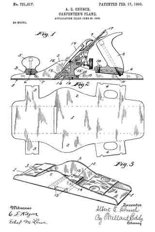
Figure 1 is a central longitudinal section of a plane which is constructed in accordance with those principles. Fig. 2 is a plan view of a stock-blank, being a flat sheet of metal, preferably cold-rolled steel, stamped out in suitable shape to be formed into the stock of said plane by bending. Fig. 3 is a perspective view of the plane-stock, including the frog-seat, in position.
In the views the sole of the stock and the side walls or flanges of the same are indicated, respectively, by the numerals 1 and 2. The wings 3 and 3 of the blank (shown in Fig. 2) make a terminal abutment with each other when the blank is bent into shape, and thus constitute bridge 3, which is shown in the remaining figures. In like manner the wings 4 of the blank become the bridge 4 of the stock. Bridge 3 serves as a slightly-yielding and resilient support for the knob 5, which is fastened thereto by means of a screw 6 and nut 7, and in like manner bridge 4 constitutes a similar seat for the handle 8, which is secured thereto by the screws 9 and 10 and the screw-plate 11. The frog-seat 12 is firmly secured to the stock in its proper position by pins 13 and dowel 14 and reaches from one flange 2 to the other, as shown in Fig. 3. Neither the frog 15, which is adjustably secured to seat 12 by screws 16, nor the plane-iron 17, the plane-iron cap 18, and the cap 19, all which are exhibited in a familiar form in Fig. 1, require any particular description, as their special form does not affect the essence of my invention.
The described construction of the stock from a single flexible sheet is simple and easy in respect of the process of manufacture, and the described mounting of the knob and the handle of the plane upon raised bridges of the stock renders the manipulation of the tool smooth and easy to the hand of the carpenter.
Such being the construction and operation of my improved carpenters’ planes, I claim as my invention —
l. In a plane-stock, a sole, and two flanges bent up respectively from the side edges of the sole, in combination with a transverse bridge, from one of said flanges to the other, all formed from a single piece of sheet metal, substantially as and for the purpose specified.
2. A plane-stock, formed of a single sheet of metal, and consisting of a sole, two flanges bent up respectively from the opposite edges of the sole, and two bridges from one of said flanges to the other, in combination with a knob and a handle which are mounted upon said bridges respectively, substantially as and for the purpose specified.
3. In a plane-stock, a thin sole, and two thin flanges bent up respectively from the side edges of the sole, in combination with a bridge from one of said flanges to the other, all formed from a continuous piece of sheet metal, and provided with a knob or handle which is mounted upon said bridge, substantially as and for the purpose specified.
4. A plane-stock, formed from a single sheet of metal, stamped out, and consisting of a flat sole, two flanges bent up respectively from opposite edges of such sole, and two bridges between said flanges, substantially as and for the purpose specified.
In testimony whereof I hereunto set my name in the presence of two witnesses.
ALBERT E. CHURCH.
Witnesses:
WILLARD EDDY,
JAMES MATHER.