| PLEASE NOTE: The images presented on this page are of low resolution and, as a result, will not print out very well. If you wish to have higher resolution files then you may purchase them for only $2.95 per patent by using the "Buy Now" button below. All purchases are via PayPal. These files have all been cleaned up and digitally enhanced and are therefore suitable for printing, publication or framing. Each zip package contains all the images below (some packages may contain more), and purchased files can be downloaded immediately. |
UNITED STATES PATENT OFFICE.
_________________
JAMES W. BRADY, OF SOUTH BEND, INDIANA.
GUIDE FOR PLANES.
_________________
SPECIFICATION forming part of Letters Patent No. 729,725, dated June 2, 1903.
Application filed June 23, 1902. Serial No. 112,775. (No model.)
_________________
To all whom it may concern:
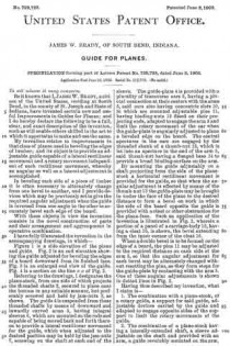
Be it known that I, JAMES W. BRADY, a citizen of the United States, residing at South Bend, in the county of St. Joseph and State of Indiana, have invented certain new and useful Improvements in Guides for Planes; and I do hereby declare the following to be a full, clear, and exact description of the invention, such as will enable others skilled in the art to which it appertains to make and use the same.
My invention relates to improvements in that class of planes used in beveling the edges of lumber; and its object is to provide an adjustable guide capable of a lateral rectilinear movement and a rotary movement independent of such rectilinear movement, whereby an angular as well as a lateral adjustment is accomplished.
In beveling each side of a piece of timber it is often necessary to alternately change from one bevel to another, and I provide devices which may be previously set to give the required angular adjustment when the guide is reversed from one angle to the other to accurately bevel each edge of the board.
With these objects in view the invention consists in the novel construction of parts and their arrangement and aggroupment in operative combination.
I have fully illustrated the invention in the accompanying drawings, in which —
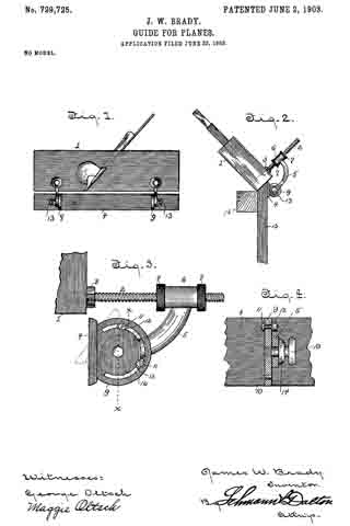
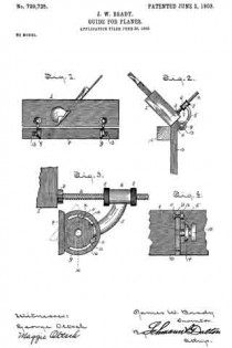
Figure 1 is a side elevation of the plane and guide. Fig. 2 is an end elevation showing the guide adjusted for beveling the edges of a board downward from its finished face. Fig. 3 is an enlarged end view of the guide. Fig. 4 is a section on the line x x of Fig. 3.
Referring to the drawings, 1 designates the plane-stock, from one side of which projects the threaded shafts 2, secured in place near the bottom in any suitable manner, but preferably screwed and held by jam-nuts 3, as shown. The guide 4 is suspended from these threaded shafts by means of downward and inwardly curved arms 5, having integral sleeves 6, which are mounted on the rods and capable of being moved back and forth thereon to provide a lateral rectilinear movement for the guide, which when adjusted to the desired position may be held by the jam-nuts 7, screwing on the shaft at each end of the sleeve. The guide-plate 4 is provided with a plurality of transverse ears 9, having a pivotal connection at their centers with the arms 5, said ears also having concentric slots 10, in which are mounted adjustable pins 11, having binding-nuts 12 fitted on their projecting ends, adapted to engage the arm 5 and limit the rotary movement of the ear when the guide-plate is augularly adjusted to plane a beveled edge on the board. The central apertures in the ears are engaged by the threaded shank of a thumb-nut 13, which is let into an aperture in the end of the arm 5, said thumb-nut having a flanged base 14: to provide a broad binding-surface on the arm.
By mounting the guide adjustably on a shaft projecting from the side of the plane-stock a horizontal rectilinear movement is provided for the guide, so that when the angular adjustment is effected by means of the thumb-nut 13 the guide-plate maybe brought in under the face of the plane to the desired distance to form a bevel on work in which the side of the board opposite the guide is provided with a cleat or other obstruction for the plane-face. Such an application of the invention is illustrated in Fig. 2, wherein a portion of a panel of a carriage-body 15, having a cleat 16, is shown, the bevel extending from the inner corner of the cleat 16. I When a double bevel is to be formed on the edge of a board, the pins 11 may be adjusted to the required distance on each side of the arm 5, so that the angular adjustment for each bevel may be alternately changed without resetting the pins, as they form stops for the guide-plate by contacting with the arm 5. One of these angular adjustments is shown in dotted lines in Fig. 3.
Having thus described my invention, what I claim is —
1. The combination with a plane-stock, of a rotary guide, a support for said guide, adjustable devices carried by the guide and adapted to engage opposite sides of the support to limit the rotary movements of the guide.
2. The combination of a plane-stock having a laterally-extended shaft, a sleeve adjustable on the shaft and provided with an arm, a guide revolubly mounted on the arm, and adjustable devices carried by the guide to regulate the rotary movements of the same.
3. In a device of the class described, the combination with the plane-stock having screw-shafts projecting laterally therefrom, sleeves slidable on said shaft, jam-nuts to hold the sleeves, arms depending from the sleeves, a guide-plate having ears pivotally connected to said arms, slots in the ears, and adjustable stops in the slots on each side of the arm, whereby two angular adjustments may be made without changing the position of the stops.
4. In a device of the class described, the combination with the plane-stock having shafts projecting laterally therefrom, of a plane-guide horizontally adjustable on said shafts and consisting of arms and a guide-plate having ears pivoted to said arms, and means carried by the ears on each side of the arms to limit the rotary movement of the guide-plate when angularly adjusted.
In testimony whereof I affix my signature in presence of two witnesses.
JAMES W. BRADY.
Witnesses:
GEORGE OLTSCH,
MAGGIE OLTSCH.


