
| PLEASE NOTE: The images presented on this page are of low resolution and, as a result, will not print out very well. If you wish to have higher resolution files then you may purchase them for only $2.95 per patent by using the "Buy Now" button below. All purchases are via PayPal. These files have all been cleaned up and digitally enhanced and are therefore suitable for printing, publication or framing. Each zip package contains all the images below (some packages may contain more), and purchased files can be downloaded immediately. |
UNITED STATES PATENT OFFICE.
_________________
ALIX W. STANLEY, OF NEW BRITAIN, CONNECTICUT, ASSIGNOR TO
STANLEY RULE & LEVEL COMPANY, OF NEW BRITAIN,
CONNECTICUT, A CORPORATION OF CONNECTICUT.
PLANE.
_________________
SPECIFICATION forming part of Letters Patent No. 738,500, dated September 8, 1903.
Application filed February 11, 1903. Serial No. 142,844. (No model.)
_________________
To all whom it may concern:
Be it known that I, ALIX W. STANLEY, a citizen of the United States, residing at New Britain, in the county of Hartford, State of Connecticut, have invented certain new and useful Improvements in Planes, of which the following is a full, clear, and exact description.
My invention relates to planes, and particularly to that class of planes adapted to be used on curved surfaces, sometimes termed “circular planes.” In planes of this character the base or sole portion is so arranged that it maybe made to assume different curvatures to cause the plane to properly fit to surfaces of different degrees of curvature upon which it is desired to operate the tool. These curvatures may be either concaved or convex. In the particular form shown the sole or base is made of flexible material, such as sheet metal or spring-steel. When adjusting the sole to the desired curvature, it is most desirable that said adjustment may be effected accurately and quickly.
To that end, therefore, the object of my invention is to provide simple, effective, and durable means whereby the plane may be so adjusted that exactly the proper curvature will be given to the sole without requiring the user to make any preliminary trials to ascertain whether the plane fits the curved surface on which it is to be used.
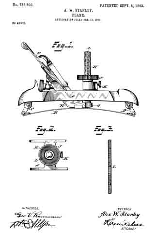
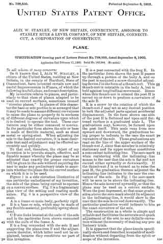
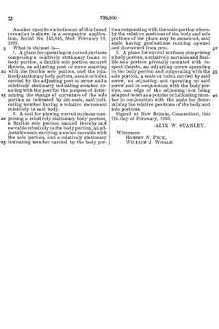
Figure 1 is a side elevation illustrative of one particular embodiment of my invention, the sole of the plane being curved to operate on a convex surface. Fig. 2 is a fragmentary plan view of the setting and reading mechanism. Fig. 3 is a perspective view of the scale.
A is a frame or main body, perfectly rigid.
B is a base or sole, which may be made of any flexible material, preferably spring sheet-steel.
C D are links located at the ends of the sole and in the particular form shown connected with the ends of the frame A.
E is a frog connected with the sole B and supporting the plane-iron F and the adjustments therefor, which latter need not be explained, because they constitute no part of this invention.
H is a post connected with the frog E. In the particular form shown the post H passes up through a portion of the body A, and on the post is mounted a screw-threaded adjusting device J in the form of a thumb-nut. This thumb-nut is rotatable in the body A, but is held against longitudinal movement. Hence when this thumb-nut is rotated the post H is moved up or down to produce a curvature of the sole B.
K is a screw by the rotation of which the thumb-nut J may set at any desired position to lock the adjusted parts against accidental displacement. In the form shown one side of the post H is flattened and upon said flattened surface is a graduated scale L. The graduations may, however, be formed upon the post itself. This scale runs from zero upward and downward, the graduations being proper to indicate to the user the exact curvature of the sole. These graduations are read on the line of the upper surface of the thumb-nut J, since that member is relatively stationary and its upper surface constitutes a convenient indicating-line. The zero-mark when registering with the indicating line means to the user that the sole is flat and not curved either upwardly or downwardly. If the thumb-nut J is so turned as to raise the post H, the graduation thereon adjacent the indicating-line indicates to the user the curvature of the sole. In Fig. 1 the zero-mark will be seen to be above the indicating-line. Hence the sole is curved upwardly, so that the plane may be used on a convex surface. Were the post depressed, so that some graduation above the zero-mark should lie adjacent to the indicating-line, it would show to the user that the sole is curved downwardly. The particular graduation would indicate to him the exact curvature of the sole.
The construction as a whole is simple and reliable and facilitates the accurate and quick adjustment of the sole to any definite curvature without the necessity of making any preliminary trials.
It is apparent that the plane herein specifically shown and described is capable of modification without departing from the spirit or scope of the invention.
Another specific embodiment of this broad invention is shown in a companion application, Serial No. 142,845, filed February 14, 1903.
What is claimed is —
1. A plane for operating on curved surfaces comprising a relatively stationary frame or body portion, a flexible sole portion secured thereto, an adjusting post or screw coacting with the flexible sole portion, and the relatively stationary body portion, a scale or index carried by the adjusting post or screw and a relatively stationary indicating member coacting with the post for the purpose of determining the change of curvature of the sole portion as indicated by the scale, said indicating member having a rotative movement relatively to said body.
2. A tool for planing curved surfaces comprising a relatively stationary body portion, a flexible sole portion carried thereby and movable relatively to the body portion, an adjustable scale-carrying member movable with the sole portion, and a relatively stationary indicating member carried by the body portion cooperating with the scale portion whereby the relative positions of the body and sole portions of the plane may be measured, said scale having graduations running upward and downward from zero.
3. A plane for curved surfaces comprising a body portion, a relatively movable and flexible sole portion pivotally mounted with respect thereto, an adjusting-screw operating in the body portion and cooperating with the sole portion, a scale or index carried by said screw, an adjusting-nut operating on said screw and in conjunction with the body portion, one edge of the adjusting-nut being adapted to act as a pointer or indicating member in conjunction with the scale for determining the relative positions of the body and sole portions.
Signed at New Britain, Connecticut, this 7th day of February, 1903.
ALIX W. STANLEY.
Witnesses:
ROBERT N. PECK,
WILLIAM J. WORAM.