
| PLEASE NOTE: The images presented on this page are of low resolution and, as a result, will not print out very well. If you wish to have higher resolution files then you may purchase them for only $2.95 per patent by using the "Buy Now" button below. All purchases are via PayPal. These files have all been cleaned up and digitally enhanced and are therefore suitable for printing, publication or framing. Each zip package contains all the images below (some packages may contain more), and purchased files can be downloaded immediately. |
UNITED STATES PATENT OFFICE.
_________________
ALEXANDER MASON, OF SALEM, MASSACHUSETTS.
MATCHING-PLANE.
_________________
SPECIFICATION forming part of Letters Patent No. 748,199, dated December 29, 1903.
Application filed March 20, 1903. Serial No. 148,745. (No model.)
_________________
To all whom it may concern:
Be it known that I, ALEXANDER MASON, a citizen of the United States, residing at Salem, in the county of Essex and State of Massachusetts, have invented certain new and useful Improvements in Matching-Planes; and I do hereby declare the following to be a full, clear, and exact description of the invention, such as will enable others skilled in the art to which it appertains to make and use the same.
This invention relates to matching-planes; and it consists in the novel construction and combination of the parts hereinafter fully described and claimed.
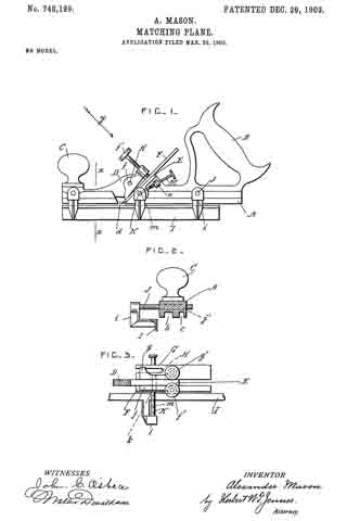
In the drawings, Figure 1 is a side view of the matching-plane. Fig. 2 is a cross-section taken on the line x x in Fig. 1. Fig. 3 is a partial plan view showing the clamping-levers and looking in the direction of the arrow y in Fig. 1.
A is the body of the plane, provided with a handle B at one end and a knob C at the other end. The body portion A has a broad groove b and a narrow groove c in its under side, and D is a longitudinal rib on the upper side of the body portion.
E is an inclined support for the blades, which also projects on the upper side of the body portion, and d represents slots or notches in the body portion A for the blades to project through.
F is a single cutting-blade, and G is a forked cutting-blade. These blades are laid upon the support E, one on each side of the rib D, and are clamped in position by means of two clamping-levers f and g, which are pivoted on the end portions of a pin H, which is secured in the rib D. These clamping-levers are provided at their upper ends with thumb-screws f’ and g’, which bear against the blades, so that the lower ends of the levers clamp the said blades securely in position.
I is a guide for the plane. This guide is provided with projecting brackets i at its end and middle portions. The end brackets carry bars J, which are slidable in guide-holes j in the body of the plane. The middle bracket carries a bar K, which is slidable in a hole k in the body of the plane and which is provided with a series of cross-holes m.
M is a spring-pressed stop-pin which is slidable in a lug n on the body of the plane and which engages with the said cross-holes. The guide is slid so as to suit the work, and it is then secured in position by means of the said stop-pin.
The two blades form three separate cutters, and they will tongue and groove boards of widely-varying thickness in a very satisfactory manner.
What I claim is —
In a matching-plane, the combination, with a body portion, of a guide for the said body portion provided with projecting brackets at its middle and end portions, bars projecting from the said end brackets and slidable in cross-holes in the said body portion, a bar projecting from the middle bracket and provided with a series of cross-holes and slidable in a hole in the said body portion, and a spring-actuated stop-pin carried by the said body portion and engaging with the cross-holes of the said bar.
In testimony whereof I affix my signature in presence of two witnesses.
ALEXANDER MASON.
Witnesses:
ALICE J. MURRAY,
FRED. K. DAGGETT.