
| PLEASE NOTE: The images presented on this page are of low resolution and, as a result, will not print out very well. If you wish to have higher resolution files then you may purchase them for only $2.95 per patent by using the "Buy Now" button below. All purchases are via PayPal. These files have all been cleaned up and digitally enhanced and are therefore suitable for printing, publication or framing. Each zip package contains all the images below (some packages may contain more), and purchased files can be downloaded immediately. |
UNITED STATES PATENT OFFICE.
_________________
ALONZO ST. JOHN, OF LOWVILLE, NEW YORK, ASSIGNOR OF ONE-HALF TO F. N. LOSON, OF LOWVILLE, NEW YORK.
BENCH-PLANE.
_________________
SPECIFICATION forming part of Letters Patent No. 779,246, dated January 3, 1905.
Application filed February 6, 1904. Serial No. 192,420.
_________________
To all whom it may concern:
Be it known that I, ALONZO ST. JOHN, a citizen of the United States, residing at Lowville, in the county of Lewis and State of New York, have invented certain new and useful Improvements in Bench-Planes; and I do declare the following to be a full, clear, and exact description of the invention, such as will enable others skilled in the art to which it appertains to make and use the same, reference being had to the accompanying drawings, and to the letters of reference marked thereon, which form a part of this specification.
This invention relates to new and useful improvements in bench-planes, and the object of the invention is to produce a device of this character which will be simple in construction and having means for easily and rapidly adjusting the knife; and it consists, essentially, in the provision of a cam-shaped member, adapted to cause the knife-holding block to securely clamp the knife in an adjusted position while the operator still has hold of the handle of the stock of the plate, and in the provision of means for regulating the gage of the knife.
My invention consists, further, in various details of construction, combinations, and arrangements of parts, which will be hereinafter fully described, and then specifically deined in the appended claims.
I illustrate my invention in the accompanying drawings, which, with the letters of reference marked thereon, form a part of this application, and in which similar letters of reference indicate like parts in the views, in which —
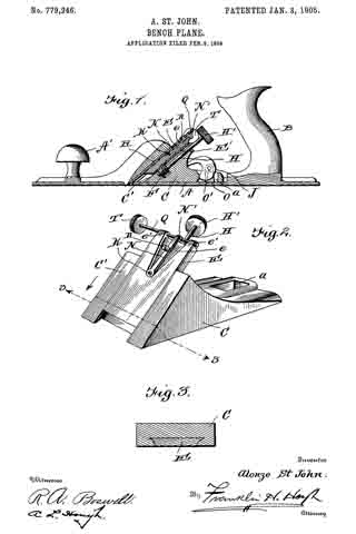
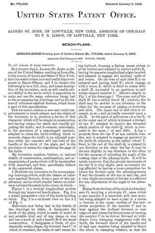
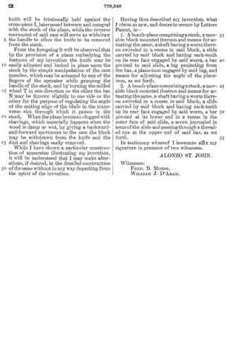
Figure 1 is a vertical longitudinal section through my improved bench-plane. Fig. 2 is a detail perspective view of the knife-holding block. Fig. 3 is a sectional view on line 3 3 of Fig. 1.
Reference now being had to the details of the drawings by letter, A designates the stock of the plane, which is made of metal of any suitable kind and of any shape or size and has a knob A’ and a handle B of the usual construction. C designates a block of substantially wedge shape, the forward face C’ of which is recessed, the walls of said recess being inclined, forming a flaring recess widest at its bottom and adapted to receive a slide E, having its opposite longitudinal edges beveled and adapted to engage the inclined walls of said recess. On the rear of said slide E is an integral rack having teeth E’, which engage with a worm F, which is fixed to rotate with a shaft H, journaled in an aperture in said wedge-shaped member C. (Shown clearly in Fig. 1 of the drawings.) The outer end of the shaft H has a milled wheel H’, whereby the shaft may be carried in one direction or the other for the purpose of raising or lowering said slide. The upper end of said slide is recessed, as at e, and pivotally mounted upon a pin K. At the apex of said recess e is a bar N, at the outer end of which is formed a threaded eye N ’, adapted to receive the threaded shank portion of the shaft Q, which is journaled in the arms e’ of said slide. A lug n projects from the bar N at any suitable location and is adapted to engage an aperture in the knife R, whereby as the milled wheel T, fixed to the end of the shaft Q, is rotated in one direction or the other the bar N may be thrown slightly in one direction or the other for the purpose of adjusting the angle of the cutting edge of the planing-knife. It will be noted, however, that the pivotal movement of the bar N is very slight, such movement being afforded by having a loose connection between the threads upon the adjusting-screw T and the threads of the eye in said bar, and a very slight movement of the bar is sufhcient for any adjustment of the angle of the plane-iron.
Rising from the base of the stock is a bracket-arm O, carrying a pivot-pin O’, upon which a cam member J is mounted, said cam member being adapted to have a play in a recess a, formed in the upper surface of the horizontal projection of the member C and to bear against the inclined forward or rear edges of said recess for the purpose of causing the member C to be driven forward or withdrawn from clamping engagement with the knife, the forward throw of the handle end of said cam member being adapted to throw the block in clamping relation, so that the knife will be frictionally held against the cross-piece I, interposed between and integral with the stock of the plane, while the reverse movement of said cam will serve to withdraw the handle to allow the knife to be removed from the stock.
From the foregoing it will be observed that by the provision of a plane embodying the features of my invention the knife may be easily adjusted and locked in place upon the stock by the simple manipulation of the cam member, which may be actuated by one of the fingers of the operator while grasping the handle of the stock, and by turning the milled wheel T in one direction or the other the bar N may be thrown slightly to one side or the other for the purpose of regulating the angle of the cutting edge of the blade to the transverse slot through which it passes in the stock. When the plane becomes clogged with shavings, which especially happens when the wood is damp or wet, by giving a backward-and-forward movement to the cam the block may be withdrawn from the knife and the dust and shavings easily removed.
While I have shown a particular construction of apparatus illustrating my invention, it will be understood that I may make alterations, if desired, in the detailed construction of the same without in any way departing from the spirit of the invention.
Having thus described my invention, what I claim as new, and desire to secure by Letters Patent, is —
1. A bench-plane comprising a stock, a movable block mounted thereon and means for actuating the same, a shaft having a worm thereon swiveled in a recess in said block, a slide carried by said block and having rack-teeth on its rear face engaged by said worm, a bar pivoted to said slide, a lug projecting from the bar, a plane-iron engaged by said lug, and means for adjusting the angle of the plane-iron, as set forth.
2. A bench-plane comprising a stock, a movable block mounted thereon and means for actuating the same, a shaft having a worm thereon swiveled in a recess in said block, a slide carried by said block and having rack-teeth on its rear face engaged by said worm, a bar pivoted at its lower end in a recess in the outer face of said slide, a screw journaled in arms of the slide and passing through a threaded eye at the upper end of said bar, as set forth.
In testimony whereof I hereunto affix my signature in presence of two witnesses.
ALONZO ST. JOHN.
Witnesses:
FRED. B. MORSE,
WILLIAM J. D’ARAM.