
| PLEASE NOTE: The images presented on this page are of low resolution and, as a result, will not print out very well. If you wish to have higher resolution files then you may purchase them for only $2.95 per patent by using the "Buy Now" button below. All purchases are via PayPal. These files have all been cleaned up and digitally enhanced and are therefore suitable for printing, publication or framing. Each zip package contains all the images below (some packages may contain more), and purchased files can be downloaded immediately. |


UNITED STATES PATENT OFFICE.
_________________
ROBERT HUNTER, OF SPOKANE, WASHINGTON.
REVERSIBLE HANDLE ATTACHMENT FOR PLANES.
_________________
816,980. Specification of Letters Patent. Patented April 3, 1906.
Application filed March 28, 1905. Serial No. 252,596.
_________________
To all whom it may concern:
Be it known that l, ROBERT HUNTER, a citizen ofthe United States, and a resident of Spokane, in the county of Spokane and State of Washington, have made certain new and useful Improvements in Handle Attachments for Planes, of which the following is a specification.
My invention is an improvement in that class of carpenter’s or hand planes which are provided with handles adapted to be shifted laterally, so that the plane may be used in angles or corners where it would be otherwise impracticable.
My invention is embodied in certain novel features of construction, arrangement, and combinations of parts, as hereinafter described and claimed, the same being illustrated in the accompanying drawings, in which —
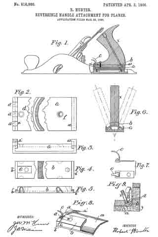
Figure 1 is in part a side view and in part a section of a hand-plane provided with my improved attachment. Fig. 2 includes both the plan view and cross-section of the base-piece upon which the handle of the plane is adapted to be adjusted laterally. Fig. 3 is a side view of the parts shown in Fig. 2. Fig. 4 includes a plan view and cross-section of the movable piece to which the handle of the plane is secured. Fig. 5 is a side or edge view of the part shown in Fig. 4. Fig. 6 is a diagrammatic sectional view illustrating the lateral adjustment or shifting of the handle. Fig. 7 includes a side view and plan view of a spring-catch employed for locking the movable part to the base or fixed part. Fig. 8 is a perspective view illustrating the arrangement and locking of the movable piece on the fixed or base piece. Fig. 9 is a view illustrating the practical operation of the plane provided with my improved attachment.
a indicates a base-piece, which is hired in position on the rear portion of the metal plane between its sides. As shown in Fig. 1, it is secured by means of two screws whose heads are countersunk. The upper side of this base-piece is constructed on the are of a circle extending between the side of the body of the plane and described from a center located below the base of said body. The said base-piece is provided with upturned end portions having inwardly-projecting flanges a’ a2.
The part b (see Figs. 4, 5, 8,) is about half the width of the base-piece a and is secured to the base of the handle x by means of two screws, as illustrated in Fig. 1. The under side ot the movable piece b is curved laterally corresponding to the curvature or convexity of the fixed base-piece a, so that the two fit together, as indicated in Figs. 6 and 8. The ends of the movable piece b are rabbeted, thus producing projections b’, which are adapted to fit and slide under the flanges a’ a2 of the base-piece a. The parts a b are fitted together in such a manner that there is no looseness or play, yet the part b is adapted to slide easily. For the purpose of locking the part b in any required adjustment I provide a spring-catch, (see Figs. 7 and 8,) which comprises a base-piece having an upwardly and forwardly projecting finger-piece C. The catch is secured flush in a recess in the upper side of the part b by means of the forward screw, which also passes through the handle, as indicated in Fig. 1. The free end of the spring-catch is adapted to enter notches d, (see Figs. 2 and 8,) which are formed in the upper side of the arc-shaped front flange a’. There are three of these notches, one being arranged in the center and the others laterally therefrom, so that three adjustments of the handle at are provided for — that is to say, the handle may be set and locked in the center, which would be its norrnal position, and it may be adjusted laterally, so as to incline to the right or left, as conditions require.
ln Fig. 9 the handle x is shown usted to the left, so that the body of the plane may be placed and operated close to the side of the vertical portion of the wooden block y. In other words, the handle may be inclined entirely to one side of a vertical longitudinal plane, so that the hand of the operator using the plane is farther from the vertical than it would be if the handle were pivoted at points within the body of the plane.
It is apparent that by pulling upon the finger-piece C of the spring-catch the latter may be disengaged from any of the notches d, and then the handle so may be shifted laterally to the right or left and locked in another position.
What I claim is —
1. In a plane of the class indicated, the combination, with the body of the same, of a fixed base-piece having its upper side formed upon the are of a circle extending between the sides of the plane and described from a point outside the body of the plane, and having upturned end portions which are undercut, a movable piece fitted to the curved surface of the base-piece and having projecting end portions adapted to fit and slide in such upturned under-cut portions, means for locking the two parts together, and a handle secured to said movable piece, substantially as described.
2. In a plane of the class indicated, the combination with the fixed base-piece having its upper side curved corresponding to a segment of a cylinder, and provided with upturned end flanges, one of which has a series of notches, the movable piece fitted and adapted to slide upon the curved base-piece, a spring-catch secured to the movable piece and adapted to engage any of the said notches, and a handle secured to the movable base-piece, substantially as described.
In testimony whereof I have signed my name to this specification in the presence of two witnesses.
ROBERT HUNTER.
Witnesses:
J. W. McKUNE,
J. C. WILLIAMS.