| PLEASE NOTE: The images presented on this page are of low resolution and, as a result, will not print out very well. If you wish to have higher resolution files then you may purchase them for only $2.95 per patent by using the "Buy Now" button below. All purchases are via PayPal. These files have all been cleaned up and digitally enhanced and are therefore suitable for printing, publication or framing. Each zip package contains all the images below (some packages may contain more), and purchased files can be downloaded immediately. |
UNITED STATES PATENT OFFICE.
_________________
JUSTUS A. TRAUT, OF NEW BRITAIN, CONNECTICUT, ASSIGNOR TO STANLEY RULE &
LEVEL COMPANY, OF NEW BRITAIN, CONNECTICUT, A CORPORATION OF CONNECTICUT.
BENCH-PLANE.
_________________
830,541. Specification of Letters Patent. Patented Sept. 11, 1906.
Application filed May 26, 1906. Serial No. 318,812.
_________________
To all whom it may concern:
Be it known that I, JUSTUS A. TRAUT, a citizen of the United States, residing at New Britain, county of Hartford, Connecticut, have invented certain new and useful Improvements in Planes, of which the following is a full, clear, and exact description.
My invention relates to improvements in tools, and particularly planes for carpenters’ and joiners’ use.
The object of the invention is to provide a stop or gage for limiting the cutting depth and steadying the plane when in operation.
Various gages and stops have previously been employed in tools of this character, but for some classes of work they fail to give proper support to the plane when in operation.
The preferred form of the invention is illustrated in the accompanying three sheets of drawings.
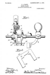
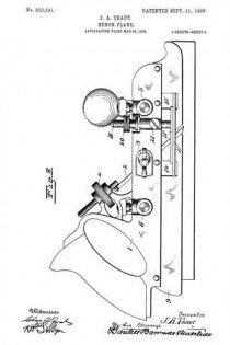
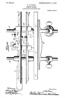
Figure 1 is an end view of a plane embodying the improvements of my invention. Fig. 2 is a detail perspective view of a part of the gage. Fig. 3 is a side view of a plane with gage attached. Fig. 4 is a bottom plan view.
1 is the main body or handle member.
2 is the plane-iron having a suitably-formed cutting edge in accordance with the cross-section of the product desired. This iron is clamped in place by a suitable mechanism, such as 3, and may be adjusted by a suitable mechanism, such as 4.
5 and 6 are cross-rods clamped to the body in a suitable manner.
7 is an auxiliary clamping and supporting member for the plane-iron, which is clamped on the rods 5 and 6 by suitable mechanism.
8 is a fence customarily employed with planes of this character for guiding it laterally in operation. The main and auxiliary portions of the plane are provided with guide-flanges 9 and 10. A plane-iron of any width may be employed with this tool, the body and auxiliary members being adjusted laterally with respect to one another.
11 is the gage or stop the use of which my invention particularly contemplates. This stop has laterally-extending arms 12 and 13, which project through openings, such as 14 and 15, in the guide-flanges 9 and 10.
16 is a screw-threaded post having a foot 17, to which the gage 11 is secured by means of screws 18 and 19.
The post and gage may be vertically adjusted by the screw 20 and clamped in position by the screw 21. When the gage is being vertically adjusted, it is guided and prevented from rotating on its post by reason of its construction and coaction with the guide-flanges 9 and 10. By reason of the bearing-surfaces provided by the arms 12 and 13 in front and in rear ofthe cutting-iron and the lateral extensions outside of each guide-flange the tool is prevented from tilting forward and back or sidewise when in operation.
The gage may be adjusted to suit the depth of cut desired and may be readily removed upon releasing the screws 18 and 19, in which event the foot 17 acts as a gage, which maybe adjusted for work requiring the gage only on one side. The arms 12 and 13 being formed in one piece with the main body 11 of the gage, the entire bearing area remains in a single plane and is consequently adjusted vertically with uniformity in front and in rear of the plane-iron. This is an advantage which would not be present were the two arms 12 and 13 carried by separate adjusting-posts.
What I claim is —
1. In a plane, a body, auxiliary members having depending guide-flanges with passages in said flanges, and a gage extending laterally through said passages.
2. In a plane, a body and auxiliary members laterally adjustable with relation to one another and adapted to support a plane-iron, a vertically-adjustable post, and a gage carried thereby having members extending in front and in the rear of the plane-iron position and laterally beyond the edges of the plane-iron.
3. In a plane, a body having a depending flange, a plane-iron carried by the body, an adjustable post carried by the body, and a gage carried by said post having an arm extending through the flange in front of the plane-iron.
4. In a plane, a body, an iron clamped thereto, a depending iiange from said body, an auxiliary member laterally adjust able with respect thereto, a depending guide-flange carried by said auxiliary member, and a vertically-adjustable gage in the rear of the plane-iron position extending through said flanges.
5. In a plane, main and auxiliary sections, depending flanges carried thereby, a plane-iron held between said sections, a vertically-adjustable post having a foot, and a gage removably secured to said foot and having an arm extending through said flanges.
6. In a plane, main and auxiliary sections, depending flanges carried thereby, a plane-iron held between said sections, a vertically-adjustable post having a foot, and a gage removably secured to said foot and having arms extending through said flanges in front and in the rear of the plane-iron.
7. As an article of manufacture, a plane-gage attachment comprising a body, means of attachment to a plane, and laterally-extending arms carried by the body spaced apart from each other and lying in the same plane with the body.
JUSTUS A. TRAUT.
Witnesses:
W. J. WORAM,
H. S. WALTER.

