| PLEASE NOTE: The images presented on this page are of low resolution and, as a result, will not print out very well. If you wish to have higher resolution files then you may purchase them for only $2.95 per patent by using the "Buy Now" button below. All purchases are via PayPal. These files have all been cleaned up and digitally enhanced and are therefore suitable for printing, publication or framing. Each zip package contains all the images below (some packages may contain more), and purchased files can be downloaded immediately. |
UNITED STATES PATENT OFFICE.
_________________
JUSTUS A. TRAUT, OF NEW BRITAIN, CONNECTICUT, ASSIGNOR TO STANLEY RULE &
LEVEL COMPANY, OF NEW BRITAIN, CONNECTICUT, A CORPORATION OF CONNECTICUT.
SCRAPING-TOOL.
_________________
837,978. Specification of Letters Patent. Patented Dec. 11, 1906.
Application filed May 26, 1906. Serial No. 318,811.
_________________
To all whom it may concern:
Be it known that I, JUSTUS A. TRAUT, a citizen of the United States, residing at New Britain, Hartford county, Connecticut, have invented certain new and useful Improvements in Scraping-Tools, of which the following is a full, cllear, and exact description.
My invention relates to improvements in woodworking-tools; and it consists in an improved scraper, the construction of which is such that it may be used, if desired, with an ordinary plane, merely substituting the same for the usual plane-iron. In this connection the device is capable of all of the adjustments to which the usual plane-iron is adapted and may be employed with an unusual degree of success.
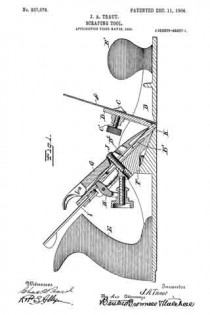
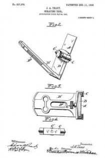
In the accompanying drawings, Figure 1 is a longitudinal section of an ordinary plane-body fitted with my improved scraper. Fig. 2 is a perspective view of the scraper and scraper frame or carrier. Fig. 3 is a plan view of the same. Fig. 4. is a detail view of a clamping member.
I will first describe the scraper and scraper-carrier.
A is the scraper-blade, having the usual sharpened edge.
B B’ are two arms of the frame or scraper-carrier arranged to carry the blade A. As shown, these arms B B’ are arranged in the form of a wedge or a V — that is, the outer bearing-surfaces of the same form a V. The plane-iron A is clamped against the outer bearing-surface of the arm B by means of any suitabie clamping device — for example, the member C, carrying the clamping-screw C’. The arm B’ is so constructed and arranged that it may be readily applied to the plane-iron support or “frog” of a plane, the connection being preferably such that the various adjusting devices commonly found on planes will be available for the purpose of adjusting the position of the cutting edge of the scraper-blade in the throat of the plane. In the drawings, Fig. 1, I have shown the scraper-frame as it would appear in place on an ordinary plane. In this view, D indicates the main body of the plane. E E’ are the handles. F is the usual frog on the plane-iron support. G is the usual clamping- plate cooperating with the screw-post J. H I are adjusting-levers such as commonly employed in planes and by which the plane-iron may be given any desired adjustment. These levers need not be explained in detail, since their operation is well understood.
On referring to Fig. 1 it will be seen that the scraper-frame is clamped to the frog precisely as the ordinary plane-iron is clamped thereon, and the edge of the scraper-blade A will project through the throat or passage in the sole of the plane in the same manner as will the edge of the plane-iron, excepting that it will stand at a substantially different angle. The arm B of the scraper-frame is cut back or recessed transversely near its lower end, as indicated at K, to give a clearance back of the cutting edge of the scraper-blade. This is done to permit the cutting edge of the scraper to yield slightly and is productive of the most effective results in operation. While the scraper-frame is primarily adapted for use in connection with the plane, nevertheless the frame or carrier will itself afford a convenient grip when the scraper is used independently of a plane-body. The angle of the bearing-surfaces of the arms B B’ (indicated in the drawings) is that best adapted for the most successful results when the scraper is to be used in connection with the plane; but this angle, of course, may be varied to some extent at will. In the arm B’ of the scraper-frame a central longitudinal passage B2 adords clearance for the post J.
L is the usual cam by which the clamping-plate G may be set down hard, so as to hold the scraper-frame firmly on its seat.
What I claim is —
1. As an article of manufacture, a scraper attachment for a plane, comprising a body having two arms inclined relatively to each other, a scraper-blade, means for adjustably securing the scraper-blade to one of said arms, the other arm having a longitudinal recess and a transverse recess above said longitudinal recess, said recesses being adapted to accommodate mechanism of a plane for effecting lateral and vertical adjustment respectively.
2. As an article of manufacture, a scraper attachment for a plane comprising, a body having two arms arranged at an angle relatively to each other and furnishing two bearing-surfaces, one for contact with the plane-support, the other for the reception of a scraper-blade, a scraper-blade, means for adjustably securing the same to the said bearing-face, said bearing-face at and near the meeting angle of the two arms being recessed to afford clearance for the blade adjacent to its cutting edge.
JUSTUS A. TRAUT.
Witnesses:
H. S. WALTER,
L. E. CLEMONS.


