
| PLEASE NOTE: The images presented on this page are of low resolution and, as a result, will not print out very well. If you wish to have higher resolution files then you may purchase them for only $2.95 per patent by using the "Buy Now" button below. All purchases are via PayPal. These files have all been cleaned up and digitally enhanced and are therefore suitable for printing, publication or framing. Each zip package contains all the images below (some packages may contain more), and purchased files can be downloaded immediately. |

UNITED STATES PATENT OFFICE.
_________________
WILLIAM F. ARNOLD, OF OAKLAND, CALIFORNIA.
CARPENTER’S PLANE.
_________________
840,418. Specification of Letters Patent. Patented Jan. 1, 1907.
Application filed September 12, 1906. Serial No. 334,372.
_________________
To all whom it may concern:
Be it known that I, WILLIAM F. ARNOLD, a citizen of the United States, residing at Oakland, in the county of Alameda and State of California, have invented certain new and useful Improvements in Carpenters’ Planes, of which the following is a specification.
My invention relates to the class of carpenters’ planes, and is applicable to smoothers, jointers, or jack-planes.
The objects of my invention are to provide a better bearing in the stock for the shoe, to avoid cutting too much of the stock away to let the shoe in, to provide an accurate adjustment for the cutting-bit without friction or lost motion, and to provide an effective and easily-operated means for clamping the cutting-bit to the shoe.
To these ends my invention consists in the novel constructions and combinations, which I shall hereinafter fully describe by reference to the accompanying drawings, in which —
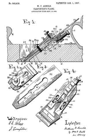
Figure 1 is a longitudinal vertical section of a plane embodying my improvements. Fig. 2 is a perspective view of the top bit. Fig. 3 is a perspective view of the cutting-bit. Fig. 4 is a plerspective view of the shoe.
1 is the stock, aving the throat 2, handle 3, and button 4.
5 is the shoe. Its lower end, or, as it may be termed, its “sole” 6, is flat, with a beveled toe 7 and a shouldered heel 8. Through the sole is made the bit-opening 9. The sides of the sole are bounded by low flanges 10.
In the shank of the shoe is formed a groove 11, which near its upper portion is out through to form a slot 12. In the groove 11 is seated a slide 13, on the upper surface of which is a bit-holding lug 14. This lug may be of any shape, here shown rectangular, and there may be more than one of them, two being here shown. From the under side of the slide projects a lug 15, which plays in the slot 12 of the shoe-shank. The end of said shank is formed with a downwardly-projecting lug 16. An adjusting-screw 17 is seated in lugs 16 and 15, said screw having, as shown in Fig. 1, its outer portion 18, which passes through lug 16, right-hand threaded and its inner portion 19 reduced and left-hand threaded to opperate in lug 15. By this reversal of the threads the screw 17 is enabled to move the slide 13 up or down.
The shoe 5 has a central binding-screw 20, and on each side it has slots 21, in which are fitted holding-screws 22. The shoe 5 is fitted to the stock 1 by passing it up through the throat 2 from below, so that, as seen in Fig. 1, its sole 6 fits up flush with the bottom of the stock, the throat being correspondingly cut away to receive said sole. At this point two improvements are to be noted. The first is that by having the shouldered heel 8 fitting squarely, as seen in Fig. 1, against a substantial thickness of the stock the latter at this point is not, as is usual, cut down to a feather-edge, which is a defect, both in affording a weak bearing and in permitting the entrance of slivers; but with the substantial heel 8, bearing against a good thickness of wood, afirm bearing is obtained against end thrust, and no splinters can enter. The second point is that by having the low side flanges 10 on the sole of the shoe I need cut away but a small portion of the throat-walls to receive them flush.
In the ordinary construction in which the side flanges of the shoe run up high to receive the cross-pin which forms part of the bit-holding devices a great part of the throat-walls has to be cut away to let them in. This weakens the stock across the throat, and many stocks break in falling; but with the low flanges 10 of my construction a minimum of wood is cut away to fit them, and said flanges can be low, because I dispense with the customary cross-pin which they usually carry.
The shoe 5 is adjustably secured to the stock by the holding-screws 22, (seen in Fig. 4,) which are deep-seated in the wood. The binding-screw 20 also enters the wood, as seen in Fig. 1.
23 is the cutting-bit. It is formed with a long slot 24, provided with enlargements 25. The cutting-bit lies upon the shoe 5, its slot 24 fitting over the binding-screw 20 and its enlargements 25 fitting over the holding-lugs 14 of the slide 13.
The top bit shown in Fig. 2 is composed, as usual, of the blank blind bit 26 and the top cap 27. The two are adjustably fitted together by the screws 23, passing through the slots 29. A slot 30 in the top cap and an alined slot 31 in the blind bit, Fig. 1, enable them to be fitted over the binding-screw 20.
The novel feature of the to bit is the slitting of the blind bit 26 to form a spring-tongue 31, Fig. 2. Against this spring-tongue bears a pressure-screw 32, seated in the top cap, which has the function when the top bit is in place, as shown in Fig. 1, of forcing the spring-tongue down upon the cutting-bit, which pressure being resisted by the binding-screw 20 effectually clamps both top bit and cutting-bit to the shoe. By relieving this pressure, as by turning back the pressure-screw 32, the cutting-bit can be properly adjusted through the action of the adjusting-screw 17. The shoe itself can be adjusted as the stock wears, and the top bit can be adjusted on the cutting-bit to determine the shaving.
The advantage of the right and left threaded adjusting-screw 17 is that its threaded bearing in the slide-lug 15 is less liable to friction and to wear and tear resulting in lost motion than if a plain collar-bearing were used, as is customary. It is accurate and easy in its movement.
Another advantage of my invention lies in the connections between the cutting-bit and the adjacent parts which result in freeing said bit of all directly-connected lugs or other attachments which tend to interfere with the work of sharpening it. As I have it there is nothing connected with it and it is left clean to be handled as required.
Having thus described my invention, what I claim as new, and desire to secure by Letters Patent, is —
1. In a carpenter’ s plane, a shoe having its sole formed with a shouldered heel to bear against a corresponding shoulder in the stock-throat.
2. In a carpenter s plane, the combination of a stock, the throat of which at the lower terminus of its rear wall is formed with a bearing-shoulder, and a shoe the sole of which is formed with a shouldered heel bearing against the shoulder of the stock-throat.
3. In a carpenter’s plane, the combination of a shoe secured in the stock-throat, the shank of said shoe having a groove terminating in a slot at its upper end; a slide seated in said shoe-shank groove, and having a lug passing down through said slot said slide having also a holding-lug on its upper surface; a cutting-bit having an opening to engage the holding-lug of the slide; means for clamping the bit to the shoe ; and means engaging the downwardly-extending lug of the slide for adjusting said slide.
4. In a carpenter’s plane, the combination of a shoe secured in the stock-throat, the shank of said shoe having a groove terminating in a slot at its upper end; a slide seated in said shoe-shank groove and having a holding-lug on its upper surface; a cutting-bit having an opening to engage the holding-lug, means for clamping the bit to the shoe; and means for adjusting the bit consisting of a lug on the slide playing down through the shoe-shank slot, a lug on the shoe, and a right and left hand threaded screw seated in said lugs.
5. In a carpenter’s plane, the combination of a shoe secured in the stock-throat, the shank of said shoe having a groove terminating in a slot at its upper end; a slide seated in said shoe-shank groove; a cutting-bit; inter-engaging devices between the bit and slide; means for clamping the bit to the shoe; and means for adjusting the bit consisting of a lug on the slide playing down through the shoe-shank slot, a lug on the shoe, and a right and left hand threaded screw seated in said lugs.
6. In a carpenter’s plane, the combination of a shoe secured in the stock-throat; a cutting-bit adjustably seated on the shoe; a top bit comprising a blank blind bit and a top cap, said blind bit being slit to form a spring-tongue; a pressure-screw in the top cap to force the spring-tongue down upon the cutting-bit; and a binding-screw passing through the top bit, the cutting-bit and the shoe, into the stock, to resist the pressure-screw, whereby the cutting-bit is clamped to the shoe.
7. In a carpenter’s plane, the combination of a shoe secured in the stock-throat; a slide seated in the shoe and having a holding-lug on its face; means for adjusting the slide; a cutting-bit having an opening engaging the holding-lug of the slide; a top bit comprising a blank blind bit and a top cap, said blind bit being slit to form a spring-tongue; a pressure-screw in the top cap to force the spring-tongue down upon the cutting-bit; and a binding-screw passing through the top bit, the cutting-bit and the shoe, into the stock, to resist the pressure-screw, whereby the cutting-bit is clamped to the shoe.
8. In a carpenter’s plane, the combination of a shoe secured in the stock-throat; a slide seated in the shoe and having a holding-lug on its face; means for adjusting the slide consisting of a lug on the slide, a lug on the shoe and a right and left hand threaded screw engaging said lugs; a cutting-bit having an opening engaging the holding-lug of the slide; a top bit comprising a blank blind bit and a top cap, said blind bit having a spring-tongue; a pressure-screw in the top cap to force the spring-tongue down upon the cutting-bit; and a binding-screw passing through the top bit, the cutting-bit and the shoe, into the stock, to resist the ressure-screw, whereby the cutting-bit is clamped to the shoe.
9. In a carpenter’s plane, the combination of a shoe having its solle formed with a shouldered heel and bounded by low side flanges, said sole being iet into corresponding depressions in the stock, a slide seated in the shoe and having a holding-lug on its face; means for adjusting the slide, consisting of a lug on the slide, a lug on the shoe and a right and left hand threaded screw engaging said lugs; a cutting-bit having an opening engaging the holding-lug of the slide; a top bit comprising a blank blind bit and a top cap, said blind bit having a spring-tongue; a pressure-screw in the top cap to force the spring-tongue down upon the cutting-bit; and a binding-screw passing through the top bit, the cutting-bit and the shoe, into the stock, to resist -the pressure-screw, whereby the cutting-bit is clamped to the shoe.
In testimony whereof I have signed my name to this specification in the presence of two subscribing witnesses.
WILLIAM F. ARNOLD.
Witnesses:
CHARLES H. TAYLOR,
N. A. ACKER.