
| PLEASE NOTE: The images presented on this page are of low resolution and, as a result, will not print out very well. If you wish to have higher resolution files then you may purchase them for only $2.95 per patent by using the "Buy Now" button below. All purchases are via PayPal. These files have all been cleaned up and digitally enhanced and are therefore suitable for printing, publication or framing. Each zip package contains all the images below (some packages may contain more), and purchased files can be downloaded immediately. |
UNITED STATES PATENT OFFICE.
_________________
EDWARD S. MARKS, OF AUBURN, NEW YORK, ASSIGNOR TO OHIO TOOL COMPANY, OF AUBURN, NEW YORK, A CORPORATION OF NEW YORK.
PLANE.
_________________
864,010. Specification of Letters Patent. Patented Aug. 20, 1907.
Application filed March 7, 1907. Serial No. 361,029.
_________________
To all whom it may concern:
Be it known that I, EDWARD S. MARKS, a citizen ofthe United States, residing at Auburn, in the county of Cayuga and State of New York, have invented or discovered certain new and useful Improvements in Planes, of which the following is a specification, reference being had therein to the accompanying drawings.
My invention relates to adjustable handles for planes.
The object of my invention is to provide a handle of the character specified which shall be simple in character, which may be easily and quickly adjusted to any desired position, and which will be securely and rigidly held in its adjusted position.
To these ends my invention, in its preferred form, comprises a handle rockingly mounted on a concave seat with which the base of the plane is provided, cooperating devices on the handle and base, which, when in engagement with one another, are adapted to hold the handle against tilting movement, and means for securely locking the handle in a position with said interlocking devices in engagement with one another.
While, as above stated, I prefer to form the handle and its seat on the base of the plane with interlocking devices I consider it to be within the scope of my invention to omit these devices and to hold the handle in its adjusted position by means of the aforesaid locking means alone, or to form these cooperating interlocking devices upon the handle and some part of the body of the plane other than the base thereof.
One construction in which my invention may be embodied is illustrated in the accompanying drawings, in which:–
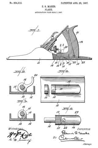
Figure 1 represents a longitudinal section through the handle portion of a plane constructed in accordance with my invention. Figs. 2 and 3 are cross-sectional views taken on the lines 2–2 and 3–3, respectively, Fig. 1. Fig. 4 is a plan view of the base of the plane shown in Fig. 1, with the handle member and clamping device removed. Fig. 5 is a bottom plan view of the handle member shown in Fig. 1.
Like characters indicate like parts throughout the several views of the drawings.
The base 12 of the plane is provided with a concave seat 13, firmly supporting the handle member 14 rockingly seated thereon, and with means for further pivotally supporting said handle member, said means as herein shown comprising a pair of upstanding, perforated lugs 15, 15, formed integral with the base 12. The handle member 14 is provided with a fixed, rigid, forwardly projecting pintle 16, adapted to enter the perforations in the lugs 15, 15, and is preferably formed with a convex under surface to cooperate with the concave seat 13.
As heretofore stated, I prefer to form the handle member and base with cooperating interlocking devices adapted to prevent rocking movement of the handle member when said devices are in engagement with one another, and to this end, in the construction shown, the handle member 14 is provided on its under surface with a plurality of’ grooves or recesses, 17, 17, while the base of the plane, at the junction of the seat 13 with the base of the rearmost lug 15, is provided with a lug 18, adapted to enter any one of the grooves 17, 17, according to the angular position of the handle member 14.
Means are provided for clamping the handle member 14, and for holding the same securely against any movement longitudinally of the plane. This means, in the construction shown, comprises an eccentric locking device 19, rotatably mounted on the pintle 16, between the lugs 15, 15. The locking device 19 is provided with a finger piece 20 by means of which it may be operated, and is adapted, when in its operative position, as shown in Fig. 2, by means of a wedging action between the base 12 and the pintle 16, to force the pintle 16 tightly against the upper sides of the perforations in the lugs, 15, 15, thereby securely holding the handle member against either longitudinal or rotary movement.
As herein shown the handle member 14 comprises a wooden handle 21, to which is permanently attached, as by a suitable screw 22, a metal shoe 23, the pintle 16, and grooves 17, 17 being formed upon said shoe 23. lt will be obvious, however, that the handle member 14, might be made in a single piece from suitable material.
In order to adjust the handle to any desired position, the finger piece 20 is raised from the position shown in Fig. 2, thereby releasing the locking device 19. The handle member 14 is then moved bodily backward until the lug 18 is clear of the groove 17, 17, after which the handle is turned into the desired position with one of the grooves 17, 17, opposite the lug 18. The handle is then moved forward into its original longitudinal position, thereby causing the lug 18 to enter the desired groove 17, and the locking device 19 again moved to locking position.
While I, in order that my invention may be more easily understood, have described the same as embodied in the particular construction shown, I wish it to be distinctly understood that I do not limit myself to this construction, it being obvious that many changes might be made therein without departing from the spirit and scope of my invention.
The concave seat 13 herein shown provides a much firmer support for the handle member than is provided in any construction of which I am aware.
Having thus described my invention I claim and desire to secure by Letters Patent:
1. In a plane, the combination with a concave handle seat, of a handle rockingly mounted thereon for angular movement transverse to the plane, and devices for retaining said handle in adjusted position.
2. In a plane, the combination with a base provided with a concave handle seat, of a handle rockingly mounted on said seat and pivotally connected to said base, and devices for retaining said handle in adjusted position.
3. In a plane, the combination with a handle mounted for angular adjustment and for longitudinal movement, of means for engaging said handle to hold the same against angular movement when in one longitudinal position, and means for locking said handle against longitudinal movement.
4. In a plane, the combination with a base provided with a curved handle seat, a locking lug, and one or more perforated lugs, of a handle member with a curved base to cooperate with said curved seat, a plurality of grooves adapted to cooperate with said locking lug, and with a forwardly projecting pintle entering said perforated lugs, and a clamping device engaging said pintle.
5. In a plane, the combination with a concave handle seat provided with a projecting lug, of a handle provided with a plurality of grooves adapted to receive said lug, and means for holding said handle with said lug in engagement with one of said grooves.
6. In a plane, a rockingly mounted handle, interlocking means on said handle and a fixed part oi the plane for holding said handle against rocking movement, said handle being bodily movable to release said interlocking means.
7. In a plane, the combination with a base provided with a concave handle seat, a locking lug, and one or more perforated lugs, of a handle member provided with a convex base, a plurality of grooves adapted to cooperate with said locking lug, and with a forwardly projecting pintle entering said perforated lugs, and a clamping device engaging said pintle.
8. In a plane, the combination with a plurality of bearing members, of a handle member having a projecting portion adapted to turn in said bearing members, and clamping means engaging said projecting portion beyond one of said bearing members.
In testimony whereof I affix my signature, in presence of two witnesses.
EDWARD S. MARKS.
Witnesses:
JOHN W. BRAINARD,
RALPH R. KEELER.