

| PLEASE NOTE: The images presented on this page are of low resolution and, as a result, will not print out very well. If you wish to have higher resolution files then you may purchase them for only $2.95 per patent by using the "Buy Now" button below. All purchases are via PayPal. These files have all been cleaned up and digitally enhanced and are therefore suitable for printing, publication or framing. Each zip package contains all the images below (some packages may contain more), and purchased files can be downloaded immediately. |
UNITED STATES PATENT OFFICE.
_________________
HARRISON W. LEWIS, OF BATH, NEW YORK.
BEVELING-PLANE.
_________________
Specification of Letters Patent No. 8,655, dated January 13, 1852.
_________________
To all whom it may concern:
Be it known that I, HARRISON W. LEWIS, of Bath, in the county of Steuben and State of New York, have invented a new and useful Improvement in Beveling-Planes; and I do hereby declare that the following is a full and exact description of the same, reference being had to the annexed drawings, making part of this specification, in which —
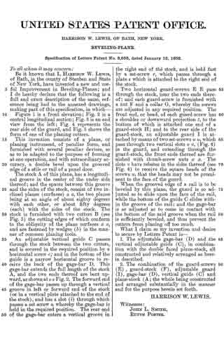
Figure 1 is a front elevation; Fig. 2 is a central longitudinal section; Fig. 3 is an end view from the left; Fig. 4 represents the rear side of the guard, and Fig. 5 shows the form of one of the planing cutters.
This invention consists of a plane, or planing instrument, of peculiar form, and furnished with several peculiar devices, so as to be adapted to the purpose of forming at one operation, and with extraordinary accuracy, a double bevel upon the grooved edge of a stile or rail of a panel door.
The stock A of this plane, has a longitudinal groove in the center of the under side thereof; and the spaces between this groove and the sides of the stock, consist of two inclined planes (surfaces) a a, the two planes being at an angle of about eighty degrees with each other, or about fifty degrees (each) with the sides of the stock. The stock is furnished with two cutters B (see Fig. 5) the cutting edges of which conform to the obliquity of the plane surfaces a a, and are fastened by wedges (b) in the manner of common planing tools.
An adjustable vertical guide C passes through the stock between the two cutters, and is secured in the required position by a horizontal screw c; and in the bottom of the guide is a narrow horizontal groove to receive the back of the gage-bar D. This gage-bar extends the full length of the stock A, and the two ends thereof are bent upward, as shown at e e Fig. 2. The forward end of the gage-bar passes up through a vertical groove in left or forward end of the stock (or in a vertical plate attached to the end of the stock), and has a slot (i) through which passes a set screw a whereby the gage-bar is held in the required position. The rear end of the gage-bar enters a vertical groove in the right end of the stock, and is held fast by a set-screw r, which passes through a plate s which is attached to the right end of the stock.
Two horizontal guard-screws E E pass through the stock, near the two ends thereof; and each guard-screw is furnished with a nut F and a collar G, whereby the screws are adjusted in any required position. The front end, or head, of each guard-screw has a shoulder or downward projection t, to the bottom of which is attached one end of a guard-stock H; and to the rear side of the guard-stock, an adjustable guard I is attached by means of two set-screws u u, which pass through two vertical slots v v, (Fig. 4) in the guard, and extending through the guard-stock, the front ends thereof are furnished with thumb-screw nuts x x. The slots v have rebates in the sides thereof (see Fig. 4) to receive the square heads of the screws u, that the heads may not be prominent to the face of the guard.
When the grooved edge of a rail is to be beveled by this plane, the guard is so adjusted as to slide upon the face of the rail, while the bottom of the guide C slides within the groove of the rail; and the gage-bar is so adjusted as to come in contact with the bottom of the said groove when the rail is sufficiently beveled, and thus prevent the cutters from planing off too much.
What I claim as my invention and desire to secure by Letters Patent is —
1. The adjustable gage-bar (D) and the vertical adjustable guide (C), in combination with the double faced plane-stock, all constructed and relatively arranged as herein described.
2. The combination of the guard-screws (E) , guard-stock (F), adjustable guard (I), gage~bar (D), vertical guide (C) and plane-stock (A; the whole being constructed and arranged substantially in the manner and for the purpose herein set forth.
HARRISON W. LEWIS.
Witnesses:
JOHN L. SMITH,
RUFUS PORTER.