
| PLEASE NOTE: The images presented on this page are of low resolution and, as a result, will not print out very well. If you wish to have higher resolution files then you may purchase them for only $2.95 per patent by using the "Buy Now" button below. All purchases are via PayPal. These files have all been cleaned up and digitally enhanced and are therefore suitable for printing, publication or framing. Each zip package contains all the images below (some packages may contain more), and purchased files can be downloaded immediately. |
UNITED STATES PATENT OFFICE.
_________________
JOHN V. PETRUSICH, OF CHICAGO, ILLINOIS.
EXTENSION-PLANE.
_________________
869,016. Specification of Letters Patent. Patented Oct. 22, 1907.
Application filed June 17, 1907. Serial No. 379,311.
_________________
To all whom it may concern:
Be it known that I, JOHN V. PETRUSICH, a citizen of the United States, residing at Chicago, in the county of Cook and State of Illinois, have invented a new and useful Extension-Plane, of which the following is a specification.
This invention relates to improvements in planes.
It is well known that carpenters and others using this class of tool find occasion to use several sizes of the same and the object of this invention is to provide what may be termed an extension plane or a plane in which the several essential sizes of the tool are combined in one.
With this and other objects in view the invention consists in the construction and combination of parts to be hereinafter described, pointed out and claimed in the following specification and illustrated in the accompanying drawings, in which:–
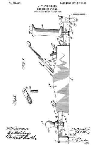
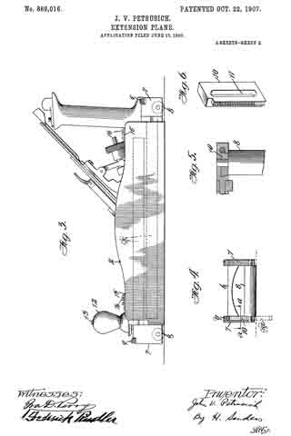
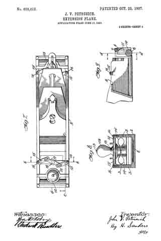
Figure 1 is a side elevation of the device complete. Fig. 2 is a detail of a slotted bar and pin therefor used for locking the extension members. Fig. 3 is a view similar to Fig. 1 showing in dotted lines the position of the extension members when the plane is closed. Fig. 4 is an end of the device partly in section and taken on line d–d Fig. 9. Fig. 5 is a view in section of Fig. 4 taken on line a–a. Fig. 6 is a detail perspective of the rack employed in the extension portion of the device. Fig. 7 is a plan view of the plane closed. Fig. 8 is a front view of Fig. 7, partly in section, and taken on the line b–b. Fig. 9 is a section taken on line c–c of Fig. 7.
Like reference characters indicate corresponding parts throughout the several views.
The reference numeral 2 represents a plane of ordinary or preferred construction having longitudinal sockets 2a opening in either extremity of the side walls 2b of the plane and running horizontally and parallel with each other as shown in Fig. 3.
The numeral 3 represents extension rods adapted to fit slidably into the sockets 2a and having graduations 4 on their lateral surfaces for measuring off the work. Roller-carriers 7 are provided at the external extremities of the extension rods as shown in section in Fig. 4 and as shown complete in Fig. 1, in which are pivoted the rollers 8 for the purpose of carrying the plane smoothly over the work. A brace 6 connects either pair of roller-carriers as shown in Fig. 7 for the purpose of holding the extension rods rigidly parallel.
Either roller-carrier arranged on either left-hand extension rod is recessed on the surface adjacent the roller so that it may carry a rack 10 provided with a slot 11 which engages the pivot of the roller 8. Each left-hand roller-carrier is fiuther provided with a worm 9 which engages the rack 10 for the purpose of raising and lowering the same as shown in detail in Figs. 4 and 5. When the rack 10 is dropped below the lelt-hand edge of the work it serves as a lateral drop guide to keep the plane flush with that edge of the work as shown in Fig. 1.
12 represents a knob of the plane provided with a screw 13 running the entire length of the same and protruding beyond the lower extremity thereof.
14 represents the upper section of a clamp slidably arranged on the extension rods and provided with a threaded aperture to receive the screw 13 protruding from the knob 12 which is seated on said portion of the clamp.
14a is the lower section of the clamp arranged on the extension rods in a manner similar to the upper portion and provided with a threaded aperture to receive the screw 13 that extends through the upper portion of the clamp. By turning the knob 12 to the right the sections of the clamp 14 and 14a are drawn together and are caused to grip the extension rods firmly thus affording rigid handles to the plane.
15–15 represents a pair of slotted bars arranged on the side walls of the plane by means of the screws 16 movable with said bars. The screws 16 extend vertically through the side walls of the plane to the sockets 2a and when the slotted bars are turned at right angles with the side walls of the plane the screws 16 engage the extension rods resting within the said sockets and hold them firmly.
17 represents a horizontal connecting link pivoted at 18 and engaging the slotted bars 15 in the manner shown in Fig. 7. By turning this horizontal link until it lies in a straight angle with the two slotted bars it will cause the screws 16 to engage the extension rods as above described. Thus it will be seen, the extension rods can be partly withdrawn from their sockets and locked in that position.
Either end of the plane is provided with similar extension apparatus and hence a description of that on one end is a description of the apparatus on the other.
Having fully described my invention, what I wish to claim and secure by Letters Patent of the United States is:
1. In a plane, extension means journaled in the side walls thereof, a sliding clamp mounted on said extension means, a knob seated on said sliding clamp and supporting means terminally carried by said extension means substantially as described.
2. In a plane, extension means journaled in the side walls thereof, an extension stop carried on the side walls thereof, a sliding clamp mounted on said extension means, a knob seated on said sliding clamp, roller-carriers terminally arranged on said extension means, a roller pivoted within said roller-carriers and a lateral drop guide carried by said roller-carrier substantially as described.
3. In Combination with a plane having longitudinal sockets in the side walls thereof, sliding extension rods arranged therein, a. sliding screw-actuated clamp arranged on said extension rods, a knob seated on said clamp by which the same may be anchored or released, roller-carriers terminally carried by said extension rods, a roller pivotally carried by said roller carriers, a brace 6 connecting said roller-carriers and a worm and rack carried by said roller-carriers substantially as described.
In testimony that I claim the foregoing as my own, I have hereto affixed my signature in the presence of two witnesses.
JOHN V. PETRUSICH.
Witnesses:
ROSE GREENBERG,
FREDERICK RINDLER.