| PLEASE NOTE: The images presented on this page are of low resolution and, as a result, will not print out very well. If you wish to have higher resolution files then you may purchase them for only $2.95 per patent by using the "Buy Now" button below. All purchases are via PayPal. These files have all been cleaned up and digitally enhanced and are therefore suitable for printing, publication or framing. Each zip package contains all the images below (some packages may contain more), and purchased files can be downloaded immediately. |
UNITED STATES PATENT OFFICE.
_________________
JOHN H. SHAW, OF NEW HAVEN, CONNECTICUT, ASSIGNOR TO SARGENT & COMPANY, OF NEW HAVEN, CONNECTICUT, A CORPORATION OF CONNECTICUT.
PLANE.
_________________
869,267. Specification of Letters Patent. Patented Oct. 29, 1907.
Application filed August 10, 1905. Serial No. 273,590.
_________________
To all whom it may concern:
Be it known that I, JOHN H. SHAW, of the city and county of New Haven, State of Connecticut, have invented new and useful Improvements in Planes, of which the following is a full, clear, and exact description, when taken in connection with the accompanying drawings, which form a part thereof, and in which —
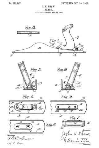
Figure 1 represents a side elevation of a plane embodying the invention, Fig. 2 an end view of the same, Fig. 3 a similar view with the handle shown adjusted to a different position, Fig. 4 a top view of the handle end of the plane, Fig. 5 a similar view with the handle removed, Fig. 6 a similar view with the supporting block removed, Fig. 7 a bottom view of the handle plate, and Fig. 8 a side elevation of the supporting block.
In all figures, similar letters of reference represent like parts.
This invention relates to planes, and has for its object the production of a simple and efiicient construction by which the handle may be adjusted so that the plane can be used close to a wall or other object without injury to the hand of the operator.
When a plane is used in proximity to an object, as a wall, it is diflicult to bring the plane close to the corner without interfering with the hand of the operator. To this end various methods have been devised by which the handle may be adjusted or turned to an angle other than a right angle to the bottom of the plane so as to remove the hand of the operator further from the side of the plane against the wall.
The present invention consists of a removable supporting block for the handle, which may be mounted on the ordinary plane body so that the handle may be adjusted or rotated on the supporting block to project at the desired angle, together with other improvements and combinations of parts hereinafter described and claimed.
For a better understanding of the invention reference is had to the accompanying drawings, in which the parts designated by the letter A represent the plane body and B the sides thereof. On the plane body, near the rear, is a usual base C for the handle, having a screw hole or holes D. When a handle is mounted on this base it assumes the ordinary position at right angles to the plane body, and is incapable of adjustment.
A supporting block E is therefore provided, which is herein shown fiat on its under side and convex transversely on its upper face (Figs. 2 and 3). The supporting block E is adapted to be secured to the plane body by a screw F, or other means, taking into one of the screw holes D.
The handle G is provided at its lower end with a plate H concaved transversely as shown, so that its under face is adapted to fit on the convex surface of the supporting block E. The plate is provided with one or more transverse slots K for the reception of screws L, which extend through the slots and take into screw holes M in the block E. The heads of the screws L or washers N, engaged thereby, bear on the plate H to bind in its adjusted position.
To shift the handle from one angle with the plane body to another it is only necessary to unscrew the screws L and the plate H will then be capable of sliding in either direction on the block E, so that the handle will assume either of the positions indicated in Figs. 2 or 3. When the screws L are tightened the handle is secured to its adjusted position. As the block E is removable the plane body may be used with an adjustable handle or with an ordinary handle as desired.
Having now described my invention, what I claim and desire to secure by Letters Patent is:
In a plane, the combination with the plane body; of a removable supporting block curved in cross section and adapted to be rigidly secured to the plane body; a correspondingly curved plate adapted to fit on said supporting block; a handle secured to said plate; slots in said plate; and screws projecting through said slots and engaging said block to hold said plate and handle in their adjusted position, substantially as described.
In witness whereof, I have hereunto set my hand on the 4th day of August, 1905.
JOHN H. SHAW.
Witnesses:
W. A. RICE,
L. F. BREESE.


