
| PLEASE NOTE: The images presented on this page are of low resolution and, as a result, will not print out very well. If you wish to have higher resolution files then you may purchase them for only $2.95 per patent by using the "Buy Now" button below. All purchases are via PayPal. These files have all been cleaned up and digitally enhanced and are therefore suitable for printing, publication or framing. Each zip package contains all the images below (some packages may contain more), and purchased files can be downloaded immediately. |
UNITED STATES PATENT OFFICE.
_________________
WILLIAM ERDMANN, OF MADISON, WISCONSIN.
SCRAPER.
_________________
876,789. Specification of Letters Patent. Patented Jan. 14, 1908.
Application filed August 28, 1907. Serial No. 390,520.
_________________
To all whom it may concern:
Be it known that I, WILLIAM ERDMANN, residing at Madison, in the county of Dane and State of Wisconsin, have invented a new and Improved Scraper, of which the following is a specification.
My invention relates to certain new and useful improvernents in scrapers for dressing floors and the like, and the invention primarily has for its object to provide a scraper of an improved construction which can be easily and cheaply manufactured and which will readily and effectively serve its intended purposes. In my invention means are provided for holding and clamping the scraping blade, which means can be easily and quickly adjusted to permit insertion or withdrawal of the blade, as the case may be.
Another object of my invention is to provide a scraper having a yielding pad against which the blade rests to absorb or prevent vibration when the implement is in use.
The invention also embodies certain novel construction, combination and arrangement of parts, all of which will be first described in detail and then be specifically pointed out in the appended claims, reference being had to the accompanying drawings, in which, —
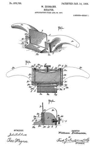
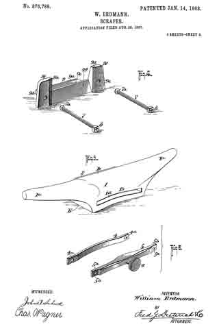
Figure 1, is a perspective view of my invention. Fig. 2, is a central, vertical section thereof. Fig. 3, is a horizontal section on the line 3–3 of Fig. 2. Fig. 4, is a perspective view of the metallic gage and blade holding clamp member. Fig. 5, is a similar view of the stock and handle member. Fig. 6, is a perspective view of the bridge members.
Referring now to the accompanying drawings in which like letters and numerals of reference indicate like parts in all of the figures, 1 designates the stock with which the handles 1a merge, and the stock 1 has its under face plane, while its front face 1c is in a plane held at an obtuse angle to the plane containing the horizontal surfaces 1b of the stock.
Cemented or otherwise held in contact with the front face 1c of the stock 1, is a pad 2, of leather or other similar yielding material of substantially even thickness throughout, and against which the scraping blade 3 is held.
The blade 3 may be of the ordinary type and have the usual cutting edge 3a, as shown.
On the rear the stock 1 is formed with an elongated countersunk portion 1d to receive the bow shaped bridge member 4 and the set screw carrying bridge bar 5, the bar 5 having a threaded aperture to receive the set screw 6 and having its ends cut away as at 5b to form nut holding sockets.
The ends of the bars 4 and 5 have alining apertures 4a and 5a which register with the bolt holes 1x in the stock 1, to permit passage of the clamping bolts 7 which cooperate with the nuts 8, as shown.
9 designates the combined gage and blade holding clamp member which has the usual body 9a whose under face 9b lies in the same plane with that containing the face 1b of the stock 1. The body 9a has an upwardly projecting rear face 9c held at an acute angle to the face 9b and it also has upwardly projecting arms 9c having depressed blade receiving portions 9d and bolt apertures 9e together with a clearance space 9f to permit passage for the shavings.
In practice, the parts are arranged as shown in Figs. 1, 2 and 3. To loosen the member 9 and release the blade, it is only necessary to turn the set screw to ease up on the tension exerted on the bolt, when the blade may be easily withdrawn for sharpening or otherwise. When it is desired to reinsert the blade it is only necessary to replace the same in the position shown in Fig. 1, within the recesses 9d and tighten up on the set screw, thus exerting a tension on the bolts and drawing the member 9 against the blade, and tightly clamping the blade against the yieldable cushion or pad.
By constructing a scraper as shown and described, the same can be easily and cheaply manufactured at a minimum expense and the blade can be readily adjusted to its proper position as well as easily and quickly removed for sharpening, the provision of the yieldable pads serving to take up any vibrations which may occur during the operation of the implement and prevent chattering of the blade.
It will be noticed that the cut away ends of the set screw carrying bridge member 5 together with the countersunk portion of the stock 1 in which the bridge members are held, serve as a nut lock and prevent the nuts becoming loose, it being understood that the heads 7a of the bolts have their faces held at a slight angle to the longitudinal axis of the bolts, thus preventing turning of the bolt when the set screw is tightened up.
From the foregoing description, taken in connection with the accompanying drawings, it is thought the complete construction, opoperation and numerous advantages of my invention will be readily understood by those skilled in the art to which the invention appertains.
What I claim is, —
1. The combination with the stock, the blade holding clamp member, and means for mounting the blade holding clamp member on the stock, of means carried by the stock and cooperatively connected with the aforesaid mounting means for causing the blade carrying clamp member to clamp the blade against the stock substantially as shown and described.
2. The combination with the stock, the blade holding clamp member having blade receiving recesses and the blade therein, of securing means passed through the clamping member and the stock for holding the clamping member to the stock, and means for tightening up or loosening said securing means to clamp or release the blade, substantially as shown and described.
3. The combination with the stock, the blade holding clamp member having blade receiving recesses and the blade therein, of securing means passed through the clamping member and the stock for holding the clamping member to the stock, means for tightening up or loosening said securing means to clamp or release the blade, said last named means comprising a pair of bridge members carried by the stock and cooperatively connected with the securing means, and means carried by one of said bridge members for exerting a tension on said securing means to draw the blade holding clamp member tightly against the blade, substantially as shown and described.
4. The combination with the stock, the blade holding clamp member having blade receiving recesses and the blade therein, of securing means passed through the clamping member and the stock for holding the clamping member to the stock, means for tightening up or loosening said securing means to clamp or release the blade, said last named means comprising a pair of bridge members carried by the stock and cooperatively connected with the securing means, means carried by one of said bridge members for exerting a tension on said securing means to draw the blade holding clamp member tightly against the blade, and a yieldable pad interposed between the blade and the blade holding clamp member and the stock, substantially as shown and described.
5. The combination with the stock, the blade holding clamp member and the blade, and bolts for securing the blade holding member to the stock, of tension devices for said bolts to cooperate with the blade holding clamp members, substantially as shown and described.
6. The combination with the stock, the blade holding clamp member and the blade, and bolts for securing the blade holding member to the stock, of tension devices for said bolts to cooperate with the blade holding clamp members, said tension devices comprising a bridge member connected with said bolts, and means cooperating with the bridge member for exerting a tension on said bolts.
7. The combination with the stock, the blade holding clamp member and the blade, and bolts for securing the blade holding member to the stock, of tension devices for said bolts to cooperate with the blade holding clamp members, said tension devices comprising a bridge member connected with said bolts, means cooperating with the bridge member for exerting a tension on said bolts, said last named means comprising a set screw passing through said bridge member, substantially as shown and described.
8. The combination with the stock, the blade holding clamp member and the blade, and bolts for securing the blade holding member to the stock, of tension devices for said bolts to cooperate with the blade holding members, said tension devices comprising a bridge member connected with said bolts, means cooperating with the bridge member for exerting a tension on said bolts, said last named means comprising a set screw passing through said bridge member, and a supplemental bridge member held within said stock and adapted to be cooperatively engaged by said set screw, substantially as shown and described.
WILLIAM ERDMANN.
Witnesses:
ERNST SAABER,
REINHOLD MATHWIG.