| PLEASE NOTE: The images presented on this page are of low resolution and, as a result, will not print out very well. If you wish to have higher resolution files then you may purchase them for only $2.95 per patent by using the "Buy Now" button below. All purchases are via PayPal. These files have all been cleaned up and digitally enhanced and are therefore suitable for printing, publication or framing. Each zip package contains all the images below (some packages may contain more), and purchased files can be downloaded immediately. |
UNITED STATES PATENT OFFICE.
_________________
BIRDSILL HOLLY, OF SENECA FALLS, NEW YORK.
HAND-PLANE.
_________________
Specification of Letters Patent No. 9,094, dated July 6, 1852.
_________________
To all whom it may concern:
Be it known that I, BIRDSILL HOLLY, of Seneca Falls, in the county of Seneca and State of New York, have invented certain new and useful Improvements in Metal Bench-Planes; and I do hereby declare that the following is a full, clear, and exact description of the same, reference being had to the accompanying drawings, forming part of this specification, in which —
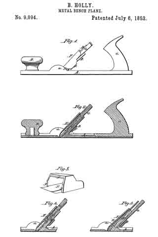
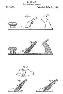
Figure 1, is a side view of a cast iron bench plane with my improvements. Fig.
2, is a longitudinal section of the same. Fig.
3, is a perspective view of the cap. Figs. 4 and 5 are sections of parts of the plane showing the iron, wedge and cap in different positions.
Similar letters of reference indicate corresponding parts in each of the several parts.
The nature of this invention consists, 1st, in certain improvements in the stock and in the cap of the iron which allow the width of the throat to be altered for different kinds of work; 2nd, in certain means by which the cap of the iron is always caused to drop into its place without requiring any adjustment or setting.
To enable those skilled in the art to make and use my invention I will proceed to describe fully its construction and operation.
A, is the stock which consists of a cast iron plate with the stem B, standing up from it at a suitable inclination, and with two projecting pieces, a a, one on each side close in front of the stem. The stem B, is of about the same width as the plane iron and is made of tapering thickness, being rather smaller at the top. The two projecting pieces a a, are of nearly semicircular form and are of such width or thickness, or are at such a distance apart as to allow the plane iron and cap to slide freely between them. The stock is furnished at the back part with a handle C, similar to a common plane handle, and in front of the throat with a knob D.
The plane iron E, is similar in its general character to the iron of a common plane. The cap F, consists of a cast iron plate similar in form to the cap of a common plane iron, but it has a loop f, which is of sufficient width and depth to lit over the plane iron, the stem B, and the wedge G, by which the iron is secured. The bottom parts of the sides of the loop at g, g, form shoulders fitting to the semicircular projecting pieces a, a, of the stock and are at such a distance from the lower edge of the cap that when they rest on the projections the edge of the cap will be just above or within the face of the plane and parallel transversely to it; the edge of the cap is chilled or hardened.
The plane iron E, is placed between the cap F, and the stem B, and the wedge may be inserted between the iron and the stem as shown in Figs. 1 and 2; between the cap and the iron as shown in Fig. 4; or between the back of the stem and the loop f, of the cap as shown in Fig. 5. The first arrangement gives a wide throat which is best for rough work; the second gives a very small throat suitable for planing hard wood or cross grained stud, or for finishing fine work; and the third gives a width of throat about half way between the widths given by the other two arrangements. The difference in the width of the throats is produced by the alteration of the inclination of the iron and cap.
The advantage of having the cap to drop at once with certainty to its place, will be admitted by all accustomed to the use of bench planes, as it dispenses with the necessity of measuring and setting required in the common arrangement; and the want of a simple and sure means of regulating the width of the throat is well known.
What I claim as my invention and desire to secure by Letters Patent, is
1. The loop f on the cap F, in combination with the plane iron E, and the stem B, of the stock in the manner substantially as described, to wit, the said loop fitting over or embracing the plane iron and stem and, allowing the iron to be secured between the cap and the stem by means of a wedge G, placed either between the back of the iron and front of the stem, between the front of the iron and the cap, or between the back side of the stem and back part of the loop, the three positions of the wedge forming three different widths of throat as herein explained.
2. Providing the cap F, with shoulders g, g, which when the cap is placed in the stock of the plane will fall on suitable resting pieces provided in or upon the stock substantially as described.
BIRDSILL HOLLY.
Witnesses:
CHAS. J. MCKEE,
PHILO COWING.


