
| PLEASE NOTE: The images presented on this page are of low resolution and, as a result, will not print out very well. If you wish to have higher resolution files then you may purchase them for only $2.95 per patent by using the "Buy Now" button below. All purchases are via PayPal. These files have all been cleaned up and digitally enhanced and are therefore suitable for printing, publication or framing. Each zip package contains all the images below (some packages may contain more), and purchased files can be downloaded immediately. |
UNITED STATES PATENT OFFICE.
_________________
CHARLES B. STANLEY, OF NEW BRITAIN, CONNECTICUT, ASSIGNOR TO THE STANLEY RULE
& LEVEL COMPANY, OF MERIDEN, CONNECTICUT, A CORPORATION OF CONNECTICUT.
TOOL-HANDLE.
_________________
928,227. Specification of Letters Patent. Patented July 13, 1909.
Application filed February 20, 1909. Serial No. 479,081.
_________________
To all whom it may concern:
Be it known that I, CHARLES B. STANLEY, a citizen of the United States, residing at New Britain, county of Hartford, State of Connecticut, have invented certain new and useful Improvements in Tool-Handles, of which the following is a full, clear, and exact description.
My invention relates to new improvements in tool handles and is particularly useful for plane handles.
The object of the invention is to provide an improved combination of parts whereby composition and similar handles may be constructed in such a way as to effectively withstand the strain which comes upon the fastening screw at the forward portion of the handle, thereby removing the danger of breakage, which has been found to be in this class of handles, very great.
In the manufacture of what are known as imitation rubber handles, the composition material employed is of a fibrous or brittle nature, and it frequently happens, owing to the shape of the handle, that the material through which the forward screw passes is unequal to the strain and that portion of the handle becomes broken.
With my invention I propose to overcome this defect and to provide the handle at its most vulnerable point with an effective reinforcing device which can be very economically produced, and in combination with the remainder of the handle, be used to great advantage.
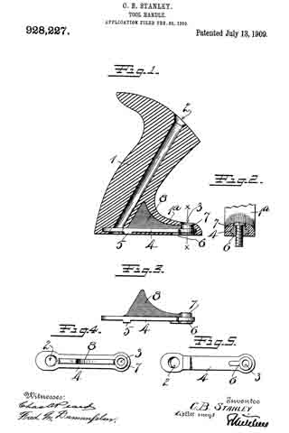
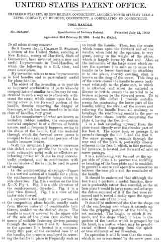
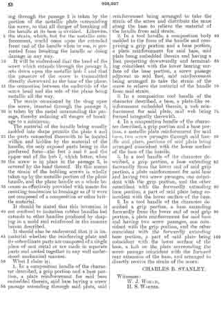
In the accompanying drawings, — Figure 1 is a vertical section of a handle for a plane, the reinforcement therefor being shown in side elevation. Fig. 2 is a section on the line X–X Fig. 1. Fig. 3 is a side elevation of the reinforcement, detached. Fig. 4 is a plan view thereof. Fig. 5 is a view of the under side thereof.
1 represents the body or grip portion of the composition plane handle, usually made from fibrous material of considerable brittleness, molded to the desired shape. The handle is usually screwed to the upper side of the sole of the plane (not shown) by means of suitable fastening devices passing through the apertures 2 and 3. Inasmuch as the aperture 3 is located in a comparatively thin part of the extended base 1a of the handle, the pressure employed in screwing the handle in place is frequently such as to break the handle. Then, too, the strain which comes upon the forward end of the handle, when held by the operator, is very great, owing to the weight of the plane, which is largely borne by that end. Also, the inclination of the large screw which enters the aperture 2 is such as to cause the handle to be forced backward in attaching it to the plane, thereby creating what is known as the drag of the screw. This drag of the screw causes the handle to move backward relatively to the plane sole, to which it is attached, and when the material is fibrous or brittle, causes the material to be broken adjacent to the forward screw. To overcome this defect I provide metallic means for reinforcing the lower part of the handle, taking the strain of the screws and relieving the handle from all tendency to breakage, the reinforcing means in the particular form shown herein comprising the plate 4, having the feet 5–6.
7 is a hub extending upward from the plate 4 and directly over the circular part of the foot 6. The screw hole, or passage 3, extends through the hub 7 and the foot 6. The screw passage 2, extends through the rear end of the plate 4, preferably closely adjacent to the foot 5, which, in this particular instance, is located just forward of said screw passage.
8 is a reinforcing web formed on the upper side of plate A to prevent the buckling or breaking of the base plate and to establish in general a secure and operative connection between the base plate and the remainder of the handle.
It should be understood that although the feet 5 and 6 perform a useful function, their use is preferable rather than essential, as the base plate 4 would in large measure discharge the duties required of it if the feet were removed and it rested directly upon the upper side of the sole of the plane.
It should be understood also that the shape of the reinforcing web where it extends up into the gripping portion of the handle, is not material. The height to which it extends, and the shape which it takes in the portion of the handle which is grasped by the hand, is a matter which may be greatly varied without departing from the spirit or true character of my invention.
In operation it will be seen that the strain which in use is occasioned by the screw passing through the passage 2, is taken by the portion of the metallic plate surrounding the screw, so that all danger of breaking off the handle at its base is avoided. Likewise, the strain, which, but for the metallic reinforcement, would come upon the extended front end of the handle when in use, is prevented from breaking the handle or doing damage in any way.
It will be understood that the head of the screw which extends through the passage 3, sets down upon the metallic hub 7 and that the pressure of the screw is transinitted directly downward to the base of the plane, the connection between the underside of the screw head and the sole of the plane being metallic all the way.
The strain occasioned by the drag upon the screw, inserted through the passage is taken by the metal surrounding the passage, thereby reducing all danger of breakage to a minimum.
The material of the handle being usually molded into shape permits the plate 4 and the parts connected therewith to be located within and hidden by the material of the handle, the only exposed parts being in the preferred form — the feet 5 and 6 and the upper end of the hub 7, which latter, when the screw is in place in the passage 3, is covered by the head thereof. By this means the strain of the holding screws is wholly taken up by the metallic portion of the plane handle, and the plane handle as a whole becomes as effectively provided with means for resisting tendencies to breakage as if it were not composed of a composition or other brittle material.
It should be stated that this invention is not confined to imitation rubber handles but extends to other handles produced by shaping in a mold and reinforced in the manner herein described.
It should also be understood that it is immaterial whether the reinforcing plate and its subordinate parts are composed of a single piece of cast metal or are made in separate parts and united together in any well understood mechanical manner.
What I claim is:
1. In a composition handle of the character described, a grip portion and a base portion, a plate reinforcement for said base embedded therein, said base having a screw passage extending through said plate, said reinforcement being arranged to take the strain of the screw and distribute the same along the base to relieve the material of the handle from said strain.
2. In a tool handle, a composition body molded to the form of the handle and comprising a grip portion and a base portion, a plate reinforcement for said base, said plate being embedded therein and having a foot projecting downwardly and terminating coincident with the lower bearing surface of the base portion, a screw passage adjacent to said foot, said reinforcement being arranged to take the strain of the screw to relieve the material of the handle from said strain.
3. In a composition tool handle of the character described, a base, a plate-like reinforcement embedded therein, a web reinforcement for said plate, said web being formed integrally therewith.
4. In a composition handle of the character described, a grip portion and a base portion, a metallic plate reinforcement for said base, two screw passages through said handle and plate, portions of said plate being arranged coincident with the lower surface of the base of the handle.
5. In a tool handle of the character described, a grip portion, a base extending forwardly from the lower end of said grip portion, a plate reinforcement for said base and having two screw passages, one coincident with the grip portion, and the other coincident with the forwardly extending base portion, a part of said plate being coincident with the lower surface of the base.
6. In a tool handle of the character described a grip portion, a base extending forwardly from the lower end of said grip portion, a plate reinforcement for said base and having two screw passages, one coincident with the grip portion, and the other coincident with the forwardly extending base portion, a part of said plate being coincident with the lower surface of the base, a hub on the plate surrounding the screw passage coincident with the forward rear extension of the base and arranged to directly receive the strain of the screw.
CHARLES B. STANLEY.
Witnesses:
W. J. WORAM,
H. S. WALTER.