| PLEASE NOTE: The images presented on this page are of low resolution and, as a result, will not print out very well. If you wish to have higher resolution files then you may purchase them for only $2.95 per patent by using the "Buy Now" button below. All purchases are via PayPal. These files have all been cleaned up and digitally enhanced and are therefore suitable for printing, publication or framing. Each zip package contains all the images below (some packages may contain more), and purchased files can be downloaded immediately. |
UNITED STATES PATENT OFFICE.
_________________
JAMES HORACE BROWN, OF BOSTON, MASSACHUSETTS.
WOODWORKER’S PLANE.
_________________
936,085. Specification of Letters Patent. Patented Oct. 5, 1909.
Application filed November 17, 1908. Serial No. 462,996.
_________________
To all whom it may concern:
Be it known that I, JAMES HORACE BROWN, a citizen of the United States, and a resident of Mattapan, Boston, in the county of Suffolk and State of Massachusetts, have invented a new and Improved Woodworker’s Plane, of which the following is a full, clear, and exact description.
The purpose of this invention is to provide novel details of construction for a plane, that facilitates the exact adjustment of the cutter bit laterally and longitudinally in the throat of the plane stock, enable the quick and exact graduation for size of the throat opening in said stock, provide novel means for clamping the cutter bit when adjusted in the throat opening.
The invention consists in the novel construction and combination of parts, as is hereinafter described and defined in the subjoined claims.
Reference is to be had to the accompanying drawings forming a part of this specification, in which similar characters of reference indicate corresponding parts in all the views.
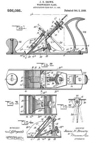
Figure 1 is a partly sectional side view of the improved plane, substantially on the line 1–1 in Fig. 2; Fig. 2 is a partly sectional plan view, substantially on the line 2–2 in Fig. 1; Fig. 3 is a fragmentary plan view, partly in section on the line 3–3 in Fig. 1; Fig. 11 is a sectional side view of details shown in Fig. 1, but showing a changed adjustment thereof and Fig. 5 is a partly sectional view of parts, taken substantially on the line 5–5 in Fig. 1.
The stock for the plane is cast into form from metal, and essentially consists of a flat base plate 10 having vertical walls 10a formed along its side edges, and said side walls having their greater height near their longitudinal centers are curved on their upper edges, as shown for one side wall in Figs. 1 and 4. At a suitable distance from the front end of the stock 10, a transverse throat opening a is formed in the base portion thereof, and at the front and rear edges of said throat, oppositely inclined defining walls a1, a2 are formed on said base portion, as is clearly shown in Fig. 1. Rearward of the throat opening a and parallel therewith, a post 11 is erected on the base 10, said post extending from one side wall 10a to the opposite one, as shown in Figs. 1 and 3, and being located near the longitudinal center of the plane stock.
Novel means is employed for graduating the width of the slot opening a, consisting in the provision of a wedge-shaped tongue piece 12, seated upon the inclined rear defining wall a2 of the slot a, said tongue piece extending across the stock into loose engagement with the inner surfaces of the side walls 10a. The tongue piece 12 is provided with a rearward extension 12a in the form of a flat plate, having at its end a fork 12 projecting from its lower face and adjacent to said fork a cross slot b. The post 11 is thickened near its junction with the base 10, and in said thickened portion a threaded perforation is formed, in which the threaded body of an adjusting said screw screw 13 is screwed, said screw having a roughened head 13a formed or secured on the rear end thereof. The screw 13 extends between the members of the fork 12b and is provided at its end with a collar 13b which projects into the slot b, so that by manipulating the screw the tongue piece 12 can be adjusted to increase or decrease the width of the slot a. The connection between the tongue and screw, permits the tongue to be readily detached from the screw and removed when desired.
The cutter bit 14 of the plane, is in the form of a flat metal plate, preferably formed of steel and having one end beveled to produce a transverse cutting edge c thereon. At the transverse center, a longitudinal slot d is formed in the cutter bit 14 extending of a suitable length between the ends thereof. The cutter bit 14 is seated upon the tongue piece 12 and the upper end of the post 11, said end being sloped forward and downward, as shown in Fig. 1, to adapt it for a proper support of the bit. The bit 14 is held seated upon the tongue piece 12 and post 11 by a novel clamping device that also serves the purpose of a cap plate for the cutter bit, said device comprising the following details: A resilient thin metal plate 15 having a proper length, and a width that is equal with that of the cutter bit, is secured by one end that is uppermost in service upon a spacing block 16 whereon a resilient hook plate 17 is also secured. The spacing block 16 is a flat rectangularly-edged slab of metal from the rear end of which projects a flange 16a at a right angle, said block having parallel sides. The hook is of an equal width with the resilient cap plate 15, and these plates at their upper ends are oppositely lapped upon the upper and lower surfaces of the spacing block 16, whereon they are secured by a rivet or screw, as shown at e. Upon the lower or forward end of the plate 17, a transverse hook g is formed, that is adapted for a hooked engagement with a keeper bar 18 that extends across the stock of the plane above and in contact with the cap plate 15, and is secured by its ends in the side walls 10a of said stock. It will be seen that the hooked engagement of the plate 17 with the keeper bar 18, will hold the cap plate 15 imposed upon the cutter bit 14; and to enforce said engagement set screws h are inserted in the cap plate and spacing block 16, that will graduate the pressure of the cap plate in accord with the degree of projection given the set screws, that bear on said cutter bit near each side edge thereof, as shown in Figs 1, 2 and 4.
In the post 11, near its upper edge, a screw 19 is secured by one end thereof, and thence extends rearward and upward. Upon the threaded body of the screw 19, a sleeve nut i1 is loosely mounted, said nut having a radial flange i formed thereon, and upon a portion of the cylindrical body of said nut, a thread is cut. Upon the threaded body of the nut i1, a nut i2 having a body similar to the flange i is adjustably mounted and adapted for rotatable movement toward or from the flange i. Near the upper end of the cutter bit 14, a transverse slot d1 is formed that crosses the longitudinal slot d. Below the slot d, the adjusting screw 19 is positioned and in such close relation to the cutter bit 14 that the radial flange i1 and the nut i2 will project into the transverse slot a1 and by lateral adjustment may be caused to have lateral contact with the side edges of said slot.
It will be seen that by a screwed adjustment of the nuts i, i2, on the body of the adjusting screw 19, there may be an exact longitudinal adjustment given to the cutter bit let for its projection or retraction in the transverse throat slot a; further, by screwing the flange i1 and nut i2 into an engagement with the defining sides of the cross slot d1, the cutter bit 14 will be firmly held at a desired point of longitudinal adjustment thereof.
Upon the adjusting screw 19, near the post 11, a lever 20 is mounted and secured near one end thereof, a toe m extending from the upper end of said lever through the slot d, having a loose engagement with the defining side edges thereof, the main portion of said lever projecting down near to the base 10, and it will be noted that a side movement of the lever will slightly rock the cutter bit 14 accordingly and thus depress a respective corner of the cutting edge of the bit, enabling an exact adjustment of said edge to adapt it to have a true bearing on the material over which the plane is moved in planing it.
At the front end, a knob 21 is secured that projects vertically from the plane stock, this being a common provision to enable hand pressure to be applied upon the front end of the plane.
The handle 22 of the plane, is provided with a forwardly-projecting flange n at the lower end thereof, said flange having a notch o in the front edge, which receives a stud o1 formed on the rear portion of the base of the stock at its transverse center. The body of the handle 22, is preferably given skeleton form, that affords a flat bottom wall n1 thereon, which is centrally perforated and registers with a threaded perforation formed at the transverse center of the base portion 10; and it will be seen that if the stud o1 is placed in the notch o and a screw p is inserted through the perforation in the handle down into the threaded perforation in the base 10, the handle 22 will be firmly but detachably secured upon the plane stock.
It will be apparent from the foregoing description, that the cutter bit 14 may be given different degrees of inclination on the stock by an adjustment of the tongue piece 12 toward or from the throat slot a; the cap plate 15 may be adjusted for graduating its pressure on the cutter bit and is not connected therewith other than by frictional contact. The provision of the adjusting screw 19 and flanged nuts i and i2 thereon that are adjustable in the cross slot d1, greatly facilitates the exact adjustment of the bit 14 so as to cut a thick or thin shaving from the material operated upon, and this in conjunction with the lever 20 enables a close accurate adjustment to be given to the edge of the cutter bit.
Having thus described my invention, I claim as new and desire to secure by Letters Patent:
1. In a plane, the combination with a stock having a base portion and side walls thereon, said base having a transverse throat opening therein, a post erected on the base a distance rearward from the throat opening, and a cutter bit seated upon the tongue piece and upon the post, of a clamping device comprising a resilient cap plate, a hook plate, a spacing block whereon the end portions of the cap plate and hook plate are secured, a hook formed transversely on the free end of the hook plate, a keeper bar secured at its ends in the side walls of the stock and whereon the hook plate is hooked, and means for enforcing spring pressure of the clamping device upon the cutter bit.
2. In a plane of the character described, the clamping device for the cutter bit, comprising the resilient cap plate, the hook plate having a hook on one end thereof, the spacing block secured between the adjacent ends of the cap plate and hook plate, and adjusting screws carried by the spacing block.
3. In a plane, the combination with a stock having a transverse member, and a cutter bit, of a resilient cap plate engaging the bit, a member carried by the cap plate and engaging the transverse member of the stock, and means for increasing the pressure of the cap plate upon the bit.
4. In a plane, the combination with a stock having a transverse member above the base thereof, and a cutter bit, of a resilient cap plate engaging the bit, a member secured at its upper end to the cap plate and having a hook at its lower end engaging the transverse ineniber of the stock, and screws arranged between the cap plate and bit for increasing the pressure of said cap plate.
5. In a plane, the combination with a stock having side walls and provided with a bar extending between the side walls of the stock, and a cutter bit, of an angular block, two resilient plates secured upon opposite sides of one member of the said block, one plate resting upon the cutter bit and the other provided with a hook at its free end engaging the said bar, and screws projecting from the inner face of the said block and engaging the cutter bit.
In testimony whereof I have signed my name to this specification in the presence of two subscribing witnesses.
JAMES HORACE BROWN.
Witnesses:
MICHAEL F. HART,
F. HOWARD HALLETT.


