
| PLEASE NOTE: The images presented on this page are of low resolution and, as a result, will not print out very well. If you wish to have higher resolution files then you may purchase them for only $2.95 per patent by using the "Buy Now" button below. All purchases are via PayPal. These files have all been cleaned up and digitally enhanced and are therefore suitable for printing, publication or framing. Each zip package contains all the images below (some packages may contain more), and purchased files can be downloaded immediately. |
UNITED STATES PATENT OFFICE.
_________________
EDMUND A. SCHADE, OF NEW BRITAIN, CONNECTICUT, ASSIGNOR TO STANLEY RULE &
LEVEL COMPANY, OF NEW BRITAIN, CONNECTICUT, A CORPORATION OF CONNECTICUT.
PLANE.
_________________
955,557. Specification of Letters Patent. Patented Apr. 19, 1910.
Application filed November 4, 1909. Serial No. 526,204.
_________________
To all whom it may concern:
Be it known that I, EDMUND A. SCHADE, a citizen of the United States, residing at New Britain, county of Hartford, State of Connecticut, have invented certain new and useful Improvements in Planes, of which the following is a full, clear, and exact description.
My invention relates to improvements in planes.
The object of the invention is to provide a simple and effective means to facilitate the adjustment of the plane frog to and fro for the proper positioning of the cutting edge of the plane iron in the throat of the plane.
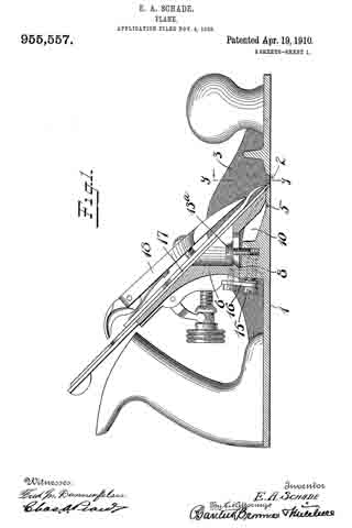
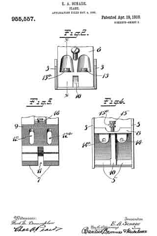
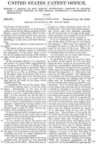
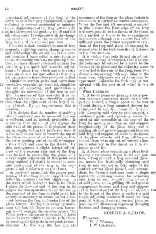
In the drawings — Figure 1 is a longitudinal section of a plane taken approximately on the plane of the line x–x of Fig. 2, certain parts being shown in elevation; Fig. 2 is a cross section of the body of the plane on the line y–y, Fig. 1, showing a portion of the plane frog in elevation; F ig. 3 is a view of the under side of the forward part of the plane frog; Fig. 4 is a plan view of that part of the body of the plane which supports the frog.
1 represents the sole of the plane body; 2 the throat therein, and 3–3 are the cheek pieces. Immediately to the rear of the throat 2 is a smooth bearing support 5 designed to receive a cooperating bearing surface 7 at the forward end of the frog 6. Still farther to the rear of the throat 2 is an elevated bearing support 8, the rear portion of which is constructed to receive and support a cooperating bearing surface 9 on the frog. The bearing supports 5–8 are spaced apart so that the frog will be supported at two different points.
10 is a longitudinally arranged guide and strengthening rib on the upper side of the sole of the plane extending rearwardly from a point at or near the throat 2.
11 is a groove or slot in the under side of the frog, the side walls of which are arranged to take a bearing upon the side walls of the rib 10 whereby said rib 10 will serve to hold the frog in correct aiinement and guide the frog in its movement to and fro, thereby avoiding any twist or lateral displacement of the frog as it is being adjusted.
12–12a are longitudinal slots in the frog, parallel with the groove 11 but somewhat to the rear of the same. These slots are arranged to receive clamping screws 13–13a respectively. The lower ends of these clamping screws take into threaded openings 14–14a respectively in the sole of the plane which openings are arranged forward of the most elevated portion of the support 8.
15 is an adjusting screw carried by the sole of the plane at the rear of and below the bearing 8. This screw has a groove 15a arranged to receive a yoke 16, which is secured to the rear of the frog. When the screw 15 is moved to and fro, it will impart a corresponding movement to the frog.
17 is the plane iron or cutter held in place on the frog by the usual cap 18.
In operation, the frog is secured in place by means of the screws 13–13a, the same being set down snugly so as to prevent accidental or unintentional displacement of the frog. The strain of these screws, as shown, comes upon an intermediate part of the frog between the supports 5–8. The plane iron and cap are then applied. The adjustment of the plane iron for the purpose of projecting or retracting the cutting edge of the same may be accomplished in any well known manner, that being immaterial to my invention. If it is found that the position of the plane iron, fore and aft, in the throat 2 should be changed, it is merely necessary to move the screw 15 in the proper direction and to the desired extent, producing thereby the desired movement and adjustment of the frog. If by chance (and it is practically impossible to prevent it) one of the screws 13 or 13a is screwed down more tightly than the other, it is obvious that any movement to and fro of the frog would tend to twist the same upon its bearing supports by reason of an abnormal drag on one side of the center line. The provision of the guide rib 10 which fits between the guide walls of the groove 11 will prevent this displacement. I have found that even though the screws 13–13a be screwed down very tightly nevertheless adjustment of the frog by means of the screw 15 alone may be readily effected, due doubtless to the smooth bearing supports 5–8 and the co-acting smooth bearing surfaces 7–9 and to the fact that there is sufficient elasticity or spring in the frog along the line of the clamping screws 13–13a to prevent the absolute locking of the frog. While the clamping engagement of the screws 13–13a is not sufficient to prevent the intentional adjustment of the frog by the screw 15, said clamping engagement is quite sufficient to prevent accidental or unintentional displacement of the frog, particularly as in this respect the guiding rib 10 and the adjusting screw 15 cooperate with the clamping screws 13–13a in the retention of the frog in any of its adjusted positions.
l am aware that heretofore separated frog supports, adjusting screws, clamping screws and reinforcing ribs are old but in the present instance I have added a new function to the reinforcing rib, viz., the guiding function, and have thereby produced a means for permitting the quick and accurate adjustment of a plane frog, which means is vastly more simple and far more effective than any adjusting means heretofore produced in that it eliminates certain parts and operations heretofore regarded as essential, simplifies the act of adjusting, and guarantees a straight line movement of the frog to and fro. ln devices of this character it is desirable that the plane iron should be in position when the adjustment of the frog is being effected. By my improvement this is possible.
It is obvious that the number of guiding ribs 10 employed may be increased, but one is sufficient, and is, indeed, preferable. It is obvious that the rib 10 may engage the side walls of the groove 11 throughout their entire length, but in the preferred form it is desirable to cut back or narrow the top of the rib to the rear of its front end, so that the active guiding part of the rib is comparatively short and close to the throat. By this arrangement a slight lateral adjustment of the extreme rear end of the frog may be had in assembling the plane, only a very slight adjustment at this point ever being required (if at all) to secure the accurate positioning of the frog on the supports 5 and 8 relatively to the throat.
In practice I accomplish the proper positioning of the frog on its support in the following manner: Before tightening up the screw which holds the fork in its place, I place the forward end of the frog in its proper position upon the rib and then swing the rear end of the frog to right or to left as may be necessary to secure perfect alinement between the frog and center line of the plane bottom. During this swinging movement the fork 16 (loose on its own fastening screw) engages the circular groove 15a. When perfect alinement is secured, I force home the screw which holds the fork, thereby securing all the parts in cooperative combination. In this way the fore and aft movement of the frog on the plane bottom is made to be in perfect alinement throughout. When the fore and aft movement is secured in this manner the front edge of the frog is always parallel to the throat of the plane. This method is found to be advantageous in practice, although it is evident that with sufficient pains the proper cooperative relations of the frog and plane bottom may be secured even if the fork were firmly fastened in the first instance.
It is evident that yoke 16 and the adjusting screw 15 may be reversed, that is to say, the yoke may be secured by a screw to the bottom of the plane and the adjusting screw be inserted in the rear of the frog, these two elements cooperating with each other in the same way, whichever one of them may be uppermost. Likewise the fork may be cast integral with the portion of which it is a part.
What I claim is:
1. A bench plane comprising a body portion having a transverse throat in the sole portion thereof, a frog support to the rear of said throat, a frog mounted thereon for adjustment to and fro, means for frictionally clamping said frog to said support, a combined guide and operating means located at and accessible at the rear of the frog for moving said frog on said support longitudinally of the plane body, and a guiding rib and groove engagement between said frog and support adjacent to the throat of the plane whereby said frog will be prevented from twisting out of correct alinement relatively to the throat as it is adjusted to and fro.
2. A bench plane comprising a plane body having a transverse throat in its sole portion, a frog support, a frog mounted thereon, means for frictionally clamping said frog to said support on both sides of the central vertical plane thereof, and intermediate its forward and rear ends a single positively operating means for adjusting said frog on said support longitudinally of said plane, and a guiding rib and groove engagement between said frog and support at the forward end of the frog and adjacent to the throat of the plane whereby the said single adjusting means will move the frog parallel with said central vertical plane regardless of difference of degree of clamping between said clamping means.
EDMUND A. SCHADE.
Witnesses:
W. J. WORAM,
I. W. CHAPMAN.