

No. 962,885 – Dovetail Tongue And Groove Cutter (Christian Bodmer) (1910)
| PLEASE NOTE: The images presented on this page are of low resolution and, as a result, will not print out very well. If you wish to have higher resolution files then you may purchase them for only $2.95 per patent by using the "Buy Now" button below. All purchases are via PayPal. These files have all been cleaned up and digitally enhanced and are therefore suitable for printing, publication or framing. Each zip package contains all the images below (some packages may contain more), and purchased files can be downloaded immediately. |
UNITED STATES PATENT OFFICE.
_________________
CHRISTIAN BODMER, OF NEW BRITAIN, CONNECTICUT, ASSIGNOR TO THE STANLEY RULE
& LEVEL COMPANY, OF NEW BRITAIN, CONNECTICUT, A CORPORATION OF CONNECTICUT.
DOVETAIL TONGUE AND GROOVE CUTTER.
_________________
962,885. Specification of Letters Patent. Patented June 28, 1910.
Application filed November 26, 1909. Serial No. 529,864.
_________________
To all whom it may concern:
Be it known that I, CHRISTIAN BODMER, a citizen of the United States, residing at New Britain, county of Hartford, State of Connecticut, have invented certain new and useful Iinprovements in Dovetail Tongue and Groove Cutters, of which the following is a full, clear, and exact description.
My invention relates to an improved means in the nature of a plane for forming dovetailed or undercut tongues and grooves.
The object of the invention is to provide a means for performing the above function which shall be so constructed as to permit the forming of such tongues or grooves with the greatest facility and accuracy.
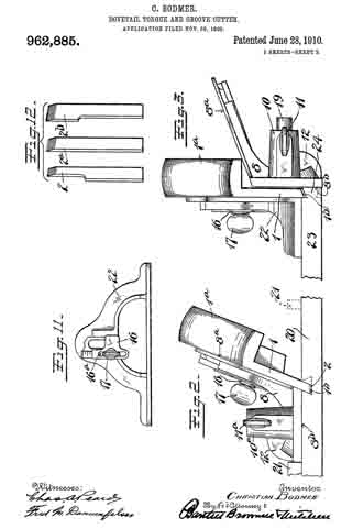
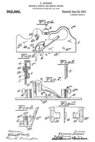
In the drawings, Figure 1 is a side elevation of the tool assembled and adjusted for the purpose of forming an undercut groove. Fig. 2 is a rear end elevation of Fig. 1, showing the tool as it appears in the act of forming a groove. Fig. 3 is an end elevation of the tool assembled and adjusted for the purpose of cutting a tongue. Fig. 4 is a side elevation of the main body and certain parts on a somewhat reduced scale. Fig. 5 is a view of the reverse side of the parts shown in Fig. 4. Fig. 6 is a sectional view on the line x–x of the Fig. 4, looking in the direction of the arrow. Fig. 7 is a side elevation of a guide frame, arranged for association with the main body of the plane. Fig. 8 is an end view of the guide frame shown in Fig. 7. Fig. 9 is a side elevation of a detail. Fig. 10 illustrates another detail in diderent positions. Fig. 11 is a side elevation of another guide frame arranged for association with the main body of the plane. Fig. 12 illustrates three different sizes of plane irons, on the scale indicated in Fig. 4. Fig. 13 is a side elevation of a detachable spur carrier.
1 is the main body or cutter carrier of the tool, the same being provided with a handle 1a and with a long narrow sole 1b.
2 is a cutter or plane iron, the cutting edge of the same being adjustable in a throat in the sole 1b.
3 is a clearance outlet for shavings or chips and located above the aforesaid throat.
4 is a clamp screw for locking the cutter in various positions of adjustment.
The cutter is located in a channel arranged obliquely in the side of the main body 1.
5 is a clutch operated by screw 4, for wedging down upon the cutter 2 when the latter is in position to prevent its unintentional or accidental dislodgment.
The oblique channel for receiving the plane iron is so arranged as to support the upper and lower surface of the shank of the cutter, the lower side of that part of the cutter opposite the recess 3 being supported on the incline 6. As will later be seen, cutters having cutting edges of different widths may be substituted, but to secure the best results the shank portion of each cutter should be substantially alike, the variations in sizes occurring at and directly above the cutting edge.
As will be seen by Figs. 2 and 3, the sole 1b of the body 1 is formed at an oblique angle to the opposite side walls thereof and in practice it is obvious that the edge of the cutter should be shaped to correspond.
7–7a are spurs arranged on opposite sides of the main body 1, both spurs being arranged to be projected to any desired degree or to be entirely retracted as desired. The function of said spurs is to score the wood in advance of the cutter 2, whereby, when said tool is used across the grain, the score lines made by the spurs 7–7a will prevent splintering the wood, thereby enabling the cutter 2 to plow out or to cut a clean channel. It should be stated that the width or thickness of the sole edge of the main body 1 is not greater than the minimum width of the smallest channel which it is possible to form.
The foregoing is a general description of the main body or cutter carrier element of the tool.
8 is the main body portion of what I term the composite guide frame, which frame is arranged for association with the cutter carrier 1 for the purpose hereinafter described.
8a is the side flange of the frame 8, said side flange being arranged obliquely to the sole 8b of said frame.
9 is an upright slot in the fiange 8a terminating at its lower end in an opening 9a.
10–10a are bosses, having passages therein at right angles to the sole 8b of the guide frame 8.
11–11a are set screws carried by the bosses 10–10a respectively.
12 is a thumb piece arranged to receive the thumb of the operator to facilitate the operation of the tool.
14 is a headed stud carried by the main body of the cutter carrier 1, the shank of said stud standing in the upright slot 9 of the frame 8 when the parts are assembled.
15 is a scale at one side of the slot 9.
16 is a gage arranged to co-act with the scale for the purpose hereinafter described. The gage 16 has a slot 16a. 17 is a set screw passing through slot 16a and into the body of the cutter carrier 1, whereby said gage may be adjusted up and down, said scale facilitating said adjustment.
18–18a are threaded holes arranged fore and aft in the body 1 of the cutter carrier, these threaded holes being arranged to receive the two guide posts, spaced apart properly to register with the sockets 10–10a of the guide 8. One of these guide posts is shown at 19, Fig. 3. These guide posts may be readily applied or removed by simply turning the screw end of each into the threaded openings 18–18a. These guide posts are used only when the tool is asembled for forming a tongue.
It will be observed that the stud 14 is arranged directly above the cutting edge of the plane iron 2, the purpose of this being later seen.
I will now describe the tool as assembled and employed in forming an undercut or dovetail groove. In this connection particular reference is directed to Figs. 1 and 2. In these figures it will be seen that the cutter carrier 1 is combined with the guide frame 8 and it may be assumed that the gage 16 is secured by the screw 17 on the scale 15 at the proper elevation to limit the depth of the cut. The intention now is to form a dove-tail groove in a piece of wood indicated at 20 (Fig. 2). To do this, the location of the groove is determined and a guide cleat 21 is tacked down to said piece of wood in a line parallel to the groove to be formed, and at one side thereof a distance corresponding to the width of the bottom of the sole 8b of the guide frame 8. The tool is then placed in the position indicated in Fig. 2 bearing against the cleat 21 and is moved to and fro until the cutter has descended into the wood 20 to the desired depth determined by stop 16. In forming this cut, both spurs 7–7a should be turned down, particularly if cut is to be made across the grain. The cutter carrier 1, being connected to the guide frame 8 only by the stud 14, may take an oscillating movement relatively to the guide frame 8 and hence may follow any warped portion of the wood in which the cut is being formed. By reason of the location of the stud connection 14 relatively to the cutter 2, the oscillating movement of the carrier relatively to the guide frame will not permit the cutter 2 to descend into any part of the wood 20 more than the amount predetermined by the gage 16. When an oblique groove has been cut as indicated in Fig. 2 the tool is removed and the cleat 21 is taken off and tacked down on the opposite side of the groove as indicated in dotted lines, being spaced apart from the adjacent edge to be of the groove a distance corresponding to the width of the bottom of sole 8a of the guide frame. The instrument is then turned around and operated as first described, the cutter 2 working down in the wood until the balance of the intended dove-tail groove is formed, as indicated in the dotted lines, Fig. 2. In forming this last part of the groove, it is unnecessary to employ the spur 7a which may be turned back into the position shown in Fig. 5, a recess in the said main body 1 receiving the same, so that it will stand flush, the spurs themselves being held in all positions by ordinary machine screws. The spur 7a will be seen to be unnecessary at this time because as the cutter descends, the wood on that side of the plane iron (the side toward the spur 7a) has previously been cut away in forming the first part of the groove, hence no chipping or splintering is possible on that side.
In forming a dove-tail tongue, another adjustment is employed, namely, the right angle guide 22, the same being substituted in the place formerly occupied by the guide 8, which latter is transferred to the opposite side of the frame 1 (as shown in Fig. 3) and mounted upon the posts 19–19, the sole 8b of the said guide 8, being spaced apart from the opposite side of the cutter carrier 1, a distance corresponding to the depth of the tongue to be formed. 23 represents the piece of wood upon which the dove-tail tongue is to be formed, said tongue portion being indicated at 24. The gage 16 is now adjusted on the scale 15 to such a position as to properly limit the descent of the cutter carrier 1. The instrument is placed in the position indicated in the Fig. 3, and moved to and fro. The right angle guide 22 cooperates with the guide 8 in holding the cutter carrier 1 in the proper position to cause the cutter to enter the wood as shown in Fig. 3, in which one-half of the tongue is represented as completed. In performing this work, the guide 8 obviates the use of a batten such as 21, although the latter could be used if desirable. To form the other half of the tongue 24 (indicated by dotted lines), the piece of wood 23 is simply turned over and the tool is used on the opposite surface in the same manner. In the formation of the tongue only one spur need be employed, namely the spur 7.
From the foregoing it will be seen that a dove-tail groove and a tongue of corresponding size and cross section may be formed with the greatest accuracy and ease.
Thus far I have described the device as fitted to produce tongues and grooves of the minimum size. When it is desired to produce a tongue and groove of greater size it is merely necessary to substitute a cutter having a cutting edge of greater width than the thickness of the sole 1b of the cutter carrier. When such wider cutter is employed it is obvious that one edge of the same will project beyond one side edge of the sole 1b, and in such an event, in order to provide a spur adjacent to that edge of the cutter, a supporting spur carrier or spacer 25 may be secured to the adjacent side of the main body 1. An illustration of this spacer 25 with the spur 7a is indicated in Fig. 13 and its construction is too obvious to require detailed description. The spacer 25 may be secured to the main body of the cutter by screws which may screw into threaded openings 27–27, Fig. 4.
28 is a projecting stud or screw head, which is arranged below the stud 14, the width of said screw head 28 being less than the width of the slot 9. This projecting head 28 is preferably employed to prevent unnecessary oscillation of the guides 8–22, relatively to the main body 1 of the plane iron carrier, but obviously it may be dispensed with.
In Fig. 12 I have shown cutters 2, 2a, 2b of three different sizes, said cutters being on a scale adapted to the scale of Figs. 4 and 5.
The frame 8 I have termed a composite guide, since it may be applied to either side of the cutter carrier. While in the drawings the outer edge of the guide 8 is shown as straight to furnish a bearing to parallel the sole of the cutter carrier, obviously this and other features may be modified in a variety of ways, so long as the results described are accomplished by means equivalent to those shown and in substantially the same way.
What I claim is:
1. In a tool of the character described, a cutter carrier comprising a body portion, a relatively long narrow obliquely arranged sole, a cutter therefor, a movable guide cooperating with said cutter carrier secured to the side thereof, said guide including a sole portion arranged obliquely to the adjacent side of the cutter carrier, the outer edge of said sole having a bearing paralleling the side of the sole portion of the cutter carrier.
2. In a tool of the character described, a cutter carrier including a long narrow sole arranged obliquely to the sides of the carrier, a bearing support for a cutter, and means for securing a cutter in said carrier, a cutter, a guide including two sides arranged obliquely, means for securing one of said sides to said cutter carrier, said means permitting said parts to partake of limited independent movement.
3. In a tool of the character described, a cutter carrier comprising a body portion, a long narrow sole portion arranged obliquely to the sides of the body, with means for supporting and securing the cutter, a cutter, means for holding said cutter carrier at an angle relatively to the work, and a connection between said means and said cutter carrier to permit said parts to move one on the other.
4. In a tool of the character described, a cutter carrier comprising a body portion, a long narrow sole portion arranged obliquely to the sides of the body, with means for supporting and securing the cutter, a cutter, means for holding said cutter carrier at an angle relatively to the work, a connection between said means and said cutter carrier to permit said parts to move one on the other, and means to limit the degree of movement of said parts in one direction.
5. In a tool of the character described, a cutter carrier comprising a body portion, a long narrow sole portion arranged obliquely to the sides of the body, with means for supporting and securing the cutter, a cutter, means for holding said cutter carrier at an angle relatively to the work, a connection between said means and said cutter carrier to permit said parts to move one on the other, and means to limit the degree of movement of said parts in one direction, said means being adjustable.
6. in a tool of the character described, a cutter carrier comprising a body, a long narrow sole at the base of said cutter carrier arranged obliquely to the sides, a cutter carried by said carrier, a scoring spur carried by said carrier at one edge of said sole and in advance of said cutter, and means for holding said cutter carrier at an angle relatively to the work, and a connection between said means and said cutter carrier arranged to permit relative independent movement of said parts without disturbing the angle of said cutter carrier to said work.
7. In a tool of the character described, a cutter carrier comprising a body, a long narrow sole at the base of said cutter carrier arranged obliquely to the sides, a cutter carried by said carrier, a scoring spur carried by said carrier at each edge of said sole and in advance of said cutter, means for holding said cutter carrier at an angle relatively to the work, and a connection between said means and said cutter carrier arranged to permit relative independent movement of said parts without disturbing the angle of said cutter carrier to said work.
8. In a tool of the character described, a cutter carrier including a body portion and a long narrow sole portion arranged obliquely to the sides of the body, and a guide including two obliquely arranged surfaces with means for operatively securing said guide to either side of said cutter carrier whereby in either position it will serve as a guide in the performing of work.
9. In a tool of the character described, a cutter carrier including a body portion and a long narrow sole portion arranged obliquely to the sides of the body, a guide including two obliquely arranged surfaces with means for operatively securing said guide to either side of said cutter carrier whereby in either position it will serve as a guide in the performing of work, and a second guide having right angle faces arranged under certain conditions to cooperate with said cutter carrier and the first mentioned guide.
10. In a tool of the character described, a cutter carrier including a body portion and a. long narrow sole portion arranged obliquely to the sides of the body, a guide including two obliquely arranged surfaces with means for operatively securing said guide to either side of said cutter carrier whereby in either position it will serve as a guide in the performing of work, and a second guide having right angle faces arranged under certain conditions to cooperate with said cutter carrier and the first mentioned guide, with means for permitting relative independent movement between said cutter carrier and said second guide without disturbing the operative angle of the cutter carrier to the work.
11. In a tool for forming undercut recesses, a cutter carrier comprising a main body and a relatively long narrow sole arranged obliquely to the sides of said body, a cutter carried by said carrier, a guide for said carrier, a sliding connection between said guide and carrier, a sole on said guide arranged obliquely to the side of said carrier when the parts are assembled in operative position, and a side bearing at the outer edge of said sole portion.
12. In a tool for forming undercut recesses, a cutter carrier comprising a main body and a relatively long narrow sole arranged obliquely to the sides of said body, a cutter carried by said carrier, a guide tor said carrier, a sliding connection between said guide and carrier, a sole on said guide arranged obliquely to the side of said carrier when the parts are assembled in operative position, a side bearing at the outer edge of said sole portion, and an adjustable stop for said sliding connection to limit the sliding movement of one part relatively to the other part in one direction.
13. In a tool for forming undercut recesses, a cutter carrier comprising a main body and a relatively long narrow sole arranged obliquely to the sides of said body, a cutter carried by said carrier, a guide for said carrier, a sliding connection between said guide and carrier, a sole on said guide arranged obliquely to the side of said carrier when the parts are assembled in operative position, a side bearing at the outer edge of said sole portion, an adjustable stop for said sliding connection to limit the sliding movement of one part relatively to the other part in one direction, and a scale on one of said parts arranged to cooperate with said stop.
14. In a tool of the character described, a cutter carrier including a main body, a relatively long narrow sole arranged obliquely to the sides of said body, a cutter carried thereby, a guide arranged to be secured to one side of said carrier, and a sole on said guide arranged obliquely to the side of the carrier, said securing means being arranged directly over the cutting edge of the cutter.
15. In a tool of the character described, a cutter carrier including a main body, a relatively long narrow sole arranged obliquely to the sides of said body, a cutter carried thereby, a guide arranged to be secured to one side of said carrier, and a sole on said guide arranged obliquely to the side of the carrier, said securing means being arranged directly over the cutting edge of the cutter, and including a stud and slot.
10. In a tool of the character described, a cutter carrier including a main body, a relatively long narrow sole arranged obliquely to the sides of said body, a cutter carried thereby, a guide arranged to be secured to one side of said carrier, and a sole on said guide arranged obliquely to the side ot the carrier, said securing ineans being arranged directly over the cutting edge of the cutter, and including a stud and slot, said stud being carried by the body of the carrier, said slot being formed in one side of the guide.
CHRISTIAN BODMER.
Witnesses:
W. J. WORAM,
I. W. CHAPMAN.