
| PLEASE NOTE: The images presented on this page are of low resolution and, as a result, will not print out very well. If you wish to have higher resolution files then you may purchase them for only $2.95 per patent by using the "Buy Now" button below. All purchases are via PayPal. These files have all been cleaned up and digitally enhanced and are therefore suitable for printing, publication or framing. Each zip package contains all the images below (some packages may contain more), and purchased files can be downloaded immediately. |
UNITED STATES PATENT OFFICE.
_________________
CHRISTIAN BODMER, OF NEW BRITAIN, CONNECTICUT, ASSIGNOR TO THE STANLEY RULE & LEVEL COMPANY, OF NEW BRITAIN, CONNECTICUT, A CORPORATION OF CONNECTICUT.
WOOD-SCORING DEVICE FOR PLANES AND THE LIKE.
_________________
968,508. Specification of Letters Patent. Patented Aug. 23, 1910.
Application filed November 30, 1909. Serial No. 530,556.
_________________
To all whom it may concern:
Be it known that I, CHRISTIAN BODMER, a citizen of the United States, residing at New Britain, county of Hartford, State of Connecticut, have invented certain new and useful Improvements in Wood-Scoring Devices for Planes and the Like, of which the following is a full, clear, and exact description.
My invention relates to improvements in wood cutting instruments such as planes and the like, the object being to provide in such constructions a scoring device or spur to partially cut the wood in advance of the plane iron.
A valuable incident of this invention is the provision of means whereby the scoring device or spur may be adjusted to cause said cutting edge to project to a greater or lesser degree from the main body of the instrument to make a shallow or a deep cut as required and to also compensate for variations in length of the spur due to sharpening the latter from time to time.
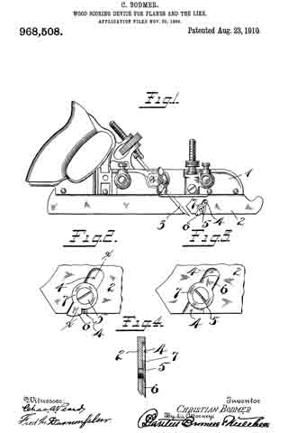
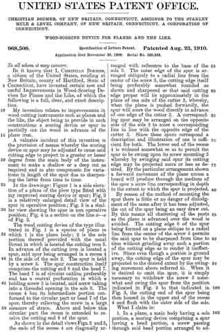
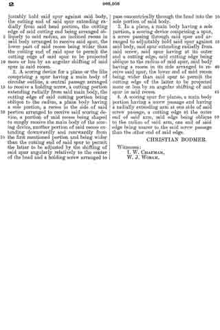
In the drawings: Figure 1 is a side elevation of a plane of the plow type fitted with my improved scoring device or spur; Fig. 2 is a relatively enlarged detail view of the spur in operative position; Fig. 3 is a similar view showing the spur in non operative position; Fig. 4 is a section on the line x–x of Fig. 2.
The wood cutting device of the type illustrated in Fig. 1 is a species of plane in which 1 is the plane body; 2 is the sole portion thereof provided with the usual throat in which is located the cutting iron 3. In advance of the cutting iron is located a spur, said spur being arranged in a recess 4 in the side of the sole 2. The spur is held by a screw 5. The spur construction itself comprises the cutting end 6 and the head 7. The head 7 is of circular outline preferably and has a central perforation in which a holding screw 5 is located, said screw taking into a threaded opening in the sole 2. The recess 4 has its intermediate portion conformed to the circular part or head 7 of the spur, thereby relieving the screw in a large measure of strain. Above and below this circular part the recess is extended to receive the cutting end 6 of the spur.
As shown in the detail views Figs. 2 and 3, the ends of the recess 4 are diagonally arranged with reference to the base of the sole 2. The outer edge of the spur is arranged obliquely to a radial line from the center of the screw 5, the cutting edge itself being preferably somewhat rounded as shown and sharpened so that said cutting edge proper will lie approximately in the plane of one side of the cutter 3, whereby, when the plane is pushed forwardly, the spur will score the wood directly in advance of one edge of the cutter 3. A corresponding spur may be arranged on the opposite side of the sole 2 to score a corresponding line in line with the opposite edge of the cutter 3. Since these spurs correspond a description and illustration of one is sufficient for both. The lower end of the recess 4 is widened somewhat so as to permit the spur to be swung upon its screw mounting 5 whereby by swinging said spur its cutting edge may be projected more or less as desired. By the particular arrangement shown a forward movement of the plane across a board will produce through the medium of the spur a score line corresponding in depth to the extent to which the spur is projected.
By reason of the method of mounting the spur there is little or no danger of dislodgment of the same after it has been adjusted, the cut of the spur being an easy draw cut. By this means all chattering of the parts as the plane is advanced over the wood is avoided. The cutting edge 6 of the spur being formed on a plane oblique to a radial line from the center of the screw 5 permits the said spur to be sharpened from time to time without grinding away such a portion of the cutting edge as to render it ineffective. Since even though a portion is ground away, the cutting edge of the spur may be projected to the desired extent by the swinging movement above referred to. When it is desired to omit the spur, it is simply necessary to withdraw the screw 5 somewhat and swing the spur from the position indicated in Fig. 2 to that indicated in Fig. 3, the cutting end of the spur being then housed in the upper end of the recess 4 and flush with the outer side of the sole.
What I claim is:
1. In a plane, a main body having a sole portion, a scoring device comprising a spur having a head portion, a screw passing through said head portion arranged to adjustably hold said spur against said body, the cutting end of said spur extending radially from said head portion, the cutting edge of said cutting end being arranged obliquely to said radius, an inclined recess in said body arranged to receive said spur, the lower part of said recess being wider than the cutting end of said spur to permit the cutting edge of said spur to be projected more or less by an angular shifting of said spur in said recess.
2. A scoring device for a plane or the like comprising a spur having a main body of circular outline, a central passage arranged to receive a holding screw, a cutting portion extending radially from said main body, the cutting edge of said cutting portion being oblique to the radius, a plane body having ca sole portion, a recess in the side of said portion arranged to receive said scoring device, a portion of said recess being shaped to snugly receive the main body of the scoring device, another portion of said recess extending downwardly and rearwardly from the first mentioned portion and being wider than the cutting end of said spur to permit the latter to be adjusted by the shifting of said spur angularly relatively to the center of the head and a holding screw arranged to pass concentrically through the head into the sole portion of said body.
3. In a plane, a main body having a sole portion, a scoring device comprising a spur, a screw passing through said spur and arranged to adjustably hold said spur against said body, said spur extending radially from said screw, said spur having at its outer end a cutting edge, said cutting edge being oblique to the radius of said spur, said body having a recess in its side arranged to receive said spur, the lower end of said recess being wider than said spur to permit the cutting edge of the latter to be projected more or less by an angular shifting of said spur in said recess.
4. A scoring spur for planes, a main body portion having a screw passage and having a radially extending arm at one side of said screw passage, a cutting edge at the outer end of said arm, said edge being oblique to the radius of said arm, one end of said edge being nearer to the said screw passage than the other end of said edge.
CHRISTIAN BODMER.
Witnesses:
I. W. CHAPMAN,
W. J. WORAM.