

| PLEASE NOTE: The images presented on this page are of low resolution and, as a result, will not print out very well. If you wish to have higher resolution files then you may purchase them for only $2.95 per patent by using the "Buy Now" button below. All purchases are via PayPal. These files have all been cleaned up and digitally enhanced and are therefore suitable for printing, publication or framing. Each zip package contains all the images below (some packages may contain more), and purchased files can be downloaded immediately. |
United States Patent Office.
RICHARD W. TANNER, OF ALBANY, NEW YORK, ASSIGNOR TO HIMSELF
AND SAMUEL J. DAVENPORT, OF SAME PLACE.
Letters Patent No. 97,833, dated November 14, 1869; antedated December 11, 1869.
_________________
IMPROVEMENT IN TOOL FOR CABINET-MAKERS.
_________________
The Schedule referred to in these Letters Patent and making part of the same.
_________________
To all whom it may concern:
Be it known that I, RICHARD W. TANNER, of the city and county of Albany, State of New York, have invented a new and useful Tool for Cabinet-Makers, and other workers of veneer; and I do hereby declare that the following is a full, clear, and exact description thereof, reference being had to the accompanying drawings, making a part of this specification, in which —
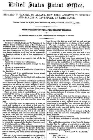
Figure 1 represents a perspective view of the invention.
Figure 2 is a vertical view of the same.
Figure 3 is a longitudinal section, through red line, in fig.2.
Figure 4 is a cross-section.
Figure 5 is a view of a modification of the form of the face-block.
Figures 6 and 7 are modifications, shown by end sections, of the said face-block.
Figure 8 represents the face-block with a plane-iron suited to this tool.
The nature of my invention consists in a tool-holder and a face-block properly secured together, and so arranged as to receive and hold a scraper or tooth-plane iron, or a straight plane-iron, or any other similar edge tool, by which the workmen plane, tooth, or scrape even the surface of the veneer.
There are many kinds of woods difficult to even on account of the waving or curling nature of the grain of the fibre. By this tool, any and all kinds of wood veneer may be evened and smoothed, with less labor and trouble, than with the hand-held tools now used.
The tool-holder may he constructed of wood or metal, and consists of a bar about a foot long, fur-
nished with a handle on each end, and is furnished with a holding-bar, pivoted to two eye-bolts, furnished with screws and set-nuts, also with a set-bolt, all of which are arranged and connected with the handled har, so as to fix and hold the scraper, plane-iron, or other similar tool, in any required position.
The face-block is secured to the said tool-holder by proper bolts or screws, and is provided with a mouth to permit the passage of the shavings from the wood, as it is being cut from off its surface.
To enable others skilled in the art to make and use my invention, I will proceed to describe it in reference to the drawings, and the letters of reference marked thereon, the same letters indicating similar parts.
One part of my invention consists in the tool-holder, constructed of the double-handled bar A, figs. 1, 2, and 3, and the tool-bar a, pivoted at each end, as shown in fig. 4, to the two eye-bolts e e, figs. 1 and 2.
The said eye-bolts e e pass through the handle-bar A, from the front to the rear, and are provided with thumb-nuts, by which the said tool-bar may be drawn nearer to the handled bar or further from it.
A screw-bolt, c, also works irorn the back ofthe handled bar A, and into it, and through to the tool-bar a, as shown in figs. 1, 2, and 3.
The scraper S, figs. 1 and 2, or plane-iron S’, fig. 8, is placed against the back of the tool-bar a, fig. 3, and between the handled bar A and the said tool-bar, and when thus placed, the said tool S or S’ is secured in its place, at any angle desired, by means of the said set-bolt c and eye-bolts e e.
The other part of my invention consists in the face-block B, shown in iigs. 1, 2. and 3.
The said face-block may be made of wood or metal, and is furnished with a mouth, b, the same as a plane, and may be either straight on its lower face, as in fig. 3, or concave, as in fig. 5, or the reverse, to fit the surface the tool is intended to operate upon, or they may be made either straight, or concave, or convex, longitudinally, as referred to, with moulding forms similar to those shown in figs. 6 and 7, or any other form, as may be required.
The said face-block is secured to the double-handled bar A., figs. 1, 2, and 3, by means of the screws o o, or their equivalents.
A plain flat face-block may be used, as shown in figs. 1 and 3, to which supplementary blocks B’ may be secured, as shown in figs. 5, 6, and 7, and when thus furnished in sets, together with the straps or plane-irons to correspond, the workman will have a tool which will enable him to perform and finish his work with greater ease and facility than can be done with the means they now have.
When a plane-iron, S’, is to be used, as in fig. 8, I would prefer to have the cutting-edge curved forward, as shown.
Having described my invention, What I claim, and desire to secure by Letters Pat~
ent, is —
The tool~holder, consisting of the block B, double-handled bar A, tool-bar a, eye-bolts e e, with their thumb-nuts, and the screw-bolt c, all arranged and constructed to operate as described, substantially as and for the purpose specified.
RICHARD W. TANNER.
Witnesses:
ALEX. SELKIRK,
J. A. BUCKBEE, Jr.