
| PLEASE NOTE: The images presented on this page are of low resolution and, as a result, will not print out very well. If you wish to have higher resolution files then you may purchase them for only $2.95 per patent by using the "Buy Now" button below. All purchases are via PayPal. These files have all been cleaned up and digitally enhanced and are therefore suitable for printing, publication or framing. Each zip package contains all the images below (some packages may contain more), and purchased files can be downloaded immediately. |
UNITED STATES PATENT OFFICE.
_________________
EDMUND A. SCHADE, OF NEW BRITAIN, CONNECTICUT, ASSIGNOR TO THE STANLEY RULE & LEVEL COMPANY, OF NEW BRITAIN, CONNECTICUT, A CORPORATION OF CONNECTICUT.
PLANE.
_________________
987,081. Specification of Letters Patent. Patented Mar. 14, 1911.
Application filed December 27, 1910. Serial No. 599,481.
_________________
To all whom it may concern:
Be it known that I, EDMUND A. SCHADE, a citizen of the United States, residing at New Britain, county of Hartford, State of Connecticut, have invented certain new and useful Improvements in Planes, of which the following is a full, clear, and exact description.
My invention relates to an improved frog adjustment for a bench plane, whereby the frog, which is the means for supporting the plane iron, may be readily adjusted to and fro, and which, when locked in position, is rigidly held in such a manner as to reduce to a minimum any chance of slippage or displacement.
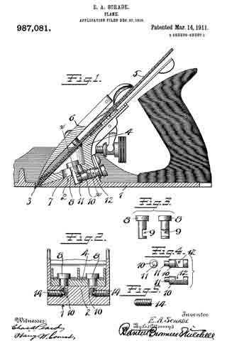
In the drawings, Figure 1 is a longitudinal section of a plane showing my improved adjustment. Fig. 2 is a section on the plane of the line x–x, Fig. 1, looking from left to right. Figs. 3, 4 and 5 are detail views. Fig. 6 is a longitudinal section of part of a plane of slightly modified construction from that shown in Fig. 1, my invention being applied thereto. Fig. 7 is a cross section on the line y–y of Fig. 6, looking from right to left. Fig. 8 is a longitudinal section of a part of a plane of another modified form. Fig. 9 is a cross section on the line z–z Fig. 8, looking from left to right. Fig. 10 is a longitudinal section illustrating still another modification. Fig. 11 is a cross section thereof on the line w–w looking from right to left.
Referring to Figs. 1 to 5, 1 represents a sole of an iron bench-plane which may be, as to general details, of conventional form. 2 is a frog bearing, in this particular instance formed on an incline directly to the rear of the throat 3. 4 is a frog adjustably mounted on the support 2 for movement to and fro relatively to the throat 3. 5 is a plane iron. 6 is a cap of conventional form and by which the plane iron may be clamped to the frog 4. The invention in this case resides primarily in the means for adjustably securing the frog 4 to the frog support 2. In this instance the frog is provided with two longitudinal slots or passages 7 in which stand clamping or gripping studs 8–8. These studs are headed, the headed portions standing above the slots, the opposite ends projecting down into cavities or recesses in the support 2. Each stud is transversely recessed toward its lower end, as indicated at 9. 10 is what I will term a cam stud, there being one for each gripping stud 8. The cam studs are arranged in the support 2, suitable bores being provided therefor, the rear ends of said studs being arranged to receive a suitable tool, for example, a screw driver, the forward end of each cam stud being provided with an eccentric projection or cam 11. This cam 11 projects into the recess 9 of the respective gripping stud. 12 is a slot in the side of each cam stud. Entering from the side of the plane is a locking screw 14, the same being so arranged relatively to the slotted portion 11 of the cam stud that the forward ends of each screw 14 will engage the wall at the base of the recess 12 at one side of, or eccentric to, the axis of the cam stud.
In the operation of the parts thus far described, it will be seen that by rotating the cam stud in the proper direction, the cam 11 will engage with the wall at the lower end of the recess 9 in the gripping stud so that said gripping stud will be pulled down into firm gripping engagement with the frog 4. To give a further set to the cam and to guarantee against disengagement, the screw 14 may be turned in until its nose engages eccentrically said cam stud, tending to turn it in a direction to increase the tension of the cam on the gripping stud and also preventing any rotation of the cam stud in a reverse direction to release said gripping stud. I have found, by this means, that the frog may be very quickly and easily adjusted, and, at the same time, when locked in position, is held with exceeding rigidity.
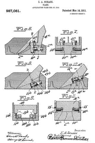
In the other views I have shown slight modifications. For example, in Figs. 6 and 7 I have shown the frog 4a as mounted upon a support 2a having a two-point bearing for the frog. In this case as before, the frog is held by means of gripping studs 8a operated by cam studs 10a which are in turn controlled by screws 14a.
In Figs. 8 and 9 I have shown a modification in which instead of providing the gripping studs 8 for holding the frog to its seat, I have provided the frog 4b with a plate-like extension 8b which is preferably cast into the frog, so as to be a permanent part thereof, said plate 8b having passages to receve the cam ends 11b of the cam studs 10b. In this case, as previously, the side screws 14b may be employed to cooperate with the cam studs for the same purpose as before.
In Figs. 10 and 11 I have shown a modification more particularly of the construction shown in Fig. 8 in that instead of anchoring the aforesaid plate in the frog, I have anchored a similar plate in the frog support. In these views, 8c represents said plate anchored in the support 2c, and in this case the cam studs 10c are carried in passages in the rear of the frog 4c, the cam ends 11c engaging the walls of the slot in the plate 8c in the same manner as the cam ends 11b engage the walls of the slot in the plate 8b, shown in Figs. 8 and 9. Here again take-up screws are employed, the same being indicated at 14c. In this case the take-up screws are carried by threaded bores in the sides of the frog, suitable windows or clearance openings 15 being provided in the cheek pieces of the plane to permit a screw driver to be entered sufficiently to engage the slotted ends of said screws 14c for the purpose of operating the same.
In both forms of devices shown in Figs. 8 to 11, a suitable clearance space is provided for the plates 8b and 8c respectively whereby there may be a relative movement between said plate and the part carrying the cam screw. In these cases, the cam ends 11b and 11c respectively should be of sufficient length to engage the plates 8b and 8c respectively in all of the various positions of adjustment.
What I claim is:
1. In a plane, a main body portion having a throat therein, a frog support at the rear of said throat, a frog adjustable to and fro thereon, a locking means for holding said frog in different positions of adjustment comprising a clamping member operatively engaged with one of said parts, means for operating said clamping member carried by the other part and comprising a rearwardly projecting cam stud coacting with said clamping member, and a lock and tightener for said cam stud, said lock and tightener comprising a laterally projecting exposed screw engaging said cam stud in a direction to turn the same as said lock and tightener is advanced.
2. In a plane, a main body portion having a throat therein, a frog support at the rear of said throat, a frog adjustable to and fro thereon, a locking means for holding said frog in different positions of adjustment comprising a clamping member operatively engaged with one of said parts, means for operating said clamping member carried by the other part and comprising a rearwardly projecting cam stud coacting with said clamping member, a lock for said cam stud, said lock comprising a laterally projecting exposed screw, and a shoulder on one side of said cam stud eccentric thereto, said screw engaging said eccentric shoulder and pressing against the same in a direction to turn said cam stud so as to more tightly engage the clamping member.
3. In a plane, a body portion having a throat, a frog support at the rear of said throat, a frog adjustable to and fro on said support and relatively to said throat, a clamping member carried by said frog and projecting into said support, said support having a recess therefor, a cam stud carried in said support and exposed at its rear end, an eccentric pin extension at the forward end of said stud eccentrically engaging said clamping member, and a lock screw for engaging said clamping stud at one side and arranged laterally thereto.
4. In a plane, a body portion having a throat, a frog support at the rear of the throat, a frog mounted for adjustment to and fro on said support, said frog having a fore and aft slot therein, a clamping stud passing downwardly through said slot into said support, an operating device for said clamping stud comprising a cam stud mounted in said support, an eccentric pin projection at the forward end of said cam stud eccentrically engaged with said clamping stud, and a lock for said cam stud.
5. In a plane, a body portion having a throat, a frog support at the rear of the throat, a frog mounted for adjustment to and fro on said support, said frog having a fore and aft slot therein, a clamping stud passing downwardly through said slot into said support, an operating device for said clamping stud comprising a cam stud mounted in said support, an eccentric pin projection at the forward end of said cam stud eccentrically engaged with said clamping stud, and a lock for said cam stud, said lock comprising a screw entering said frog support from the side of the plane.
6. In a plane, a body portion having a throat, a frog support at the rear of the throat, a frog mounted for adjustment to and fro on said support, said frog having a fore and aft slot therein, a clamping stud passing downwardly through said slot into said support, an operating device for said clamping stud comprising a cam stud mounted in said support and eccentrically engaged with said clamping stud, and a lock for said cam stud, said lock comprising a screw entering said frog support from the side of the plane, said screw engaging said cam stud eccentrically to rotate the same in a direction to increase the pressure on the clamping stud.
EDMUND A. SCHADE.
Witnesses:
W. J. WORAM,
H. S. WALTER.
Copies of this patent may be obtained for five cents each, by addressing the “Commissioner of Patents, Washington, D. C.”
_________________