No. 586,712 – Plane (Charles A. Paul) (1897)

[paiddownloads id=”531″]586712


UNITED STATES PATENT OFFICE.

_________________

CHARLES A. PAUL, OF ORLANDO, OKLAHOMA TERRITORY.

PLANE.

_________________

SPECIFICATION forming part of Letters Patent No. 586,712, dated July 20, 1897.
Application filed May 11, 1897. Serial No. 591,136. (No model.)

_________________

To all whom it may concern:

Be it known that I, CHARLES A. PAUL, a citizen of the United States, residing at Orlando, in the county of Logan and Territory of Oklahoma, have invented certain new and useful Improvements in Planes; and l do hereby declare the following to be a full, clear, and exact description of the invention, such as will enable others skilled in the art to which it appertains to make and use the same.

This invention relates to planes, and more particularly to plane-bits.

My object is to provide an improved and simple plane-bit which will be capable of quick and easy adjustment or removal.

The invention consists of certain novel features and combinations appearing more in detail hereinafter.

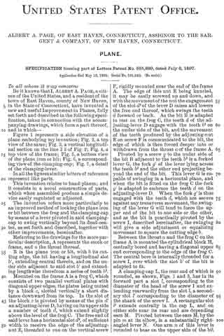
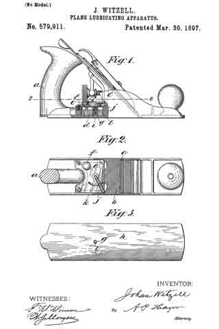
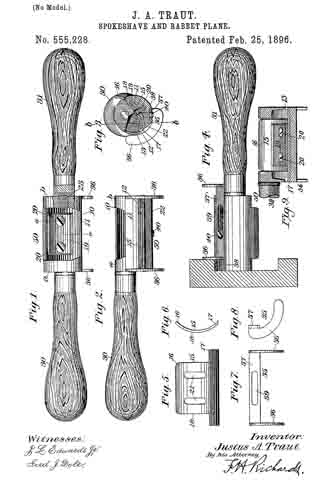
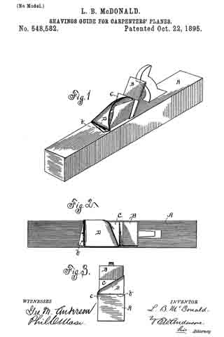
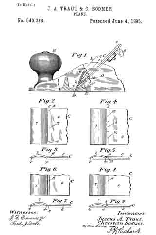
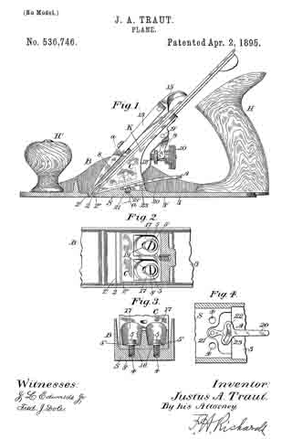
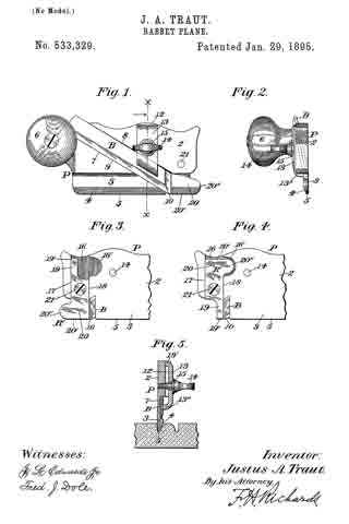
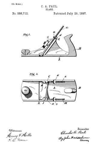
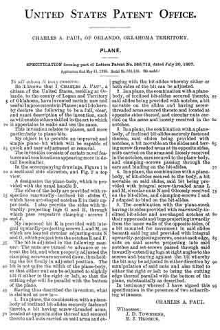
In the accompanying drawings, Figure 1 is a sectional side elevation, and Fig. 2 a top view.

A designates the plane-body, which is provided with the usual handle B.

The sides of the body are provided with respective rearwardly-inclined bit-slides C, which have arc-shaped notches E in their upper ends. I also proyide the sides with inwardly-projecting lugs G and H, through which pass respective clamping-screws I and J.

My improved bit K is provided with integral upwardly-projecting screws L and M, on which are located circular adjusting-nuts N and O, which project into the notches E and F.

The bit is adjusted in the following manner: The nuts are turned to advance or retreat the bit, and when properly adjusted the clamping screws are screwed down, thus holding the bit firmly in adjusted position. The bit is not quite the width of the plane-body, so that either nut can be adjusted to slightly tilt it either to the right or left, so that the cutting edge will lie parallel with the bottom of the plane.

Having thus described the invention, what is claimed as new is —

1. In a plane, the combination with a plane-body of inclined bit-slides securely fastened thereto, a bit having screw-threaded arms, located at opposite sides thereof and secured thereto and nuts carried on said arms and engaging with the bit-slides whereby either or both sides of the bit can be adjusted.

2. In a plane, the combination with a plane-body, of inclined bit-slides secured thereto, said slides being provided with notches, a bit movable on the slides and having screw-threaded arms secured thereto and located at opposite sides thereof, and circular nuts carried on the arms and loosely received in the notches.

3. In a plane, the combination with a plane-body, of inclined bit-slides securely fastened thereto, said slides being provided with notches, a bit movable on the slides and having screw-threaded arms at its opposite sides, nuts carried on the arms and loosely received in the notches, ears secured to the plane-body, and clamping-screws passing through the ears and binding on the bit-slides.

4. In a plane, the combination with a plane-body, of bit-slides secured to the body, a bit movable on said slides, said bit being provided with integral screw-threaded arms L and M, circular nuts N and O loosely received on the bit-slides, and clamping-screws I and J adapted to bind on the bit-slides.

5. The combination with the plane-stock having its sides provided with rearwardly-inclined bit-slides and arc-shaped notches at their upper ends and lugs projecting inwardly from the inner walls of the opposite sides, of a bit mounted for movement in said slides beneath said lug and provided with integral upwardly-projecting screws, one at each edge, nuts on said screws projecting into said notches and set-screws passed through said inwardly-extending lugs at right angles to the screws and bearing against the bit whereby the bit may be adjusted in either direction by manipulation of said nuts and also tilted to either the right or left to bring the cutting edge thereof parallel with the bottom of the plane, substantially as described.

In testimony whereof I have signed this specification in the presence of two subscribing witnesses.

CHARLES A. PAUL.

Witnesses:
J. D. TOWNSEND,
E. J. HEDRICK.

No. 585,889 – Plane (Albert A. Page) (1897)

[paiddownloads id=”530″]585889


UNITED STATES PATENT OFFICE.

_________________

ALBERT A. PAGE, OF EAST HAVEN, CONNECTICUT, ASSIGNOR TO
THE SARGENT & COMPANY, OF NEW HAVEN, CONNECTICUT.

PLANE.

_________________

SPECIFICATION forming part of Letters Patent No. 585,889, dated July 6, 1897.
Application filed May 16, 1896. Serial No. 591,46. (No model.)

_________________

To all whom it may concern:

Be it known that I, ALBERT A. PAGE, a citizen of the United States, and a resident of the town of East Haven, county of New Haven, in the State of Connecticut, have invented a new and useful Improvement in Planes, fully set forth and described in the following specification, taken in connection with the accompanying drawings, which form a part thereof, and in which —

Figure 1 represents a side elevation of a plane embodying my invention; Fig. 2, a top view of the same; Fig. 3, a vertical longitudinal section on the line 3 3 of Fig. 2; Fig. A, a top view of the frame; Fig. 5, a bottom view of the plane iron or bit, Fig. 6, a corresponding view of the clamping-cap; Fig. 7, a detail of the clamping-lever.

In all the figures similar letters of reference represent like parts.

This invention relates to hand-planes; and it consists in a novel construction of parts, which when assembled produce a simple device easily regulated or adjusted.

The invention refers more particularly to an improved method of locking the plane iron or bit between the frog and the clamping-cap by means of a lever pivoted in said clamping-cap to swing vertically beyond its dead-center, as set forth and described, together with other improvements, hereinafter.

Referring to the drawings for the more particular description, A represents the stock or frame, and a the throat thereof.

B is the plane iron or bit, with b its cutting edge, the bit having a longitudinal slot b’, extending central therein, and on the under side adjacent to said slot b’ and extending lengthwise therefrom a series of teeth b2.

Mounted on the frame A is a frog C, which consists of two parallel vertical plates with diagonal upper edges, the plates being united by a block c, slotted vertically a short distance downward from its top. In the slot of the block c is pivoted by means of the pin d’ an adjusting-lever D, having on its upper side a number of teeth d, which extend slightly above the level of the frog C. The free end of said lever has a horizontal slot d2, of sufficient width to receive the edge of the adjusting-nut E, threaded to run on the vertical screw F, rigidly mounted near the end of the frame A. The edge of this nut E being knurled, it may be easily screwed up and down, and with the movement of the nut the engagement of the slot d2 of the lever D raises and lowers the free end thereof, which swings the teeth d forward or back. As the bit B is adapted to rest on the frog C, the teeth d of the adjusting-lever D engage with the teeth b2 on the under side of the bit, and the movement of the teeth produced by the adjusting-nut E on screw F is communicated to the bit, the edge of which is then forced deeper into or withdrawn from the throat a of the frame A.

Pivoted by a screw g to the under side of the bit B adjacent to the teeth b2 is a forked lever G, the fork g’ of the lever lying across the teeth b2 and the other end projecting beyond the end of the bit. This lever G is capable of swinging in a horizontal plane, and when the bit is fitted on the frog C the fork g’ is adapted to embrace the teeth d on the adjusting-lever D. When the fork g’ is thus engaged with the teeth d, which are secure against any transverse movement, the swinging of the lever G will tend to force the upper end of the bit to one side or the other, and as the bit is practically pivoted by the screw I, described hereinafter, the swinging will give a side adjustment or equalizing movement to square the cutting edge b.

Between the throat a and the frog C on the frame A is mounted the cylindrical block H, centrally bored and having a diagonal upper end corresponding to the edge of the frog C. The central bore is internally threaded for a screw I, over which the slot b’ of the bit is adapted to fit.

A clamping-cap L, the rear end of which is rounded, as shown, Figs. 1 and 3, has in its forward part a slot l, corresponding to the diameter of the head of the screw I and extending rearwardly from the slot l, a secondary slot l’ corresponding to the diameter of the shank of the screw I. A rectangular slot l2 extends centrally in the cap L, and on either side near its rear end are depending ears M. Pivoted between the ears M, by the pin m at its elbow, is a substantially right-angled lever N. One arm n of this lever is rounded to bear on the upper side of the bit B, as hereinafter described, and the other arm n’ is formed to correspond with the upper side of the clamping-cap L, as shown in Figs. 1, 3, and 7, the extreme end being flattened and widened to act as a thumb-piece, Fig. 2.

When the clamping-cap is placed over the bit B, the slot l being fitted over the screw I and the cap forced forward so that the screw is engaged in the slot l’, the right-angled lever H is used as a clamp to hold the parts together and rigidly secure them in place.

Upon the forward movement of the arm n’ the other arm n bites against the bit B, and the tendency is to force the clamping-cap L forward into closer engagement with screw I, Fig. 3.

The slight elasticity in the cast metal allows the clamping-cap to be raised as the arm n of the clamp passes the perpendicular, so that when in the position shown in Fig. 1 the parts are securely locked. The screw I may be raised or lowered to secure the right adjustment of the clamping-cap and clamp. The forward position of the clamp when the parts of the plane are locked and its conformity with the surface of the clam ping-cap makes a smooth handle and prevents the hand of the operator from being caught on the clamp when the plane is in use.

A finger-knob P is shown in the forward part of the frame beyond the throat, which may also serve as an adjusting-screw for a sliding throat-piece, as is often the case.

Having now described my invention, what I claim, and desire to secure by Letters Patent, is —

In a plane, the combination with the frame; of the bit; a support on the frame for the bit; a locking device mounted on the frame, a clamping-cap above the bit, forming the main handle portion of the plane, and having its forward end adapted to engage with said locking device to lock the forward end of the bit, while its rear end is provided with a longitudinal slot; a substantially right-angled clamp pivoted in said clamping-cap, with one arm adapted to swing forward in said longitudinal slot, and the other arm to bear on the bit and lock; the rear of the same, when the forwardly-swinging arm has assumed a position in alinement with the main portion of said clamping-cap; and means on said clamp for disengaging it from its locked position, substantially as described.

In witness whereof I have hereunto set my hand, at New Haven, in the county of New Haven, State of Connecticut, this 11th day of May, 1896.

ALBERT A. PAGE.

Witnesses:
WILLIAM T. COOKE,
CHARLES L. BALDWIN.

No. 584,002 – Plane-Guide (Erick Lindfors) (1897)

[paiddownloads id=”529″]584002


UNITED STATES PATENT OFFICE.

_________________

ERICK LINDFORS, OF MINNEAPOLIS, MINNESOTA.

PLANE-GUIDE.

_________________

SPECIFICATION forming part of Letters Patent No. 584,002, dated June 8, 1897.
Application filed May 7, 1895. Serial No. 548,413. (No model.)

_________________

To all whom it may concern:

Be it known that 1, ERICK LINDFORS, a citizen of the United States, residing in the city of Minneapolis, county of Hennepin and State of Minnesota, have invented a certain new and useful Improvement in Plane-Guides, of which the following is a specification.

My invention relates to means for guiding jointer-planes and in any other kinds of planes, and its object is to provide an adjustably-connected wing or guide whereby the plane may be used for squaring or beveling at different angles the surface operated upon.

In the accompanying drawings, illustrative of my improvements, there is shown in Figure 1 a plan view of the skeleton of a device embodying my improvements; and in Fig. 2 a transverse section of the same, showing by full and dotted lines different positions of the guiding member relative to the tool while being used for different purposes.

In such drawings a metallic or other suitable frame or stock for carrying a plane-iron is shown by the reference Fig. 1, and the slot in the sole through such iron or bit may be introduced, secured, and adjusted in the ordinary way is shown at 2. The stock shown is a skeleton metal one, but it may be of wood, and a handle (not shown) should of course be provided for operating the tool. These features may be of any usual or suitable construction, for they form no part of the present improvement and are referred to only for the purpose of showing the relationship of the improvement to a form of tool that is well known.

At the side of the tool is suitably hinged, as by means of a wire 3 or pintles, in sockets 4, a wing 5, which serves as the guide in the operation of the tool. This wing has formed on or attached to it an arm 6, on which is formed or to which is attached a suitably-curved extension 7, which may be round or of any suitable shape. These latter members 6 and 7 are arranged to pass through a suitable opening in the side of the stock and the arm 7 to pass through a guiding member 8, supported within the stock by a partition 9 or other suitable support within the body 1, and a set-screw 10 (or other regulating device) is provided for engaging the part 7 to hold it in place in the guide, so as to hold the guide-wing 5 in desired positions of adjustment. As illustrated, the arm 6 and its entension 7 are connected by a pivot 11, and the guide 8 for the part 7 is swiveled in the partition 9. By these means the wing can be turned from an upward to a downward position through an are of about a half-circle, and it may be held in adjustment at any intermediate point by the set-screw 10. The tool may be used in the ordinary way and for the usual purpose of dressing lumber when the wing 5 is in position shown by the full lines in the drawings or is turned upward from such position, and when turned downward, as indicated at a in Fig. 2, it will serve to guide the tool and direct its cutting, so as to form a bevel on the board that is being cut. It will be understood that the wing 5 may be placed either on the upper or side surface of the board to be dressed, depending upon the work desired to be done, so that the blade of the tool as it is advanced will out in a course determined by the angle of inclination of the adjustable member 5, and so by the desired adjustment of this member 5 the tool can be utilized to cut or smooth surfaces within a range of ninety degrees, and by suitable graduations supplied on the arm 7 the degrees of adjustment can be accurately determined and fixed.

Having described my invention, what I claim is —

In a plane, the combination with a stock having a slot in its side and a cavity in its interior, of a guide-wing hinged to the stock adjacent to the slot therein, the curved extension 7 pivotally secured at one of its ends on the guide-wing and entering the slot in the stock, the guide 8 swiveled on the interior of the stock, and having a transverse opening for the reception of the extension 7, and a set-screw to fixedly secure said extension, substantially as described.

ERICK LINDFORS.

Wlitnesses:
ANDREW LIDEN,
J. W. PETERSON.

No. 579,911 – Plane-Lubricating Apparatus (Johan Witzell) (1897)

[paiddownloads id=”528″]579911


UNITED STATES PATENT OFFICE.

_________________

JOHAN WITZELL, OF NEW YORK, N. Y.

PLANE-LUBRICATING APPARATUS.

_________________

SPECIFICATION forming part of Letters Patent No. 579,911, dated March 30, 1897.
Application filed June 13, 1896. Serial No. 595,434. (No model.)

_________________

To all whom it may concern:

Be it known that I, JOHAN WITZELL, a citizen of the United States,and a resident of New York city, in the county and State of New York, have invented certain new and useful Improvements in Plane-Lubricating Apparatus, of which the following is a specification.

My invention consists of improved means of periodically supplying lubricating-oil to the working face of the plane, as hereinafter described, reference being made to the accompanying drawings, in which —

Figure 1 is a side elevation of a wood-plane with a part in section, showing the application of my improved lubricating apparatus. Fig. 2 is a horizontal section of the plane on line 2 2, Fig. 1. Fig. 3 is a plan of the plane inverted.

Between the handle a and the seat b of the plane-bit c I provide an oil-reservoir d in any approved way with a suitable cover e, said cover having a plugged filling-aperture, as indicated at f, and I provide a lubricating-passage g through the bottom of the reservoir to the working face h of the plane with a valve i to open and close the same, said valve being on the lower extremity of a vertical stem j, extending up through the cover and thereat provided with a horizontal lever-arm j, normally extending from the stein located midway between the sides of the plane or thereabout to the right-hand side and inclined forward relatively to the lengthwise direction of the plane, about as represented in Fig. 2, so that it is convenient to engage the arm with one of the fingers of the hand holding the plane by the handle and working the plane and pull the arm backward to open the valve, which being thus pulled back is made to raise and open the valve by the curved inclined way k, which I have provided on the cover e for such effect.

Within the reservoir and between the cover e and the valve-top I have provided a coiled spring l, which presses downward on the valve and closes it when the arm j is released by the operator, the declivity of the way k being such that pressure of the spring will cause the arm to slide on it freely.

It will be seen that with my improved apparatus the supply of oil can be controlled at will and without interrupting the work. It will also be seen that the location of the lubricator between the seat of the plane-bit and the handle is more favorable for uniform lubrication of the working face throughout its entire length than when located in the knob forward of the bit. Besides the knob so utilized is not as reliable and serviceable for withstanding the hammer-shocks for jarring the bit slack as when solid and the shocks of the hammer are liable to force out spurts of oil.

I claim —

In a plane-lubricator, the combination of the reservoir located between the seat of the plane-bit and the rear handle of the stock, and having a passage communicating with the working face of the plane, the valve seated in said passage and having a stem extending upward through the cover of the reservoir, spring arranged between the cover and the head of the valve for closing said valve, the inclined way on the cover of the reservoir, and the arm of the valve-stem ranging over said inclined way in the relation to the handle for opening the valve by a finger of the hand gripping said handle substantially as described.

Signed at New York city, in the county and State of New York, this 11th day of May, A. D. 1896.

JOHAN WITZELL.

Witnesses :
CHARLES BRETTELL,
GEORGE BRETTELL.

No. 556,835 – Carpenter’s Plane (George S. Smith) (1896)

[paiddownloads id=”527″]556835


UNITED STATES PATENT OFFICE.

_________________

GEORGE S. SMITH, OF GRAND RAPIDS, MICHIGAN.

CARPENTER’S PLANE.

_________________

SPECIFICATION forming part of Letters Patent No. 556,835, dated March 24, 1896.
Application filed April 20, 1894. Serial No. 508,365. (No model.)

_________________

To all whom it may concern:

Be it known that I, GEORGE S. SMITH, a citizen of the United States, residing at Grand Rapids, in the county of Kent and State of Michigan, have invented certain new and useful Improvements in Carpenters’ Planes; and I do hereby declare the following to be a full, clear, and exact description of the invention, such as will enable others skilled in the art to which it appertains to make and use the same.

My invention relates to an improved carpenter’s plane; and its object is to provide the same with certain new and useful features hereinafter more fully described and particularly pointed out in the claims, reference being had to the accompanying drawings, in which —

Figure 1 is a longitudinal vertical section, on the line 1 1 of Fig. 2, of a device embodying my invention 5 Fig. 2, a plan view of the same with the blade and wedge removed; Fig. 3, a vertical section on the line 3 3 of Fig. 1; Fig. 4, an inclined transverse section on the line 4 4 of Fig. 1, and Fig. 5 details showing openings to receive the adjusting-screw H.
Like letters refer to like parts in all of the figures.

A is the main frame of the plane, B the blade-supporting block, C the blade, D the wedge, E the adjusting-lever, and F the adjusting-screw, all being ot the usual construction.

In a suitable opening near the upper end of the blade-block B and laterally movable therein is a bar G, having a widened outer end, which is formed with lugs G’ to engage the sides of the blade and shift it laterally to square the edge of the same with the under surface of the plane. Said bar G is provided at its lower side with a screw-threaded concave surface engaging the side of a screw H. Said screw is provided with a milled head I and journaled in openings J’ J” in lugs J on the back of the block B. Said openings are elongated in the direction of the bar G, and one of the bearings of the screw H is reduced, and the corresponding opening J” is reduced at the lower end to engage this reduced bearing, whereby the screw is prevented from moving longitudinally.

The bar G is held in place in the block B by a screw K, the head of which screw overlaps said bar at one side for this purpose. By removing this screw K and bar G the screw H may be moved into the upper ends of the openings J’ J” and thence removed longitudinally, and when in place said screw is held by the engaging screw-threaded side of the bar G.

Within a suitable recess in the bottom of the plane and with its rear angle close to the cutting-edge of the blade C is a throat-slide L, having upwardly-projecting bosses L’, extending through elongated openings R. Screws P are inserted in said lugs, whereby the slide L is held in the recess and permitted to move longitudinally therein. A spring N is attached to a suitable yoke-frame M at its upper end and engages the slide L at its lower end to press said slide toward the blade C. A screw O engages said spring and a transverse rib Q, and serves to adjust the spring to determine the approach of the slide L to the blade C and thus adjust the opening or throat in front of said blade. Said block L, being movable and pressed toward the blade C by the spring, will yield to the shaving as it passes through the throat. It can therefore be adjusted very close to the blade and thus cause the tool to do very smooth work.

I am aware that a throat-block of somewhat similar construction to mine and capable of being adjusted to and from the blade has heretofore been patented, but said throat-block was not provided with a spring and was incapable of automatically yielding to the shavings, for which reason it did not prevent clogging of the throat.

I am also aware that an adjustable spring has been proposed to take the place of the sliding throat-block, which spring will of course yield to the shaving passing up through the month of the plane, but it will yield for a time only during the operation of the plane, as the space between its forward surface and the forward wall of the throat soon receives a sufficient quantity of shavings to force and hold the spring into contact with the cutter, thus not only preventing the spring from yielding, but entirely closing the exit for the shavings. By combining the sliding throat-block with a spring, which causes it automatically to yield to the quantity of shavings passing upward into the throat of the plane, said throat will not become choked and an open exit for the shavings is kept at all times, as will be readily seen.

What I claim is —

1. In a plane, the combination with the blade and its supporting-block, said block having elongated openings one of which has a reduced lower end, of a bar, laterally movable in said block, and engaged with said blade, an adjusting-screw for the bar and blade, said screw being seated in said openings in the block and having a reduced end corresponding with the reduction in the end of one of said openings, and a screw in said block, having its head overlapping one side of said bar and securing the same in place.

2. In a plane, the combination with the blade and its supporting-block, said block having an opening near its upper end and also having lugs formed with elongated openings, one of which latter has a reduced lower end, of a bar laterally movable in said block, said bar having a widened end formed with lugs engaging the sides of the blade, an adjusting-screw for the bar and blade, said screw being seated in the openings in the lugs of the block and having a reduced end corresponding with the reduction in the end of one of said openings, and a screw in said block having its head overlapping one side of said bar and securing the same in place.

3. In a plane, the body, having a recess in its under side adjacent to its throat, and also having an elongated opening, an upwardly-projecting rib and a yoke-frame, in combination with a movable throat-block in said recess, having an end extending upward into the throat of the plane and a boss extending through said elongated opening, a screw engaging said boss, a spring secured at its upper end to said yoke-frame and having its lower end engaged with the upturned end of said throat-block, and an adjusting-screw engaging said rib and spring, substantially as described.

4. In a plane, the body having a recess in its under side adjacent to its throat, in combination with a sliding throat-block within said recess, said block having an upturned part, and a spring engaging said upturned part of the throat-block and causing the latter automatically to adjust itself to the quantity of the shavings passing upward into the throat of the plane, substantially as described.

In testimony whereof I affiix my signature in presence of two witnesses.

GEORGE S. SMITH.

Witnesses:
LUTHER V. MOULTON,
LOIS MOULTON.

No. 556,608 – Oiling Attachment (Theodore Martin Anderson) (1896)

[paiddownloads id=”526″]556608


UNITED STATES PATENT OFFICE.

_________________

THEODORE MARTIN ANDERSON, OF NEW WHATCOM, WASHINGTON.

OILING ATTACHMENT.

_________________

SPECIFICATION forming part of Letters Patent No. 556,608, dated March 17, 1896.
Application filed March 8, 1895. Serial No. 541,035. (No model.)

_________________

To all whom it may concern:

Be it known that I, THEODORE MARTIN ANDERSON, of New Whatcom, in the county of Whatcom and State of Washington, have invented a new and Improved Oiling Attachment, of which the following is a full, clear, and exact description.

This invention relates to certain improvements in oiling or lubricating attachments, and has for its object to provide an attachment of this character especially designed for application to carpenters’ planes and the like to reduce the friction between the plane and the wood being dressed.

The invention will be hereinafter fully set forth and its novel features carefully defined in the claim.

Reference is to be had to the accompanying drawings, forming a part of this specification, in which similar figures of reference indicate corresponding parts in all the views.

Figure 1 is a vertical longitudinal section taken through a plane of ordinary construction provided with my improvements. Fig. 2 is a transverse section taken through the oil-chamber in the plane indicated by the line 2 2 in Fig. 1. Fig. 3 is a side elevation showing the device for regulating the attachment. Fig. 4 is a view similar to Fig. 1, showing another form of my invention. Fig. 5 is a transverse section in the plane indicated by the line 5 5 in Fig. 4. Fig. 6 is a view similar to Fig. 4, illustrating still another modified form of the device. Fig. 7 is a transverse section in the plane indicated by the line 7 7 in Fig. 6, and Fig. 3 is a transverse section showing another modification which will be hereinafter described.

Referring primarily to Figs. 1, 2 and 3, 1 represents a plane of any preferred construction having a bit 2 and provided with parallel upwardly-extending side pieces or flanges and having at its rear part, behind said bit, an oil-chamber 3, having an outlet 4. extending across the under side of the plane-stock. As clearly seen in Figs. 1 and 2, the receptacle or chamber 3 for the oil is provided with a cover 7 arranged to slide in grooves 6 6 formed in the opposite side pieces of the plane.

The chamber or receptacle 3 will be filled with any suitable lubricating material — as for example, cotton waste or wool saturated with oil — and a wick 5 of any suitable kind is arranged in the said chamber, adapted to extend with its lower end through the outlet 4 to the under side of the stock. In order to adjust this wick 5, I employ disks 3 having spurs, said disks being mounted on a shaft 9 extending through the chamber 3 and provided at one end with a thumb-piece 10 arranged in a recess 10a in the outer face of the plane, as clearly seen in Figs. 2 and 3. By this construction it will be seen that when it is desired to use the attachment the thumb-piece 10 may be turned to move the wick down into contact with the surface of the wood to be dressed, and the oil will flow through the said wick and become evenly distributed over the lower face of the plane so as to reduce the friction.

When it is not desired to use the attachment, the thumb-piece 10 may be turned in a reverse direction so as to raise the wick 5 above the under side of the plane, as shown in Fig. 1.

In the construction seen in Figs. 4 and 5 I employ in lieu of the disks 8 and shaft 9 an eccentric 15 mounted on a shaft 12 and arranged to work in a slot formed in a block 16, having a serrated edge adapted to engage and hold the wick 5. The shaft 12 is screw-threaded to receive a nut 14 to hold the block 16 in place, and is provided at its outer end with a thumb-piece 13. Thus it will be seen that as the thumb-piece 13 is turned the block 16 will be moved up and down in the oil-chamber 3, carrying with it the wick 5.

In the construction seen in Figs. 6 and 7 the chamber 3 is provided with a slot 11 in its rear wall, and in said chamber is pivoted at 13 a lever 17, the rear end of which projects through the slot 11. The forward end of the lever 17 is bifurcated, and in its bifurcations is journaled a roller 19 having a wearing-surface covered with cloth or the like, and the periphery of said roller 19 extends through an opening in the bottom of the oil-chamber 3 into contact with the surface of the wood to be dressed. Behind the chamber 3 is located a spring 20, the arms of which are bent up and adapted to hold the projecting rear end of the lever 17, whereby said lever, when depressed to stop the flow of oil, will be held in its depressed position. In this form of the attachment the receptacle 3 is provided with a hinged cover 7x.

It is not essential that the wick employed in the construction shown in Figs. 1 and 4 shall extend entirely across the under side of the plane-stock. In some cases the chamber 3 may be provided with a series of outlets 4x as indicated in Fig. 8, and each of these outlets may be provided with a separate wick 5x, as will be readily understood. If desired, the wick may be in front of the bit instead ef behind the same, as shown.

From the above description of my invention it will be seen that the same is capable of considerable modification, and for this reason I do not wish to limit myself to the precise construction herein shown.

Having thus described my invention, I claim as new and desire to secure by Letters Patent —

A plane having a base portion formed with parallel and perpendicular sides having a block arranged between them and arising from the base portion, and a bit mounted between said sides and supported by the block, the block having an oil-chamber therein, substantially as described.

THEODORE MARTIN ANDERSON.

Witnesses:
H. H. ELLS,
G. H. BACON.

No. 556,114 – Core-Box Plane (Justus A. Traut) (1896)

[paiddownloads id=”525″]556114


UNITED STATES PATENT OFFICE.

_________________

JUSTUS A. TRAUT, OF NEW BRITAIN, CONNECTICUT.

CORE-BOX PLANE.

_________________

SPECIFICATION forming part of Letters Patent No. 556,114, dated March 10, 1896.
Application filed September 18, 1895. Serial No. 562,829. (No model.)

_________________

To all whom it may concern:

Be it known that I, JUSTUS A. TRAUT, a citizen of the United States, residing at New Britain, in the county of Hartford and State of Connecticut, have invented certain new and useful Improvements in Core-Box Planes, of which the following is a specification.

This invention relates to planes adapted for planing concaved surfaces of different areas, and more particularly designated as a “core-box” plane; and the object of the invention is to provide a plane having supplemental side extension-plates, whereby each or both sides of the stock can be extended to different widths and whereby the plane is rendered serviceable for finishing and planing core-boxes of a wide range of sizes, and also for use in connection with other concaved surfaces.

A further object of the invention is to provide a fastening means whereby the supplemental side extension-plates can be reversed and interchanged, or whereby they can all be secured to one side of the stock, and which fastening means is simple and easily and quickly manipulated.

In the accompanying drawings, forming part of this specification, Figure 1 is a top view of a core-box plane constructed in accordance with this invention. Fig. 2 is an interior side view of one side of the plane, the other side thereof being removed and showing the juncture of the stock in section. Fig. 3 is a transverse sectional view in line a a, Fig. 1, looking toward the right hand thereof. Fig. 4 is an end view of the plane and shows same in position for planing one-half of a the core-box of comparatively-small size, and also shows the supplemental plates removed. Fig. 5 is a view similar to Fig. 4, illustrating the plane in use upon one-half of a core-box of larger size and having a supplemental side plate in position on each side of the stock; and Fig. 6 shows the plane in use on one-half of a core-box of comparatively-large size with the supplemental side plates in position on one side of the stock.

Similar characters of reference designate like parts in all the figures of the drawings.

The plane consists, in the preferred form thereof herein shown and described, of a suitable stock or relatively-thin plate 10, preferably constructed to form two diverging side plates 11 and 12, preferably extending at right angles to each other and joined at their inner edges. Adjacent to the juncture of the side plates, and preferably substantially midway of the length thereof, the stock is provided with a mouth or mortise 13, which is preferably shown forming an acute angle, and likewise preferably has its vertex at the point of juncture of the side plates. Adjacent to the mouth 13 on the interior of the side plates and adjacent to the juncture thereof the stock has the usual inclined bed 14 for the plane-iron, formed either integrally therewith or removably secured thereon in any suitable way as desired.

The plane-iron 15, which is shown herein having an acute-angled cutting-edge, is removably and adjustably seated on the bed 14; and secured thereto by the usual fastening and clamping means, which is shown consisting of the clamping plate or wedge 16 and the thumb-screw 17. The plane-iron 15, when in its normal operative position, has its cutting-edge projecting at the desired angle below the mouth of the stock, whereby each side plate of the stock will have one-half of the cutting-edge of the plane-iron extending therein.

Adjacent to the juncture of the diverging side plates 11 and 12 on the interior of the stock a suitable toat or handle 13 is secured in any suitable way and is shown herein clamped by means of a screw 20 to a bed 19, preferably formed integral with the side plates. Adjacent to the forward end of the stock, and likewise on the interior thereof and adjacent to the juncture of the side plates, a suitable knob or hand-rest 21 is likewise secured by means of a screw 22 and bed 23 in substantially a similar way to that of securing the toat 18.

The above-described plane is commonly known as the “core-box” plane and forms no part of my present invention, except in so far as the plane constitutes a basis for the same.

Heretofore in practice when necessary to plane or finish core-boxes of different sizes it has been the usual case to provide a plane sufficiently large to plane the largest size of core-box desired to be constructed, which plane, when used in connection with core-boxes having comparatively-small diameters, is extremely clumsy to use, and when desirable to obviate this disadvantage it has been the usual practice to construct core-box planes of different sizes for work on different sizes of core-boxes, which is not only expensive but a great disadvantage when it is desired to make a number of different sizes of such boxes. In order, therefore, to obviate these disadvantages I have provided, in connection with a core-box plane of any suitable and desired construction, a suitable attachment in the nature of a guide or rest and which guide or rest is adjustable and attachable to either or both sides of the stock, as desired, and in the preferred form thereof herein shown and described preferably consists of a supplemental extension plate or plates adapted to be secured to the stock with one of its edges in parallelism with the free edge of one of the side plates forming the stock by means of a suitable fastening device. In the construction shown two of these supplemental extension-plates are provided and designated in a general way by 25 and 35. These plates may be constructed of any desired thickness and width, but are preferably constructed of about the same width as the side plates forming the stock and of sufficient thickness to permit the outer side face thereof to be in alignment with the outer side face of the adjoining side plate of the stock when the supplemental plates are in position on the stock. These plates are likewise constructed of any suitable material, but preferably of the same material as the stock, which is usually of metal, and each plate is adapted to rest on the free edge of one of the respective stock-plates 11 and 12, with one of its edges in parallelism therewith, or on the free edge of a supplemental side plate 25 or 35. As a means for securing these supplemental extension side plates in position, the side plates 11 and 12 of the stock on the interior thereof are provided with any desired number of socketed brackets 26, preferably formed integral with such side plates, and in the construction shown each side plate of the stock is provided with two of these brackets 26, one near each end thereof. These brackets are provided with clamping devices projecting through the walls and intersecting the sockets thereof at right angles thereto, and in the form shown these clamping devices are in the nature of set-screws 27, working in threaded apertures in the walls of the brackets. Removably secured in each of these socketed brackets is a bolt or bar 23, having a part thereof projecting therefrom in a plane parallel with the plane of inclination of its adjacent stock side plate.

Each supplemental extension side plate has secured thereto by any suitable means, such as by rivets, or integrally formed therewith, if desired, suitable fastening means for the bolts 28, which fastening means is preferably shown herein consisting of brackets 36. These brackets 36 are in the nature of double-socketed brackets, and are provided with bolt openings or sockets 37 adapted to receive the bolts 28, and each extension-plate preferably has the same number of brackets 36 as each stock side plate. The brackets are so disposed, relatively to each supplemental side plate, that the two sockets 37 of each bracket are in alignment with each other and with the socket of the companion bracket 26 on the stock side plates when said supplemental extension-plates are in position relatively to the side plates of the stock, and each bracket has a socket 37 adjacent to each longitudinal edge of the plate and in parallelism with the side face thereof, whereby the plates are interchangeable and reversible. These brackets are provided with clamping devices 33, one adjacent to each socket thereof, substantially similar to the clamping devices of the stock side plates and secured therein in substantially the same way, whereby either edge of a supplemental plate can rest on the free edge of the stock side plate and be secured in such position by the clamping device 38 and bolt or stud 28.

In the use of this improved core-box plane when it is desired to plane or finish a core-box of comparatively-small size the supplemental side extension-plates 25 and 35 are removed and the plane used in the ordinary way. (See Fig. 4.) When, however, a core-box of larger size is to be planed, the supplemental side plates are secured in position, one to each side of the stock, by means of the bolts 28 and clamping devices 27 and adjacent clamping devices 38, (see Fig. 5, for instance,) whereby a concaved surface of comparatively-large area can be planed, the supplemental side entension-plates 25 and 35 forming a rest or guiding means for each side of the plane. When, however, a core-box of very large size is to be planed, one of the supplemental plates, as 25, together with its bolts 28, is removed from one side of the stock and the bolts slipped into the upper sockets 37 of the brackets 36 adjacent to the upper edge of the other side-plate 35, and the side plate 25 then secured in position by means of the clamping devices 38 adjacent to such upper sockets of the plate 35, whereby the supplemental side extension-plates of the plane form a rest or guiding means when the same is used to plane or finish the core-box concavity in a manner similar to that shown. in Fig. 6. Any number of these supplemental plates may be provided with each stock, whereby many different sizes of core-boxes can be finished or planed with one plane. By means of this improved construction of supplemental extension-plates the same are interchangeable with each other, whereby they can be used on either side of the stock and also reversible relatively to the stock-plates — that is to say, either longitudinal edge of each extension-plate can be secured in position contiguous to the longitudinal edges of the stock-plates — whereby one or both sides of the stock can be built up of any desired width in accordance with the number of plates used and the requirements of the plane. Moreover, if it is desired to increase the width of the sides of the plane, when one or more extension-plates are secured on the stock, without attaching an extra plate, the bolts can be made of such length that the supplemental plates can be adjusted relatively to the side plates of the stock or to their adjoining supplemental plates to leave a space between their adjoining edges, whereby the necessity of attaching an extra plate for a slight increase of width is obviated.

By means of my improved plane it will be obvious that when a small core-box is to be finished the plane can be used with the stock simply formed by the two side plates, which side plates, in the construction shown are comparatively light and of very much less width than in the ordinary construction of stock side plates, whereby in the use of the same upon comparatively-small core-boxes the plane is light and easy to handle.

Having thus described my invention, what I claim is —

l. In a plane of the class specified, the combination of a stock constructed of two diverging plates; each of said plates having a pair of socketed brackets; a plurality of removable, interchangeable, and reversible extension-plates, each of said extension-plates having a pair of double-socketed brackets fixed thereto, the two sockets of each bracket being in alignment with each other and with a socketed bracket of one of the stock-plates, and each bracket of an extension-plate having a socket adjacent to each of its edges, whereby the extension-plates are interchangeable with each other and reversible relatively to the stock-plates, and whereby either longitudinal edge of an extension-plate can be secured in position contiguous to a stock-plate; bars or bolts removable with and independently of said extension-plates for securing said plates in position relatively to each other and to one side of the stock, to thereby increase the width of that side of said stock independently of the other side thereof, or to secure one or more of said plates to, and thereby increase the width of, each side of said stock; and fastening devices for securing said bars or bolts in position.

2. In a plane of the class specified, the combination of a stock constructed of two diverging side plates disposed at right angles to each other, and having a mouth at the juncture of said plates; a plane-iron in position adjacent to said mouth, and having its cutting-edge adapted to extend therethrough; each of said stock-plates having a pair of single-socketed brackets; a pair of removable, interchangeable, and reversible extension-plates, each of said extension-plates having a pair of double-socketed brackets fixed thereto, the two sockets of each bracket being in alignment with each other and with a socketed bracket of one of the stock-plates, and each bracket of an extension-plate having a socket adjacent to each of its edges, whereby the plates are interchangeable with each other and reversible relatively to the stock-plates, and whereby either longitudinal edge of an extension-plate can be secured in position contiguous to a stock-plate; bars or bolts removable with and independently of said extension-plates for securing said plates in position relatively to each other and to one side of the stock, to thereby increase the width of that side of said stock independently of the other side thereof, or to secure one or more of said plates to, and thereby increase the width of, each side of said stock; and fastening devices for securing said bars or bolts in position.

JUSTUS A. TRAUT.

Witnesses:
F. N. STANLEY,
H. S. WALTER.

No. 555,228 – Spokeshave And Rabbet-Plane (Justus A. Traut) (1896)

[paiddownloads id=”524″]555228


UNITED STATES PATENT OFFICE.

_________________

JUSTUS A. TRAUT, OF NEW BRITAIN, CONNECTICUT.

SPOKESHAVE AND RABBET-PLANE.

_________________

SPECIFICATION forming part of Letters Patent No. 555,228, dated February 25, 1896.
Application filed May 31, 1895. Serial No. 551,085. (No model.)

_________________

To all whom it may concern:

Be it known that I, JUSTUS A. TRAUT, a citizen of the United States, residing at New Britain, in the county of Hartford and State of Connecticut, have invented certain new and useful Improvements in Spokeshaves and Rabbet-Planes, of which the following is a specification.

This invention relates to planes, but more particularly to interchangeable spokeshaves and rabbet-planes, and the object of the invention is to provide in one device a tool commonly known as a “spokeshave” adapted to work upon forms of curved or irregular shape, and a plane commonly known as a “rabbet-plane” adapted to shave or plane rabbets in work of irregular or curved shape, and especially for working within a curved rim upon the side of a disk or plate.

A further object of the invention is to provide an improved device in connection with the interchangeable spokeshave and rabbet-plane for regulating or gaging the depth of the cut or shave to be made when the device is used as a rabbet-plane.

A further object of the invention is to also provide an implement or tool, simple and durable in construction, and which will not get out of order in the use thereof, and which is adapted, by means of its particular construction, to work with great accuracy upon many classes of material other than spokes, although the tool is ordinarily termed a “spokeshave.”

In the accompanying drawings, forming a part of this specification, Figure 1 is a view of the interchangeable tool when used as a spokeshave, showing the open side or chamber of the stock and also showing a part thereof in section. Fig. 2 is a view of the device at right angles to the view shown in Fig. 1 and having one of the handles thereof removed. Fig. 3 is a transverse section of the stock in line a a, Fig. 1, looking toward the left-hand end thereof. Fig. 4 is a view of the interchangeable tool when used as a rabbet-plane and showing it in working position on the rim of a piece of work and also showing the gage in adjusted position to regulate the depth of the shave or cut. Fig. 5 is a detached view of the cutting-knife or bit. Fig. 6 is an end view thereof. Fig, 7 is a view of the gaging device detached from the tool. Fig. 8 is an end view thereof; and Fig. 9 is a partly-sectional view taken in line b b, Fig. 3, for more clearly illustrating the recess 13.

Similar characters of reference indicate corresponding parts in the different figures.

In the preferred form thereof herein shown and described the tool or implement consists of a stock, (designated in a general way by 50,) and is preferably made of metal and of approximately cylindrical shape, whereby it is more especially adapted for work on curved or irregular surfaces.

The stock 50 is cut out or recessed to form a suitable chamber 10 and a concaved seat 11, adapted to contain and support the bit hereinafter described. Extending from end to end of the stock is a suitable slot 12, forming the mouth thereof, and which slot communicates with the interior chambered part of the stock, the lower wall of said slot forming an extension of the concaved seat 11. The interior end walls a and b of the stock are likewise recessed or cut out, as at 13, adjacent to the lower portion of the concaved seat and the mouth of the stock (see Fig. 3) to prevent the clogging of the chips between the knife and the stock.

Seated within the chamber of the stock is a bit (designated generally as 15) of any desired shape and construction suitable for the purpose for which it is to be used, and, as shown in the preferred form thereof, the bit consists of a concave-convex plate, having a shank 16 adapted to fit between the interior end walls a and b of the stock, and a blade 17 projecting beyond the sides of said shank (see Fig. 5) and adapted to work in the slotted ends of the walls and in the mouth of the stock, and extends from end to end or slightly beyond the outer end walls of the stock. (See Fig. 2.)

The convex portion 18 of the shank of the bit is seated in the concaved seat of the chamber, and is adjustably clamped therein by means of a suitable clamping or holding concavo-convex plate 19 and locking devices, preferably binding-screws 20, which project through the elongated slots 21 in the bit and extend into the screw-threaded recesses in the concaved wall of the stock. (See Fig. 1.) By tightening or loosening the binding-screws 20, extending through the elongated slots of the bit, the cutting-edge of the bit can be adjusted in the mouth of the stock to any desired position to adapt it for the work to be done. The outer wall of the approximately cylindrical stock adjacent to the mouth thereof is beveled or flattened to form the sole 22 of the stock.

The stock is provided with suitable handles 30 and 31, removably secured to the stock in any suitable way, and, as shown, the end walls of the stock are provided with suitable screw-threaded apertures into which threaded studs 23, attached to the ends of the handles, are adapted to be screwed, so that when it is desired to use the tool as a rabbet-plane or on work that requires only the use of one of the handles the opposite handle to the one to be used can be quickly and easily removed and the device used either as a spoheshave with one handle or as a rabbet-plane. (See Figs. 2 and 4.)

The particular construction of the stock and the bit, as hereinbefore set forth, in which the ends of the bit project to or slightly beyond the outer end walls of the stock, which end walls form plane bearing-faces, adapts the tool to be used as a rabbet-plane on the removal of one of the handles.

In order to regulate the depth of shave or cut of the bit when the tool is used as a rabbet-plane, a suitable gage or gaging device (designated generally as 35) of a construction adapted for the purpose to which it is to be used is provided and adjustably secured to the stock of the plane.

The gaging device, in the preferred form thereof herein shown, comprises two segmental arms 38, adapted to partially encircle the cylindrical stock and the cutting-edge of the bit, and preferably extends beyond the sole of the stock, (see Fig. 2,) each segmental arm 36, together with suitable means for adjustably securing the same to the stock — such, for instance, substantially as hereinafter set forth-constituting an independent gage for use adjacent to each end of the stock. These segmental arms 36 are preferably integrally united at their inner ends to a sliding bar or member 37, adapted to work in a groove or recess 38 in the outer wall of the cylindrical stock, by means of an elongated slot 39, through which a binding-screw 40 projects into a screw-threaded aperture in the stock. This elongated slot 39 may be of any desired length to permit the gage to be adjusted to any desired position on the stock. For instance, the slot may be extended the entire length of the sliding bar 37, if desired, to permit the tool to shave a recess in a piece of work. of a depth practically the length of the stock.

This improved device for regulating the depth of cut or shave, when the tool is used as a rabbet-plane, not only constitutes a gage but also constitutes a means for protecting the corners of the cutter when the device is used as a spokeshave; but it is obvious that, although the tool is ordinarily designated in the art as a “spokeshave,” the spoke class of work forms but a small percentage of the work upon which the tool may be used. Hence, While the gage acts to regulate the depth of cut, as above stated, when the tool, with one of its handles removed, is used as a rabbet-plane, it is also useful and necessary in connection with the device when used for other purposes than as a rabbet-plane. For instance, if desired to use both handles with the tool, and a groove or recess is to be formed in the straight edge of a board or other material, the gage might be set, as indicated at Fig. 4; or when a certain width of shave is necessary the gage can be adjusted to regulate that width, while at the same time using both handles; or when that portion of the cutter between the ends thereof is used on fine work the gaging device can be adjusted to permit one of its arms to run along the side of the board or other material and thereby act as a guide to prevent the slipping off of the tool.

From the above it will be obvious that the tool can be used as a spokeshave, as a rabbet-plane, or as a tool for many other classes of work, and when the tool is used as an ordinary spokeshave for use on spokes the gage is usually set by means of its elongated slot 39 and binding-screw 40 into the position shown in Fig. 2, and, if desired, both handles attached to the stock. When the tool is to be used for other classes of work, where it is preferably desired to use both handles, the gage is adjusted to the desired position to act as a gage or guide in accordance with the work to be done, whether that portion of the cutter adjacent to one of the outer ends or that portion of the cutter intermediate of its ends is to be used. When, however, the tool is to be used as a rabbet-plane to shave or cut a rabbet of a depth — as, for instance, shown in the work in Fig.4 — one or the other of the handles, 30 or 31, of the tool is removed according to the position of the work to be operated upon, the gage set to the position desired, and the tool is then ready for use.

By having the bit seated in the interior of the stock not only a better appearance is presented but a more rigid and firm seat is formed for the bit, and the same can be more evenly adjusted with relation to the work to be operated upon, while the chamber also forms a means for conducting the chips or shavings of the work that get between the knife edge and the mouth of the stock away from the knife edge and thereby prevents clogging thereof.

Having thus described my invention, I claim —

1. A tool of the class specified, consisting of an appronimately-cylindrical stock, whereby it is adapted to work on curved or irregular surfaces, having its end wall forming a plane bearing-face; a bit joined thereto, and having part of its cutting-blade extending to the plane of such face, whereby it is adapted to cut at the end of said stock.

2. A tool of the class specified, consisting of a chambered stock having its end wall forming a plane bearing-face, and having a mouth; a bit secured in said chamber, and having a part of its cutting-blade extending to the plane of such face, whereby it is adapted to out at the end of said stock.

3. A tool of the class specified, consisting of a chambered, approximately-cylindrical stock having its end walls forming plane bearing-faces, and having a mouth; a bit clamped in the chamber of said stock, and having its cutting-edge adjacent to said month, and having a part of its cutting-blade extending to the planes of such faces, whereby it is adapted to cut at the ends of said stock.

4. ln a tool of the class described, the combination with a chambered, approximately-cylindrical stock, the end walls thereof forming plane bearing-faces, and having a mouth extending from end to end of said stock and substantially adjacent to the plane bearing-faces thereof; of a bit adjustably clamped in the chamber of said stock, and having its cutting-blade of substantially the same length as the mouth of said stock.

5. In a tool of the class described, the combination with a chambered, approximately-cylindrical stock, the end walls thereof forming plane bearing-faces, and having a mouth extending from end to end thereof and substantially adjacent to such plane faces; of a bit adjustably clamped in the chamber of said stock, and having its cutting-blade of substantially the same length as the mouth of said stock; and a gage adjustably secured to said stock.

6. A tool of the class specified, consisting of an approximately-cylindrical stock, whereby it is adapted to work on curved or irregular surfaces, and having its end wall forming a plane bearing-face; a bit joined to the stock, and having a part of its cutting-blade extending to the plane of such face, whereby it is adapted to cut at the end of said stock; and a gage joined to said stock.

7. A tool of the class specified, consisting of a stock having both of its end walls forming plane bearing-faces; a bit joined to the stock, and having a part of its cutting-blade adjacent to each end thereof extending to the planes of such faces, whereby it is adapted to cut at either end of said stock.

8. In a tool of the class specified, the combination of an approximately-cylindrical stock, whereby it is adapted for work on curved or irregular surfaces, the end walls thereof forming plane bearing-faces; a bit adjustably clamped to the stock, and having its cutting-blade extending to the planes of such faces, whereby it is adapted to cut the ends of said stock; and handles removably secured to the ends of said stock, whereby the tool can be used as a spokeshave or as a rabbet-plane.

9. In a tool of the class specified, the combination of an approximately-cylindrical stock, whereby it is adapted for work on curved or irregular surfaces, the end walls of said stock forming plane bearing-faces; a bit adjustably clamped to the stock, and having its cutting-blade extending to the planes of such faces, whereby it is adapted to cut at the ends of said stock; a gage adjustably secured to said stock; and handles removably secured to the ends of said stock, whereby the tool can be used as a spokeshave or as a rabbet-plane.

10. In a tool of the class specified, the combination with a chambered, approximately-cylindrical stock, the end walls of which form plane bearing-faces, and having a mouth extending from end to end thereof; of a bit adjustably clamped in the chamber of said stock, and having its cutting-blade extending substantially adjacent to the planes of such faces;
and removable handles provided with screw-threaded studs adapted to enter screw-threaded apertures in the ends of the stock, whereby the tool can be used as a spokeshave or as a rabbet-plane.

11. In a tool of the class specified, the combination with a chambered, approximately-cylindrical stock, the end walls of which form plane bearing-faces, and having a mouth extending from end to end thereof, and also having a longitudinal recess in its exterior face; of a bit adjustably clamped in the chamber of said stock, and having its blade extending substantially adjacent to the planes of such faces; handles removably secured to the ends of said stock, whereby the tool can be used as a spoke-shave or as a rabbet-plane; and a gage adjustably secured to said stock, and adapted to slide in said longitudinal recess, and regulate the depth of the shave of the tool.

12. In a tool of the class specified, the combination with a chambered, approximately-cylindrical stock, the end walls thereof forming plane bearing-faces, and having a mouth extending from end to end thereof; of a bit adjustably clamped in the chamber of said stock, and having its blade extending substantially adjacent to the planes of such faces; handles removably secured to the ends of said stock, whereby the tool can be used as a spokeshave or as a rabbet-plane; and a gaging device consisting of projecting arms and a sliding bar secured thereto, and adjustably secured to and adapted to slide on said stock to regulate the depth of the shave of the tool.

13. ln a tool of the class specified, the combination with a chambered, approximately-cylindrical stock, the end walls thereof forming plane bearing-faces, and having a mouth extending from end to end thereof; of a bit adjustably clamped in the chamber of the stock, and having its blade extending substantially adjacent to the planes of such faces; handles removably secured to the ends of said stock, whereby the tool can be used as a spoke-shave or as a rabbet-plane; and a gaging device comprising segmental arms, and a sliding bar secured thereto having an elongated slot therein; and means for adjustably securing said gaging device by means of its elongated slot to the stock to permit the same to be adjusted to regulate the depth of the shave of the tool.

14. In a tool of the class specified, the combination with a chambered, approximately-cylindrical stock, the end walls of which form plane bearing-faces, and having a concaved seat therein, and a mouth extending from end to end of said stock, and also having a longitudinal recess on its exterior face; of a concavo-convex bit adapted to be adjustably clamped onto the concaved seat in the chamber of said stock, the blade of said bit extending substantially adjacent to the planes of such faces; handles removably secured to the ends of said stock, whereby the tool can be used as a spokeshave or as a rabbet-plane; a sliding bar adapted to slide in said exterior recess of the stock, and having an elongated slot therein; means for adjustably securing said bar in said recess, and segmental arms secured to said bar, and adapted to partially encircle said cylindrical stock, and adapted to regulate the depth of the shave of the tool.

15. In a tool of the class specified, the combination with a chambered, approximately-cylindrical stock, the end walls thereof forming plane bearing-faces, and having a mouth extending from end to end thereof, of a bit adjustably clamped in the chamber of said stock, and having its blade extending substantially adjacent to the planes of such faces; handles removably secured to the ends of said stock, whereby the tool can be used as a spoke-shave or as a rabbet-plane; and means adjustably secured to said stock for regulating the depth of the shave of the tool.

16. In a tool of the class specified, the combination with a chambered, approximately-cylindrical stock, the end walls of which form plane bearing-faces, and having a mouth extending from end to end thereof, and also having a flattened sole adjacent to said mouth; of a bit adjustably clamped in the chamber of said stock, the shank thereof engaging the interior end walls of the stock, and the blade thereof extending substantially adjacent to the planes of such faces, and handles removably secured to the ends of said stock, whereby the tool can be used as a spokeshave or as a rabbet-plane.

17. In a tool of the class specified, the combination of a stock; the end wall thereof forming a plane bearing-face; a bit joined to the stock, and having a part of its cutting-blade extending to the plane of such face, whereby it is adapted to cut at the end of said stock; a gage secured in position to regulate the depth of the cut of the tool; and a handle removably secured to the end of said stock, whereby the tool can be used as a spokeshave or as a rabbet-plane.

18. In a tool of the class specified, the combination of an approximately-cylindrical stock, whereby it is adapted for work on curved or irregular surfaces, the end walls thereof forming plane bearing-faces; a bit clamped to the stock, and having a part of its cutting-blade extending to the planes of such faces, whereby it is adapted to cut at the ends of said stock; and a gage consisting of a segmental arm having a bar secured thereto having an elongated slot; and means for securing said gage by means of its elongated slot to the stock, whereby it can be adjusted relatively to said stock.

19. In a tool of the class described, the combination with a chambered , approximately-cylindrical stock, the end walls thereof forming plane bearing-faces; and having a concaved seat therein and a mouth extending from end to end of said stock, and substantially adjacent to the plane bearing-faces thereof; of a concave-convex bit adjustably clamped in the chamber of said stock and onto said concaved seat, and having its cutting-blade of substantially the same length as the mouth of said stock ; and a clamping device for adjustably clamping said bit onto the concaved seat of the chamber of the stock.

20. In a tool of the class specified, the combination of a stock, the end wall thereof forming a plane bearing-face; a bit joined to the stock, and having a part of its cutting-blade extending to the plane of such face, whereby it is adapted to cut at the end of such stock; and a handle removably secured to the end of said stock, whereby the tool can be used as a spokeshave or as a rabbet-plane.

JUSTUS A. TRAUT.

Witnesses:
H. S. WALTER,
ROBT. N. PECK.

No. 553,879 – Scraping-Tool (Justus A. Traut) (1896)

[paiddownloads id=”522″]553879


UNITED STATES PATENT OFFICE.

_________________

JUSTUS A. TRAUT, OF NEW BRITAIN , CONNECTICUT.

SCRAPING-TOOL.

_________________

SPECIFICATION forming part of Letters Patent No. 553,879, dated February 4, 1896.
Application filed August 9, 1895. Serial No. 558,774. (No model.)

_________________

To all whom it may concern:

Be it known that I, JUSTUS A. TRAUT, a citizen of the United States, residing at New Britain, in the county of Hartford and State of Connecticut, have invented certain new and useful Improvements in Scraping-Tools, of which the following is a specification.

This invention relates to scraping-tools, adapted to be used for scraping or smoothing wooden surfaces — such, for instance, as surfaces of hard-wood or inlaid floors — and for other analogous purposes.

The object of my present invention is to furnish a simple, durable, and effective scraping-tool for the purpose above specified, and by means of which the scraping or smoothing of wooden surfaces may be executed with greater accuracy than is possible with the ordinary scraping-blade alone when used by hand, as heretofore common, and whereby the operation of scraping may be facilitated and rendered less tiresome to the workman.

In the operation of scraping wooden surfaces, as heretofore practiced, by means of a metal scraper-blade held in the hand, considerable difficulty has been experienced in holding the blade against the wooden surface with a uniform pressure from end to end of said blade, and to hold the blade at the required angle to secure good results and uniformity in work.

One of the chief objects of my present invention is to produce a scraping-tool that the ordinary workman may successfully manipulate and readily use in the operation of scraping or smoothing wooden surfaces, and to so construct and organize the parts of the scraping-tool that the scraper-blade may be adjusted and held at any desired angle relative to the plane of the surface being operated upon, and may be maintained at this angle during the entire operation without the exercise of skill upon the part of the workman, and whereby considerable power may be applied without material fatigue to the workman.

In the preferred form thereof herein shown and described my improved scraping-tool comprises a scraper-blade holder or frame embodying a clamp for holding a scraper-blade of said frame, a scraper-blade removably carried on said frame, a handle-bar or cross-bar preferably removably secured to the scraper-blade holder and having its ends projected beyond opposite ends of said holder, and a runner or tilting device preferably adjustably secured to the scraper-blade holder at an inclination to the scraper-blade holder and adapted for adjusting the blade to any desired angle relatively to any surface it is desired to operate upon.

In the drawings accompanying and forming part of this specification, Figure 1 is a plan view of a scraping-tool embodying my present invention. Fig. 2 is a front view of said scraper-tool as seen from the left hand in Fig. 4. Fig. 3 is a rear view of said scraper-tool as seen from the right hand in Fig. 4. Figs. 4 and 5 are end views, respectively, of the scraper-tool as seen from the right hand in Fig. 3 and showing, respectively, two different positions of the holder and scraper-blade relatively to a surface upon which the tool is supported. Fig. 6 is a rear view, similar to Fig. 3, of the scraper-blade holder and handle-bar with the adjusting-support, scraper-blade, and clamp-screws removed. Figs. 7 and 3 are side and edge views, respectively, of the scraper-blade detached.

Similar characters represent like parts in all the figures of the drawings.

The scraper-blade holder (designated in a general way by B) will usually consist of a rigid metal bearing-plate 2, having a plane inner face, which forms a bearing for the scraper-blade, and having a recess 3 in the outer face thereof, which forms a seat for the handle-bar H, which is seated in said recess, and is removably secured in place by means of a screw 4, which extends through the bearing-plate 2, as shown most clearly in Fig. 6 of the drawings.

The scraper-blade holder embodies a blade-clamp, which, in the preferred form thereof herein shown, comprises two depending clamp-arms 6 and 7, which are preferably formed integrally with the bearing-plate 2, one near each side edge of said plate, as shown most clearly in Figs. 1 to 6, inclusive, of the drawings. These depending arms overlap the plate 2 near the upper edge thereof, and have their inner bearing-faces slightly remote from, and in parallelism with, the adjacent bearing-face of the plate 2, as will be understood by reference to Figs. 4 and 5 of the drawings, the connecting portions 6’ and 7’, between the upper edge of the guiding-plate 2 and arms 6 and 7, forming abutments against which the upper edge of the scraper-blade S may abut for holding said scraper-blade against accidental vertical movement when in place between the depending clamp-arms and the bearing-face of the plate 2.

If desired, the clamp-arms 6 and 7 may be made resilient, and impinge the scraper-blade sufficiently to hold the same in place in the holder without the employment of clamp-screws; but for the purpose of positively holding the scraper-blade S in the holder B, I have shown the clamp-arms 6 and 7, provided with set-screws 8 and 9, respectively, which extend through screw-threaded holes in said clamp-arms, as illustrated in Figs. 4 and 5 in dotted line, and bear at their inner ends against the face of the scraper-blade S.

I do not limit myself to the particular construction of holder illustrated in the drawings, as the construction thereof may be modified within the scope and limits of my invention.

The scraper-blade S, which will usually be a flat sheet-metal plate, will preferably be slightly oblong in form, and will have the scraping edge beveled, as shown at 10, said blade being slightly greater in width transversely of its scraping edge than the distance between the abutments 6′ and 7′ and the lower edge of the bearing-plate 2 of the holder B, so that the scraping edge of the blade will project slightly beyond the lower edge of said holder.

As a convenient means for supporting the holder H and the blade S in the proper working position relatively to the surface (designated by the horizontal line C, Figs. 4 and 5) to be operated upon, and with the scraper-blade at the desired inclination or angle relatively to said surface, I have provided a support or runner, (designated in a general way by R,) which will preferably be adjustably secured to the scraper-blade holder B, so as to be capable of adjustment transversely of the plane of the scraping edge of the scraper-blade. This support or runner R, which may be referred to herein as the “adjusting-support,” is herein shown consisting of a rod or bar 12, carrying a roller 13 at the lower end thereof, adapted for resting upon the surface being scraped. This roller is shown carried between arms 14 and 14’ at the lower end of the bar 12, as shown most clearly in Figs. 1, 3, 4, and 5 of the drawings.

As a convenient means for adjustably securing the adjusting-support to the holder H at the proper inclination relatively to said holder and the blade carried thereby, I have shown the holder with a boss or bearing 15, formed at the upper edge thereof, approximately midway between the two clamp-arms 6 and 7, as will be understood by reference to Figs. 1 to 6, inclusive, of the drawings. This boss has a recess 16 formed therethrough, the axis of which intersects the plane of the bearing-face of the plate 2 of the holder, which recess is adapted to receive and permit a longitudinal sliding movement of the bar 12 of the adjusting-support. The degree of inclination of the recess 16 relatively to the plane of the scraper-blade carried in the holder will, of course, depend largely upon the requirements of the trade, the angle being herein shown as approximately one of thirty degrees, which I have found most convenient for general use.

As a means for adjustably securing the adjusting-support R in the bearing 15, and as a means for holding the same against rotation, I have shown the bar 12 of said support having one flat portion 18, and have shown the recess 16 of a cross-sectional shape corresponding to the cross-sectional shape of said bar, the bar being held in adjustable position in the bearing preferably by means of a set-screw 19, which extends through the boss or bearing 15 and bears at its inner end against the flat side of the bar 12 of said adjusting-support.

It will be obvious that the means for adjustably securing the adjusting-support R to the holder and the particular construction of said means and support may be variously modided without departure from my invention.

The handle-bar H is herein shown extended beyond the side of the holder B and provided with handles or knobs 20 and 20′ at opposite ends thereof, which may be grasped by the workman when manipulating a scraper-tool. This handle is made removable, so as to enable the workman to detach the same from the scraper-blade holder when it is desired to use the tool for scraping corners, &c.

When it is desired to change the inclination of the scraper-blade S relatively to a surface, as C, it is simply necessary to loosen the set-screw 19, which clamps the bar 12 of the adjusting-support R, and slide said bar upward or downward longitudinally in the bearing 15, and secure the same in adjusted position by said set-screw 19, which will increase or decrease the angle of the scraper blade and holder relatively to said surface, as will readily be understood by comparison of Figs. at and 5 of the drawings.

Having thus described my invention, I claim —

1. A scraping-tool comprehending a scraper-blade holder and a runner adjustably connected together at their upper ends for adjustment, one relatively to the other, in an intersecting plane, and diverging from their points of connection toward their opposite, lower ends; and a scraper-blade removably carried by the holder with its scraping edge extending below the lower end of the holder.

2. A scraping-tool comprehending a scraper-blade holder and a runner adjustably connected together at their upper ends for adjustment, one relatively to the other, in an intersecting plane, and diverging from their points of connection toward their opposite, lower ends; a scraper-blade removably carried by the holder with its scraping edge extending below the lower end of the holder; and a handle-bar secured to the holder with its longitudinal axis in a plane substantially parallel to the plane of the scraping edge of the scraper-blade.

3. In a scraping-tool, the combination with a scraper-blade holder having a scraper-blade supporting-face, substantially as described, and having an inclined transverse bearing at the upper end thereof; and an adjusting-support having a member adjustably carried in said bearing at an inclination to the plane of the supporting-face of said holder, substantially as described.

4. The combination with a scraper-blade holder having a scraper-blade clamp, and also having an inclined fixed bearing at the upper end thereof; of a scraper removably secured to said holder; and an adjusting-support having a bar shiftably carried in the bearing on the scraper-blade holder at a fixed inclination to the plane of the scraper-blade, and also having its lower end remote from, and in alignment with, the scraping edge of the scraper-blade, whereby the scraper-blade may be supported on the surface at an inclination to said surface, and whereby the degree of said inclination may be changed.

5. In a scraping-tool, the combination of a scraper-blade holder having a scraper-blade supporting-face, substantially as described, and also having a fixed bearing at the upper end thereof, which is inclined to the plane of the supporting-face; a supporting-bar adjustably carried in the bearing on said holders with its longitudinal axis intersecting, and at an inclination to, the plane of the supporting-face and scraper-blade holder; and a set-screw extending through one side of said bearing, and engaging the supporting-bar for holding said bar in adjusted position relatively to the holder, substantially as described.

6. In a scraping-tool, the combination of a scraper-blade holder having a scraper-blade supporting-face, substantially as described, and also having a non-circular supporting-bar receiving bearing at the upper edge thereof, the axis of which is transversely disposed and inclined relatively, to the scraper-blade holder; and a cross-sectional, non-circular supporting-bar shiftably carried in said bearing with its axis at an inclination to the plane of the supporting-face of the scraper-blade holder, and having a roller at the lower end thereof.

7. In a scraping-tool, the combination of a scraper-blade holder having a scraper-blade supporting-face, substantially as described, and also having an inclined transverse bearing at the upper edge thereof; a supporting-bar shiftably supported in said bearing at an inclination to the plane of the supporting-face of said holder; means for clamping the supporting-bar in adjusted position in said bearing; a roller carried at the lower end of said supporting-bar remote from the lower edge of the holder; a scraper-blade removably supported upon the supporting-face of the holder; a clamp carried by the holder and engaging the scraper-blade; and a handle-bar removably carried on a scraper-blade holder with its longitudinal axis in parallelism with the scraping edge of the scraper-blade.

8. A scraping-tool, comprising a scraper-blade holder and an adjusting-support adjustably secured together at their upper ends at a fixed inclination relatively to one another, and with their lower edges in alignment with, and remote from, each other; a scraper-blade removably carried by the scraper-blade holder; means for adjustably clamping the scraper-blade upon said holder; and a handle-bar removably secured to the scraper-blade-holder with its longitudinal axis in parallelism with the scraping edge of the scraper-blade.

JUSTUS A. TRAUT.

Witnesses:
CHAS. B. STANLEY,
W. J. WORAM.

No. 553,322 – Miter Or Bevel Plane (Justus A. Traut And Edmund A. Schade) (1896)

[paiddownloads id=”521″]553322


UNITED STATES PATENT OFFICE.

_________________

JUSTUS A. TRAUT AND EDMUND A. SCHADE, OF NEW BRITAIN, CONNECTICUT,
ASSIGNORS TO THE STANLEY RULE AND LEVEL COMPANY, OF SAME PLACE.

MITER OR BEVEL PLANE.

_________________

SPECIFICATION forming part of Letters Patent No. 553,322, dated January 21, 1896.
Application filed October 1, 1895. Serial No. 564,327. (No model.)

_________________

To all whom it may concern:

Be it known that we, JUSTUS A. TRAUT and EDMUND A. SCHADE, citizens of the (United States, residing at New Britain, in the county of Hartford and State of Connecticut, have invented certain new and useful Improvements in Miter or Bevel Planes, of which the following is a specification.

This invention relates to planes, more particularly of that class designated as “miter” or “bevel” planes; and the object of the invention is to provide an improved plane of this class more especially adapted for work on moldings and similar materials, whereby the same can be properly planed to permit the same to be joined with a miter or bevel joint, as desired.

The further object of the invention is to provide adjustable means in connection with and preferably embodied in the adjusting or gaging means whereby said adjustable means can be adjusted and held in engagement with the stock of the plane at whatever angle the gaging or adjusting means maybe positioned, to thereby constitute at all times a support for the material, whether the gaging means be adjusted in position adjacent to the plane-stock or not, and also to provide means in connection with such adjustable means whereby when the same is in engagement with the stock of the plane the projecting plane-iron will not strike the same, on the movement of the plane in either direction.

In the accompanying drawings, forming a part of this specification, Figure 1 is a top view of my improved miter or bevel plane, and showing a piece of work in position to have one of its ends cut at an angle of forty-five degrees, whereby, in connection with a similar molding it will form a miter-joint. Fig. 2 is a front view of the miter or bevel plane, showing the plane proper drawn away from the work. Fig. 3 is also a top view, parts thereof being broken away, and shows the gaging or adjusting means disposed at an angle of about eighty degrees relatively to the race or guideway of the plane, and also shows, in dotted lines, the adjustable means in connection with the gaging device for supporting the material in its position adjacent to the stock of the plane, and Fig. 4 is a transverse partly-sectional view, in line a a, Fig. 1, looking toward the right hand in said figure.

Similar characters designate like parts in all the figures of the drawings.

Our improved miter or bevel plane, in the preferred form thereof herein shown and described, comprises a suitable supporting means or base (designated in a general way by A) for supporting a suitable plane (designated in a general way by B) adapted to be moved to and fro thereon, a suitable adjustable gaging or adjusting means (designated in a general way by C) for supporting the work at any desired angular position relatively to the plane B, and adjustable means (designated in a general way by D) preferably embodied in the gaging or adjusting means for supporting the work in position adjacent to the plane, whether the gaging means be adjusted to a position adjacent to the plane or not, and which embodies means for preventing the plane-iron from striking said adjustable means.

The supporting means or base A may be of any desired and suitable construction adapted to support the devices above mentioned, and is provided with a race or way 10, constructed in any suitable way, in which the stock 11 of the plane B is adapted to move to and fro. Adapted to slide in this race 10 is a plane B, constructed in any suitable way to accomplish the desired object. In the form shown, however, it comprises a right-angled stock 11, one member b of which slides in the race or way 10, while the other member c thereof, which is at right angles to the supporting means A, is provided with the plane-mouth 15, hereinafter described. The members b and c may be secured together in any suitable way and reinforced by suitable ribs, as desired. Secured to this stock 11, preferably adjacent to the juncture of the members b and c thereof and in any suitable manner, but preferably by means of a bracket 12, formed integral with said stock, is a handle 13 for operating the plane. The member c of the stock is provided with a mouth 15, preferably formed at an angle relatively to the longitudinal axis of said member c. Adjacent to this mouth 15 the stock 11 in the interior thereof is provided with a suitable bracket 16 for supporting the plane-iron 14 and its adjusting and clamping mechanism, which adjusting and clamping mechanism may be, if desired, of the usual form, and hence no further description thereof is deemed neccessary. This plane-iron supporting-bracket 16, however, is also disposed at an angle relatively to the stock member c and in parallelism with the mouth 15 of the plane, and is provided with an inclined or beveled seat 16′ for the plane-iron, whereby said plane-iron 14 when in its working position will have its knife-edge projecting through said mouth 15 at an angle to the member c of the stock, whereby one part of the work will be operated upon before the other part thereof and the breaking or tearing of the fibers of the wood prevented when the plane-iron leaves the material. By means of this particular construction of plane-iron bracket the plane-iron can be made of the usual form and thickness, as in the ordinary planes, and whereby the necessity of making the plane-iron somewhat thicker at one than at the other side thereof in order to obtain an angular cut, as has heretofore been necessary, is obviated, and whereby also the sharpening of the knife-
edge of the iron is facilitated.

The gaging or adjusting means C for holding the material in proper angular position to be planed consists, in the preferred form thereof herein shown and described, of a suitable bracket 20, pivoted to the base A, preferably at the forward end thereof adjacent to the race 10, and which bracket is adapted to swing in an arc of a circle, and by the means hereinafter described support the material at any desired angle relatively to the race or member c of the plane-stock 11. This bracket 20 of the form shown is constructed of an arm 21 and a vertical plate 22, preferably integrally connected at their inner ends and diverging from each other, and through the juncture of the same the pivot screw or bolt 23 projects to pivotally secure the bracket for swinging movement relatively to the base A. This bracket-plate 22 is preferably provided with a curved inner end 24, whereby the bracket-plate 22 can be swung into any desired position adjacent to the plane-stock without the end thereof striking against the stock member c when the same is at the forward end of its race.

Preferably integral with and connecting the plate 22 and arm 21, adjacent to the outer ends thereof, is a preferably-curved member or arm 25, having an arc-shaped slot 26 therein. This arm 25 preferably extends beyond the point of juncture with the member or arm 21, and is provided at its outer end with a sleeve 27, carrying a locking device held therein by any suitable means. ln the preferable form thereof the locking device consists of a vertically-sliding bolt 28, provided with a recess (not shown) on its side face, which a pin or screw (likewise not shown) extending through the wall of the sleeve at right angles to said bolt 28 intersects, whereby the locking-bolt is permitted to have a sliding movement and is prevented from bein g drawn out. This locking-bolt 28 is provided with a suitable actuating-handle or finger-piece 20 for manipulating the same.

The base A is provided with apertures 30, disposed in an arc of a circle similar to the arc of the slotted member 25, and in position to be engaged by the lower end of the locking-bolt 28,whereby on the swinging of the bracket 20 the same can be located in any desired position by pushing the locking-bolt 28, which may be a spring-operated bolt, if desired, into any one of these apertures 30.

Any number of apertures may be provided, whereby the bracket can be located at any desired angle relatively to the race or plane stock.

In order to firmly secure the gaging or adjusting means in its adjusted position and prevent the movement thereof when the plane is in use, the bracket is provided with a supplemental fastening means in the nature of a suitable clamping device 31, and which in the form shown comprises a clamping-bolt 32, having a threaded end and an enlarged head 33, and provided with a suitable actuating-handle or sliding lever 34. The threaded end of this clamping-bolt projects through the arc-shaped slot 26 of the arm 25 and enters suitable threaded apertures 35 in the base, which apertures are likewise disposed in an arc of a circle in alignment with the locking-bolt openings 30. Any desired number of these threaded apertures may be provided. Intermediate of the upper face of the arm 25 and the under face of the enlarged head 33 a suitable washer 36 is disposed, whereby on the turning of the clamping-bolt said bracket will be clamped in the position in which the locking-bolt 28 positioned the same.

The adjustable means for holding the work in position to be operated on relatively to the plane-stop member c in the preferred form shown consists of a suitable fence or gage plate 40, adjustably secured to the bracket-plate 22 for sliding movement to and from the in movable plane. The means herein shown for securing this fence or gage plate 40 to the bracket-plate 22 comprises a suitable slot 41 in the bracket-plate 22, through which a screw-threaded stud preferably integrally secured to the fence 40 is adapted to project. A thumb-nut 43 is adapted to screw onto the end of this threaded stud to clamp the adjustable fence in any desired position, a suitable washer 44 being disposed between the inner face of the thumb-nut and bracket-plate 22.

When the bracket 20 is in the position shown — as, for instance, in Fig. 1 — the adjustable fence 40 is adjusted to permit a part of its inner end, as hereinafter described, to engage the stock member c of the plane and be clamped in such position, whereby the material can be placed in position against such fence to permit the same to be operated on by the plane. When it is desired to change the angle of the bracket 20, the same is adjusted to any desired position — for instance, as shown in Fig. 3 — in which the bracket is shown in its adjusted position at an angle of eighty degrees relatively to the race; but in order to form a proper support to hold the material in position to be planed it is necessary that the fence 40 be adjusted to have a part of its inner end engage the stock member c, the same as shown in Fig. 1. Hence, by releasing the clamping device 43 and moving the fence 40 into the position shown in dotted lines (see Fig. 3) and reclamping the fastening device the fence 40 will have a part of its inner end in engagement with the stock and in proper position to support the material. By means of this improved adjustable fence or gage plate 40 the said fence can be adjusted to permit a part of its inner end to properly engage with the stock at whatever angle the bracket 20 may be adjusted.

If, however, the entire inner end of the fence engaged the stock member c, the plane-iron in its to-and-fro movements would strike against the edge of such fence and hack the knife-edge thereof. In order, therefore, to prevent this serious disadvantage and at the same time permit the fence 40 to be adjusted into such position relatively to the stock member that it will properly support the work in position to be operated on by the plane, in whatever position the bracket 20 may be adjusted, I provide the inner end of the fence with a projection or projecting portion 44′, adapted to engage the stock member c of said plane at a point beyond the knife-edge of the plane-iron, and which in this instance is shown disposed above the upper edge of the plane-iron, whereby this projecting portion 44′ alone engages the stock of the plane when the adjustable fence is in position to support the work, and the knife-edge in the to-and-fro movements of the plane is permitted to pass by the adjacent recessed portion of the inner end of the fence, and the injury of the same thereby obviated.

It is obvious that it is advantageous to thus cause the fence to bear against the face of the plane-stock rather than, for instance, against a fixed part of the frame, as it is possible that, owing to wear, the plane may not always occupy exactly the same position relative to any lined point on the frame.

By means of this improved miter or bevel plane the work can be held at all times in proper position adjacent to the plane to be operated upon from any angle to which the bracket constituting a part of the gaging device is adjusted, and the liability of injuring the knife-edge of the plane also prevented.

Having thus described my invention, I claim —

1. In a plane of the class described, the combination with a support; of a plane movable thereon; a bracket pivoted to said support for adjustment in an angular direction relatively to said movable plane; a fence adjustable relatively to said bracket and having a projection thereon adapted to engage a portion of the movable plane, whereby the knife-edge of said plane is permitted to pass free from contact with said fence, substantially as described.

2. An adjustable gage for a plane of the class described, consisting of a bracket adapted to be pivoted adjacent to the stock of a movable plane for adjustment in an angular direction relatively to said plane, and carrying an adjustable plate or fence movable with said bracket and adjustable relatively thereto, to and from the movable plane, and having a projection thereon adapted to engage a portion of the movable plane from any position to which said bracket may be adjusted, substantially as described.

3. In a plane of the class described, the combination with a support; of a plane movable thereon; a bracket pivoted to said support for adjustment in an angular direction relatively to said movable plane and embodying a supporting plate; a fence, having a projection thereon, and secured to said supporting-plate for adjustment in parallelism therewith and movable with said bracket, whereby the projection is adapted to engage a portion of the movable plane, to permit the knife-edge of said plane to pass free from contact with said fence, substantially as described.

4. In a plane of the class described, the combination with a support havinga race or way-and also having apertures disposed in an arc of a circle; of a plane movable in said race; gaging means pivoted to said support for adjustment in an angular direction relatively to said movable plane, and comprising a bracket having a projecting arm and a vertical plate connected adjacent to their inner ends, and an arm connecting said vertical plate and projecting arm adjacent to their outer ends, and having an arc-shaped slot therein, an adj ustable locking device secured to said slotted arm, an adjustable clamping device movable in said slotted arm, said locking and clamping devices being adapted to engage apertures in the support, a fence secured to said bracket-plate and adjustable relatively thereto, and having a projection on its inner end adapted to engage the stock of the movable plane from any position to which the bracket may be adjusted, and a clamping device for securing said adjustable fence in its adjusted position, substantially as described.

5. In a plane of the class described, the combination with a support; of a plane movable thereon, and comprising a right-angled stock having a mouth therein disposed at an angle to the longitudinal axis of the plane; a plane-iron bracket secured to said stock, and also disposed at an angle to the longitudinal axis of the plane and in parallelism with the mouth of said plane; a plane-iron seated on said bracket and adapted to project through said mouth, whereby the knife-edge thereof will likewise be at an angle to the longitudinal axis of the plane; a bracket pivoted to said support for adjustment in an angular direction relatively to said movable plane; a fence adjustably connected to said bracket, and having a projection on its inner end adapted to engage a portion of the stock of the plane to permit the knife-edge thereof to pass free from contact with said fence, substantially as described.

6. In a plane of the class described, the combination with a support; of a plane movable thereon; a bracket pivoted to said support for adjustment in an angular direction relatively to said movable plane; a fence secured to said bracket for adjustment to and from the movable plane, and having a projection at its upper, inner end adapted to engage the plane-stock when said fence is adjusted into position relatively to said stock, whereby the knife-edge of the plane is permitted to pass below said projection and free from contact with the inner edge of the adjustable fence, substantially as described.

7. An adjustable gage for a plane of the class described, consisting of a bracket adapted to be pivoted adjacent to the stock of a movable plane, for adjustment in an angular direction relatively to said plane, and carrying an adjustable fence or plate movable with said bracket and adjustable relatively thereto, to and from the movable plane, and having a projection thereon adapted to engage a portion of the movable plane from any position to which said bracket may be adjusted; and means for clamping said bracket in its adjusted position, substantially as described.

8. An adjustable gage for a plane of the class described, consisting of a bracket adapted to be pivoted adjacent to the stock of a movable plane, for adjustment in an angular direction relatively to said plane; an adjustable fence or plate movable with said bracket and adjustable relatively thereto, to and from the movable plane, and having a projection thereon adapted to engage a portion of the movable plane from any position to which said bracket may be adjusted; means for adjustably clamping said fence to said bracket; and means for clamping said bracket in its adjusted position, substantially as described.

JUSTUS A. TRAUT.
EDMUND A. SCHADE.

Witnesses:
H. S. WALTER,
F. N. STANLEY.

No. 548,582 – Shavings-Guide For Carpenters’ Planes (Lewis B. McDonald) (1895)

[paiddownloads id=”520″]548582


UNITED STATES PATENT OFFICE.

_________________

LEWIS B. McDONALD, OF LITTLE ROCK, ARKANSAS.

SHAVINGS-GUIDE FOR CARPENTERS’ PLANES.

_________________

SPECIFICATION forming part of Letters Patent No. 548,582, dated October 22, 1895.
Application filed March 31, 1894. Renewed March 28, 1895. Serial No. 543,596. (No model.)

_________________

To all whom it may concern:

Be it known that I, LEWIS B. McDONALD, a citizen of the United States, and a resident of Little Rock, in the county of Pulaski and State of Arkansas, have invented certain new and useful Improvements in Shavings-Guides for Carpenters’ Planes; and I do declare the following to be a full, clear, and exact description of the invention, such as will enable others skilled in the art to which it appertains to make and use the same, reference being had to the accompanying drawings, and to the letters of reference marked thereon, which forin a part of this specification.

Figure 1 of the drawings is a representation of a perspective view of the guide applied. Fig. 2 is a plan view of same, and Fig. 3 is a front end view of same.

This invention has relation to certain new and useful improvements in shavings-guides for carpenters’ planes; and it consists in the novel construction and combination of parts, all as hereinafter described, and pointed out in the appended claims.

The object of the invention is to provide a carpenter’s plane with a simple and effective device of improved character for throwing the shavings from the plane off the bench.

Referring to the accompanying drawings, the letter A designates the stock, B the bit or iron, and C the wedge.

D is the guide, which constitutes the present invention in its combination with the stock in the manner presently described.

This guide consists of a piece of metal bent or arched upwardly over the opening D’ in the stock forward of the wedge, the transverse rear edge a of the metal resting against or in close proximity to the wedge and inclosing with the wedge said opening on three sides. The open side is at the longitudinal front face of the plane, and the guide is inclined downwardly from this side to the opposite side, which causes the chamber formed thereby to gradually increase in height from the back to the front longitudinal edge of the plane. By this arrangement the shavings forced up through the stock into this chamber readily clear themselves and are forced out of the open side of the guide and off the bench.

In some cases, in planes with metal stocks, I may prefer to cast the guide integral with the stock, or it may be a separate piece and be secured thereto by screws or othersuitable means. In the latter case a flange b is formed at the forward edge of the guide to receive the securing-screws, the rear longitudinal edge having, also, a flange c, which is secured to the rear longitudinal face of the stock.

When made separate, the guides will be in different sizes and may be readily applied to any of the ordinary styles of planes having either wooden or metal stocks.

Having thus described my invention, what I claim as new, and desire to secure by Letters Patent, is —

1. The combination with a plane stock and the wedge, of a shavings guide therefor, said guide comprising a plate portion attached to the stock and arched or bent over the opening therethrough and inclosing said opening, with the aid of the wedge, upon three sides, substantially as specified.

2. As a new article of manufacture, a shavings guide for carpenters’ planes, said guide comprising a plate portion arched or bent to adapt it to fit over and around the opening in a plane, and against the wedge thereof, and with said wedge inclose it upon three sides, and having danges for its attachment to a plane stock, substantially as specified.

In testimony whereof I anis my signature in presence of two witnesses.

LEWIS B. MCDONALD.

Witnesses:
JULIUS BRUNDT,
HENRY GRAMLING.

No. 547,924 – Instrument For Planing Or Scraping Out Round Objects (Peter Keltsch And Paul Keltsch) (1895)

[paiddownloads id=”519″]547924


UNITED STATES PATENT OFFICE.

_________________

PETER KELTSCH AND PAUL KELTSCH, OF ERLANGEN, GERMANY.

INSTRUMENT FOR PLANING OR SCRAPING OUT ROUND OBJECTS.

_________________

SPECIFICATION forming part of Letters Patent No. 547,924, dated October 15, 1895.
Application filed February 12, 1895. Serial No. 538,080. (No model.)

_________________

To all whom it may concern:

Be it known that we, PETER KELTSCH and PAUL KELTSCH, subjects of the King of Bavaria, and residents of Erlangen, in the Kingdom of Bavaria, German Empire, have invented new and useful improvements in instruments adapted for planing or scraping out round objects, as well as for hollowing out or grooving square or rectilinear objects, of which the following is a specification.

This invention relates to an instrument adapted for planing or scraping out round objects, as well as for hollowing out or grooving square or rectilinear objects.

The instrument is particularly adapted for the construction of carriage-poles, shafts, and telegraph and hop poles.

The invention is illustrated in the accompanying drawings, wherein —

Figure 1 shows the instrument as used for grooving or hollowing out flat objects. Figs. 2 and 3 are transverse sections taken, respectively, on the lines x x and y y of Fig. 1, and Fig. 4 is a part side view of Fig. 1. Fig. 5 shows the instrument as used for round carving, and Fig. 6 is a part side view of same. Fig. 7 is a perspective view of part of the instrument shown in Fig. 5, and Figs. 8 and 9 are representations showing the method of working the instrument when carving cylindrical or prismatic shaped woods.

The instrument consists of a knife a, which possesses a bow-shaped cutting-edge, the knife itself being strengthened at the back by curving it centrally. This bow shape of the knife a can either be concave, as in Fig. 1, for hollowing out flat surfaces, or can be convex, as in Fig. 5, for carving round-shaped surfaces. On the inner side of the back is screwed a disk-shaped block b, which is likewise constructed as a knife, and has a fork-shaped slit d at each end and is secured in its place on the knife a by means of screws e. The gage-plate b stands on the cutting-plate a, as shown in Figs. 2, 3, and 5. The plate b acts as a gage to limit the depth of the cut, and, is made removable to facilitate the grinding of the blade.

When it is desired to hollow out flat objects, the instrument shown in Fig. 1 must be used, and to carve round objects the instrument shown in Fig. 5 must be used.

Having fully described our invention, what we claim as new, and desire to secure by Letters Patent, is —

An instrument for carving round or hollowing out flat objects, consisting of a bow-shaped knife, an obliquely rising cutting rest having a concaved top surface, and provided with slots in the base flange whereby the rest is adjusted on the knife, as and for the purpose specified.

In witness whereof we hereunto set our hands in presence of two witnesses.

PETER KELTSCH.
PAUL KELTSCH.

Witnesses:
KONRAD MILLING,
FLANDER BEYER.

No. 547,829 – Handle Attachment For Planes (John H. Williams) (1895)

[paiddownloads id=”518″]547829


UNITED STATES PATENT OFFICE.

_________________

JOHN H. WILLIAMS, OF TROY, NEW YORK.

HANDLE ATTACHMENT FOR PLANES.

_________________

SPECIFICATION forming part of Letters Patent No. 547,829, dated October 15, 1895.
Application filed July 31, 1893. Renewed May 25, 1895. Serial No. 550,719. (No model.)

_________________

To all whom it may concern:

Be it known that I, JOHN H. WILLIAMS, of the city of Troy, county of Rensselaer, and State of New York, have invented a new and useful Handle Attachment for Planes,of which the following is a specification.

My invention relates to a handle attachment for smoothing-planes to enable the latter to be operated when finishing off hard-wood or other floors without compelling the workman to sit or kneel on the floor. Where hard-wood fioors are finished off with smoothing-planes, the latter are operated by the workman when kneeling or sitting upon the floor, positions producing much discomfort; and the object and purpose of my invention are to have a handle that is attachable to or detachable from the plane, by which when connected with the latter it may be operated by persons standing on their feet.

Accompanying this specification, to form a part of it, there is a plate of drawings, containing two figures, illustrating my invention, with the same designation of parts by letter-reference used in both of them.

Of the illustrations, Figure 1 is a side elevation of a smoothing-plane with my handle attachment applied thereto. Fig. 2 is a perspective of the plane and handle attachment with the heel and sole of the plane facing the view.

The several parts of the plane and those containing my invention are designated by letter-reference, and the function of the parts is described as follows:

The letter S designates the stock; B, the bit or iron; W, the wedge holding the iron or bit in the bed b2. The letter T designates the top of the stock, and H its heel, all of which parts are the usual and well-known ones of a smoothing-plane.

The letter I designates the handle- body part, which is made with the handle-socket p2, the heel-piece h2, the bottom b at right angles to the heel-piece, and the upwardly-inclined top A, made with the projecting shoulder h3.

The letter C designates a clamp, which at its upper end tongues into the shoulder h3 and is thereat hinged by means of a hinging-bolt a. This clamp on its inner face is made with a shoulder m and above the latter has its face F parallel to the top A of the handle-body part.

The letter T2 designates a clamping-bolt made to pass downward through the clamp C and the handle-body part below the handle-socket p2, made in the latter, and the lower end of this bolt is threaded and provided with a nut N.

The letter D designates a handle, the lower end of which is adapted to be inserted in the socket p2 for operating the plane.

As thus made, the attachment of handle-body part and plane is made by placing the former with its bottom surface resting on the stock top and its heel-piece bearing against the heel of the stock, with the outer end of the plane iron or bit passing up between the upper part of the clamp and the inclined top A of the body part and with the plane-wedge W between the clamp and the inclined top of the body part below the shoulder h3 of the clamp, with the shoulder resting on said wedge, in which position the bolt T2 is passed down through the clamp and body part and the nut N screwed up onto the lower end of the bolt to bring the clamp and the plane parts, which it and the body part grasp, in close contact and engagement. As thus made, when grasped by the handle the plane may be operated to finish up a floor without the necessity of the workman who uses it getting down onto the floor to move it.

Having thus described my invention, what I claim, and desire to secure by Letters Patent, is —

In a handle attachment for a plane the combination with a body-part made with a heel piece, and constructed with a handle socket and handle; of a clamp hinged to the body-part and adapted to grasp the handle and wedge of the plane and a threaded bolt constructed to secure the parts as connected, substantially in the manner as and for the purposes set forth.

Signed at Troy, New York, this 17th day of September,1892, and in the presence of the two witnesses whose names are hereto written.

JOHN H. WILLIAMS.

Witnesses:
W. E. HAGAN,
CHARLES S. BRINTNALL.

No. 546,321 – Spokeshave (Albert Gumz) (1895)

[paiddownloads id=”517″]546321


UNITED STATES PATENT OFFICE.

_________________

ALBERT GUMZ, OF MILWAUKEE, WISCONSIN.

SPOKESHAVE.

_________________

SPECIFICATION forming part of Letters Patent No. 546,321, dated September 17, 1895.
Application filed January 20, 1894. Serial No. 497,499. (No model.)

_________________

To all whom it may concern:

Be it known that l, ALBERT GUMZ, a citizen of the United States, and a resident of Milwaukee, in the county of Milwaukee, and in the State of Wisconsin, have invented certain new and useful Improvements in Spokeshaves; and I do hereby declare that the following is a full, clear, and exact description thereof.

My invention relates to spokeshaves; and it consists in certain peculiarities of construction and combination of parts, as will be fully set forth hereinafter and subsequently claimed.

In the drawings, Figure 1 is a top view of the device partly in section. Fig. 2 is a front view of part of the same, partly broken away, and with the set-screw in section, on the line 2 2 of Fig. 4. Fig. 3 is a view with the parts in the same relative positions as in the preceding figure, but looking from the other side, with portions removed, on the line 3 3 of Fig. 4. Fig. 4 is a transverse sectional view on the line 4 4; of Fig. 2.

A A represent the handles of the device, and B the back-plate, C C the sides, and D the front bar of the frame or housing, all of these parts being preferably cast solidly together in one piece, leaving the usual slot or opening a for the passage of the cutting-blade E therethrough. On its under side this blade is provided with series of transverse grooves e e for engagement with pins or projections f f on the free ends of the short arms of the bell-crank levers F F, pivoted, as shown at b b, to the said back-plate B of the frame or housing. The long arms of these levers project beyond the top edge of said plate and terminate in thumb-pieces d d. The back-plate B is provided with a raised portion h to serve as a stop to limit the inward movement of the long arms of said levers F.

G is a retaining-plate adapted to rest on the upper side of the blade E, and provided at each side with projections or pins g g for engagement vvith grooves c c in the sides C C of the housing or frame.

H is a set-screw passing through a screw-threaded hole in the retaining-plate G, and bearing against the blade E when the latter has been adjusted.

The operation of my device will be readily understood from the foregoing description of its construction taken in connection with the accompanying drawings. The long arms of the levers F F are drawn inward against the stop h, and the blade E laid thereon with the pins f f in engagement with the grooves c c in said blade. The retaining-plate G is then placed upon the blade with the pins g g of said plate within the grooves c c in the side of the housing, and before the set-screw H is tightened the levers F F are moved out or in, so that the edge of said plate is advanced or retracted with relation to the opening on the required distance, and then the said set-screw H is tightened and the device ready for operation. By my device the blade may be adjusted evenly by simultaneous and equal movement of both levers; or, if preferred, either end of said blade may be advanced or retracted to a greater extent than the other end by simply operating the corresponding lever, and this can be done at any time by simply loosening the set-screw and operating the lever or levers without taking out the blade or detaching the parts, and hence a great saving of time is effected and the utmost nicety of adjustment insured.

From the foregoing it will be seen that the described bell-crank levers perform the double function of advancing and retracting the blade by a simultaneous movement of both and adjusting the edge of said blade to cut evenly by a slight independent movement of said beli-crank levers.

Having new fully described my invention, what I claim as new, and desire to secure by Letters Patent, is —

A spokeshave comprising a suitable handled housing, a blade, and a pair of pivoted bell-crank levers in engagement with said blade for advancing and retracting said blade by a simultaneous movement of both of said levers, and for adjusting the edge of said blade to cut evenly by a slight independent movement of the levers, substantially as set forth.

In testimony that I claim the foregoing I have hereunto set my hand, at Milwaukee, in the county of Milwaukee and State of Wisconsin, in the presence of two witnesses.

ALBERT GUMZ.

Witnesses:
H. G. UNDERWOOD,
HENRY DANKERT.

No. 545,732 – Plane (Edmund A. Schade) (1895)

[paiddownloads id=”516″]545732


UNITED STATES PATENT OFFICE.

_________________

EDMUND A. SCHADE, OF NEW BRITAIN, CONNECTICUT.

PLANE.

_________________

SPECIFICATION forming part of Letters Patent No. 545,732, dated September 3, 1895.
Application filed June 5, 1895. Serial No. 551,754. (No model.)

_________________

To all whom it may concern:

Be it known that I, EDMUND A. SCHADE, a citizen of the United States, residing at New Britain, in the county of Hartford and State of Connecticut, have invented certain new and useful Improvements in Planes, of which the following is a specification.

This invention relates to planes, and especially to that class of tools commonly known as “smoothing-planes,” and it has for its object to provide an improved supporting and adjusting device for the plane-knife or plane-iron, whereby the same can be quickly and accurately adjusted with relation to the work to be done, and also to provide an improved clamping device for said plane knife or iron, whereby the same will be firmly held against vibration in the use of the plane.

In the drawings accompanying and forming part of this specification, Figure 1 is a vertical longitudinal section of a plane embodying my improvements, parts of said figure being shown in full lines. Fig. 2 is a plan view of a portion of the plane, illustrating certain features of the construction, a part thereof being shown in section. Fig. 3 is a transverse section taken in line a a, Fig. 1, looking toward the right hand; and Fig. 4 is a top view of the improved clamping device detached, a part thereof being broken away.

Similar characters designate like parts in all the figures of the drawings.

This improved plane, in the preferred form thereof herein shown, consists of a suitable stock or body, designated generally as 100, adapted for co-operating with those elements in which my invention particularly resides. This stock 100 is shown as provided with a suitable handle 55 at one end thereof and with the usual actuating-knob 60 at the opposite end thereof. The stock has formed in its sole the usual transverse mouth 10, the forward wall of which is designated 11 and the rearward wall as 12.

In the rear of the mouth 10 the stock is provided with a plane-iron carrier seat or support 13 of a construction suitable for the purpose herein set forth. This carrier seat or support 13 is shown as having its upper face 14 thereof preferably on a plane parallel with the sole of the stock and thereby forms a horizontal carrier-support for the plane-iron carrier-bracket and is preferably integrally connected with said stcck and extends transversely entirely across the stock, being united with the mouth of the plane by means of an inclined portion 15. This carrier seat or support 13 is somewhat thicker in cross-section than the sole of the stock to adapt it to receive the locking devices of the plane-iron or knife-carrier hereinafter described. Instead of the seat or support 13 extending entirely across the stock, the knife-carrier seat or support may, if desired, consist of a pair of longitudinal shoulders on a plane parallel with the sole of the stock and extending inwardly a short distance from the sides of the plane.

In this case, however, an intermediate horizontal support must be provided to receive the locking devices of the knife-carrier, hereinafter described. When the seat or support 13 is constructed of a solid member extending entirely across the stock, as is the preferable construction, said carrier support or seat has a recess 16 therein forming two parallel longitudinal guideways 17, Fig. 3. A knife or plane-iron carrier or bracket 20 is adjustably supported on the carrier seat or support by means of binding-screws 21, hereinafter described, and is adapted to slide in the guideways 17, and has a recess 18 in its under side to engage the guideways 17 of the carrier support or seat. This carrier-bracket is shown as having a vertically-inclined side 22 relative to the sole of the stock, adapted to receive the plane iron or knife 23, and is provided at its under side with a horizontal bearing-face parallel with the face 14 of the support 13, and is adapted to slide on said carrier support or seat. The carrier is extended below its horizontal face 14 to form a support 24 for the lower end of the knife, and is preferably V-shaped, to permit the under edge thereof to be inclined parallel with the inclined portion 15, connecting the mouth of the stock and the carrier seat or support. A suitable adjusting device for the plane-iron carrier-bracket, designated in a general way by A, is provided for adjusting said carrier-bracket and thereby the knife relative to the mouth of the stock, and is shown comprising suitable bracket-arm 26, preferably integrally connected to the stock of the plane, and in the upper end of which a threaded spindle 27, provided with a suitable thumb-nut 23, is journaled, the screw end thereof working in a suitable screw-threaded recess in the rear side of the carrier. By turning said thumb-nut the carrier-bracket will be adjusted to the desired position by sliding upon its horizontal support or seat toward or from the mouth of the stock.

In order to adjustably secure or clamp the carrier-bracket upon its seat or support 13, binding-screws 21 are preferably used and are passed through elongated slots 31 in that portion of the carrier which has its upper face in a plane parallel with the lower or seat-engaging face of the carrier-support, in order that the carrier may be moved relatively to its seat or support without effecting the positioning of the binding-screws, and to permit this the carrier is shown as having recesses 23 countersnnk therein and communicating with the inclined face 22 of said carrier. Washers 30 are disposed between the heads of the binding-screws and the horizontal upper face of the carrier-bracket, and said carrier-bracket, by means of the elongated slots 31, can be adjusted in longitudinal direction of the stock by means of the adjusting device A, hereinbefore described. By this particular construction and organization of the plane-iron or knife-supporting members of the plane iron or knife a perfect adjustment of the plane is obtained, and, moreover, a perfectly rigid support for the plane-iron or knife-carrier-bracket is provided. Any suitable means for vertically adjusting the plane-iron may be used, but is shown as comprising a lever 35, pivoted at 36 to the carrier, and having its upper end in engagement with the cap-plate 23′ for actuating the same toward and from the plane-mouth, and thereby moving the plane-iron in the same direction. This lever has the usual forked tailpiece 37 engaged by a peripheral groove in an adjusting-nut 38, which works longitudinally upon a screw or threaded post 39, fixed to the carrier.

As a means for clamping the plane-knife 23 and its usual cap-plate 23′ in position, I have provided an improved clamping device, designated in a general way by B, and which comprises a main clamping-lever having a supplemental clamping-lever connected therewith, and thereby forming a double clamping-lever, which, in the preferred form thereof, is shown consisting of a main clamping-lever 40, working on a fulcrum-screw 41, disposed on the carrier-bracket and having pivoted to its upper end the usual actuating cam-lever 42, having its cam-face 43 in operative engagement with the upper face of the cap-plate.

Pivotally connected to the main clamping-lever 40, at any suitable place thereon, and projecting beyond the lower clamping end of said lever, is a supplemental clamping-lever 45 of any suitable construction adapted for the purpose herein set forth and of comparative flexibility relative to the main clamping-lever. The main clamping-lever 40 has recesses 46, and is provided with laterally-projecting pins or studs 47, upon which the supplemental clamping-lever is adapted to swing by means of suitable ears or lugs 48, having apertures therein adapted to engage said pins or studs. As a means for adjusting this supplemental lever, the upper end thereof is provided with a suitable adjusting device, herein shown as a set-screw 49, adapted to work on the upper surface of the main clamping-lever. This supplemental clamping-lever also has an elongated aperture 51 to permit the fulcrum-stud 41 to be adjusted into position. By means of this improved clamping device, one lever of which is adapted to engage the cap-plate at a point beyond the clamping end of the other lever, the knife or plane-iron is firmly held at different points near its working end, and vibration thereof in the use of the plane is substantially eliminated.

Having thus described my invention, what I claim is —

1. In a plane, the combination with a stock, and with a plane-iron supported thereon; of a clamping device for the plane-iron comprising two clamps, one of said clamps clamping the plane-iron at a point in advance of the clamping-point of the other clamp, substantially as described.

2. In a plane, the combination with a stock, and with a plane-iron supported thereon; of a clamping device for the plane-iron comprising two clamps, one of said clamps clamping the plane-iron at a point in advance of the clamping-point of the other clamp; and means for separately operating the clamps, substantially as described.

3. In a plane, the combination with a stock; of a carrier-bracket supported thereon; a plane-iron adjustably supported on said bracket; a cap-plate adapted to rest on said plane-iron; and clamping means for said plane-iron comprising a main clamping-lever fulcrumed on the carrier-bracket and a supplemental clamping-lever pivotally adjustable on said clamping-lever and adapted to clamp the cap-plate at a point beyond the clamping-point of the main-lever, substantially as described.

4. In a plane, the combination with a stock; of a plane-iron adjustably supported on said stock; and clamping means for said plane-iron comprising a main clamping-lever fulcrumed on the stock, and a supplemental clamping-lever pivotally adjustable on said main clamping-lever, and adapted to clamp the plane-iron at a point beyond the clamping-point of the main-lever, substantially as described.

5. In a plane, the combination with a stock; of a plane-iron adjustably supported on said stock; a cap-plate adapted to rest on said plane-iron; and clamping means for said plane-iron comprising a double-lever fulcrumed to the stock, one of said levers clamping the cap-plate at a point beyond the clamping-point of the other lever, substantially as described.

6. In a plane, the combination with a stock; of a plane-iron adjustably supported on said stock; a cap-plate adapted to rest on said plane-iron; and clamping means for said plane-iron comprising a main clamping-lever fulcrumed on the stock; and a supplemental clamping-lever pivotally adjustable on said main clamping-lever and adapted to clamp the cap-plate at a point beyond the clamping-point of the main-lever, substantially as described.

7. In a plane, the combination with a stock; of a plane-iron adjustably supported on said stock; a cap-plate adapted to rest on said plane-iron; and clamping means for said plane-iron comprising a double-lever, the main clamping lever thereof being fulcrumed to the stock and the supplemental clamping-lever being pivotally adjustable on said main-lever; and means for adjusting said double-lever, whereby the adjustable action of the combined levers extends to the clamping ends of both the main and supplemental clamping-levers, substantially as described.

8. In a plane, the combination with a stock; of a plane-iron adjustably supported on said stock; a cap-plate adapted to rest on said plane-iron; a main clamping-lever fulcrumed on said stock; means for adjusting said lever; a supplemental clamping-lever pivotally adjustable on said main-lever and adapted to clamp the cap-plate at a point beyond the clamping-point of the main clamping-lever; and means for adjusting said supplemental-lever relative to the main-lever and independently thereof, substantially as described.

9. In a plane, the combination with the stock having a transverse mouth; of a horizontal carrier-support disposed thereon; and a carrier-bracket having a bearing-face substantially parallel to the horizontal face of the support, and adapted to slide on said support, and also having a vertically-inclined side adapted to support a plane-iron, said inclined side extending below the bearing-face of the horizontal support to support the plane-iron adjacent to the mouth of the stock; a plane-iron adjustably supported on said bracket; means for longitudinally actuating said carrier-bracket relatively to its support; means for adjusting the plane-iron on its inclined support; a cap-plate resting on the plane-iron; and a clamping device for said plane-iron comprising a main clamping-lever fulcrumed to the carrier-bracket; an adjusting device for said main clamping-lever; a supplemental clamping-lever pivotally adjustable on said main-lever, and adapted to clamp the cap-plate at a point beyond the clamping-point of the main-lever; and means for adjusting said supplemental-lever independently of the main-lever, substantially as described.

10. In a plane-iron, the combination with a stock; of a plane-iron adjustably supported on said stock; a cap-plate adapted to rest on said plane-iron; a main clamping-lever fulcrumed on said stock and adapted to clamp said cap-plate and plane-iron; an adjusting device for said main-lever; a supplemental clamping-lever pivoted on the main-lever at a point below the fulcrum-point of said main-lever, and adapted to clamp the cap-plate and plane-iron at a point beyond the clamping-point of the main clamping-lever; and an adjusting device for said supplemental-lever, whereby said supplemental clamping-lever is adjustable independently of the main clamping-lever, substantially as described.

EDMUND A. SCHADE.

Witnesses:
H. S. WALTER,
CHAS. B. STANLEY.

No. 540,283 – Plane (Justus A. Traut And Christian Bodmer) (1895)

[paiddownloads id=”515″]540283


UNITED STATES PATENT OFFICE.

_________________

JUSTUS A. TRAUT AND CHRISTIAN BODMER,
OF NEW BRITAIN, CONNECTICUT.

PLANE.

_________________

SPECIFICATION forming part of Letters Patent No. 540,283, dated June 4, 1895.
Application filed January 12, 1895. Serial No. 534,629. (No model.)

_________________

To all whom it may concern:

Be it known that we, JUSTUS A. TRAUT and CHRISTIAN BODMER, citizens of the United States, residing at New Britain, in the county of Hartford and State of Connecticut, have invented certain new and useful Improvements in Planes, of which the following is a specification.

This invention relates to planes, and has for its object to furnish an improved tool of this class having, in connection with the plane-iron or knife, a combined knife-actuator and knife-edge cap adapted for maintaining, when properly clamped in place, a perfect bearing between the end of the knife and said cap; and it also has for its object to furnish such a knife-controlling member, in which the knife-edge cap, as a whole, will be capable of a clamping movement independently of and relatively to the knife-actuator or main portion of such knife controlling member.

In the drawings accompanying and forming a part of this specification, Figure 1 is a side elevation, partially in section, of a portion of an ordinary smooth-plane furnished with our present improvement. Fig. 2 is a plan view of a portion of the knife-controlling member of the plane iron or knife embodying one form of our present improvement. Fig. 3 is an edge view of the cap shown in Fig. 2. Fig. 4: is a view similar to Fig. 2 and illustrating a modification of the cap shown therein. Fig. 5 is an edge view of the cap shown in Fig. 4. Figs. 6 and 8 are plan views similar to Figs. 2 and 4 for illustrating other modifications of the cap; and Figs. 7 and 9 are edge views of the forms of the cap shown in Figs. 6 and 8, respectively.

Similar characters designate like parts in all of the figures.

Our present improvement comprises a knife-controlling member for a plane-iron or knife, and having, in combination, a substantially-rigid knife-actuator, and a substantially-rigid knife-edge-cap or clamp formed integral with each other, and movable bodily, the one relatively to the other. It also comprises, in combination with said knife-actuator and the knife-edge cap, a resilient connection or spring-joint intermediate of said main portions of the knife-controlling member, and, in order to obtain a more perfect resilient relation between the knife-actuator and the knife-edge cap, the knife-engaging face of the cap, which is adjacent to said resilient connection, projects beyond the plane of the knife-engaging face of the knife-actuator, so that the knife-edge cap will have a full bearing upon the knife at both ends of said cap, and independent ofthe knife-actuator, and an oscillatory, yielding movement, transversely of the plane of the knife-controlling member, about the fulcrum or axis formed by the rear knife-engaging bearing-face or fulcrum-edge of the knife-edge cap.

We have shown, in Fig. 1, the principal portion of the body of the ordinary smooth-plane, of the class usually made of iron, and having the parts common to such planes, viz: a plane-iron or knife, a cap for the knife, a clamp for the cap, means in connection with the cap and adapted for adjusting the knife, a handle or knob at the front or left-hand end of the plane-body, and a handle (not shown), at the rearward or right-hand end of the plane-body.

In the drawings, the plane-body is designated in a general way by B, the plane-iron or knife by K, the knife-controlling member or cap by C, and the usual, forward handle, or knob, by H. This knife-controlling member or cap is shown affixed to the knife or plane-iron by means of the usual clamping screw 2; and a knife-actuating lever 3, which will be supported upon the frame or body of the plane in some usual or well known manner, is shown engaging in a mortise or slot, formed at the point 4 in the knife-controlling member, for the purpose of adjusting the knife and its controlling member together, upward or downward under the cap-engaging clamp L.

According to our present improvements, the knife-controlling member, which, as before stated, is designated in a general way by C, comprises two principal portions separated, at about the point 5, by a connection which will permit movement of one of the members, such as the knife-actuator 6, relatively to the other member, or knife-edge cap 7, in a direction transversely of the plane of said knife-controlling- member considered as a whole. This connecting member is shown herein, in the preferred form thereof, as a spring-joint, formed by a connecting portion or portions 8, of relatively-small cross-sectional area, transversely of the knife-controlling member, as compared with such area of said member at other points in the length thereof. This connection, which, in the forms of the device herein shown, constitutes a yielding or spring-joint, connects the knife-actuating portion 6 of said knife-controlling member with the knife-edge cap 7 thereof, in such a manner that these main portions are each movable, as a whole, relatively to the other, in a direction substantially transverse to the plane of said knife-controlling member, that is to say, each of said main portions has a slight, oscillatory movement, relatively to the other, about an axis intermediate of said main parts. In the manufacture of articles of this class, it has been found, that a perfect organization of the parts of a plane, — such as will bring the edge of the cap into exact parallelism with the cutting-edge of the bit- — is exceedingly difficult, owing to the liability of each member of the organization having a very slight error, when formed by the ordinary methods of manipulation. The clamping-edge of the cap, for instance, even if ground with precision, after tempering, and especially, if unevenly tempered, might not be an exact straight line in the direction of the plane of the bit, but have a slight bend in the same; and this is the frequent case in actual practice. Hence, it will be evident, that if provision is made for a slight torsional, or twisting movement of the cap, relatively to the actuator, a perfect and even bearing of the forward edge of the cap, upon the knife, will be assured.

It will be remembered that, in planes of this class, as ordinarily constructed, the cap generally employed, and which, in some of its features, is substantially similar to the knife-controlling member described herein, is required to be accurately adjusted relatively to the extreme or cutting edge 10, of the knife of the plane, so as to properly turn the shaving in the throat of the plane, as said shaving is stripped, by the knife-edge, from the body of the piece being planed. This adjustment is effected, in practice, by means of the set clamp-screw 2, the point of which is engaged in the knife-controlling member, and the shank of which travels in the usual, central, longitudinal slot in the plane-iron or knife.

When this clamp-screw is loosened, the cap may be adjusted longitudinally on the knife, with its forward end more nearly adjacent to, or more remote from, the cutting edge of the knife, and is then re-affixed to the knife by tightening said clamp-screw. The cap being properly adjusted, relatively to the knife, and the knife being also properly adjusted, with its cutting edge in the desired position relatively to the sole of the plane, this latter adjustment being effected by means of the lever 3, or other adjusting device, commonly employed for this purpose, the clamp L is then brought into locking engagement with the outer face of the cap-portion 7, of the knife-controlling member, and secured in that position, so as to hold the said clamp rigidly upon such knife-edge cap of the knife-controlling member, and thereby obtain a similar, rigid engagement between the bearing-faces 7′ and 7”, at the forward and rearward ends of the knife-edge cap, and the upper face of the plane-iron or knife, as shown in Fig. 1. The clamping force, exerted by the clamp L upon the arched knife-edge cap 7, readily springs or bends the relatively-small connecting portion, or spring joint 8, of the knife-controlling member C, thereby bringing both the forward edge 7′, of the clamp-portion or knife-edge cap of said knife-controlling member, and the rearward fulcrum edge 7”, thereof, into full bearing engagement with the plane-knife or plane-iron, so as to hold said knife and the knife-edge cap in full and proper bearing contact, the one upon the other, at all points in the transverse bearing-faces of the same, and this, notwithstanding any irregularity in the form of the actuator portion 6, of the knife-controlling member, or in the manner of fastening this actuator portion to the knife itself.

In all of the forms of our improvement, that are herein shown and described, the same general organization of parts is maintained, viz.: a knife-actuator and a knife-edge cap connected transverse to the plane of the knife-controlling member in which they are embodied, and a preferably resilient joint, intermediate of these main portions of the knife-controlling member, and forming said connection therebetween. In each case, the connecting-member, between the shaft and the actuator, is of relatively-great inherent mobility, or resilience, transversely of the knife-controlling member, as compared with the mobility, or resilience, of such cap or actuator; so that each transverse portion of the two main parts of the knife-controlling member will be of relatively-great inherent rigidity, as compared with the member which connects them.

In Fig. 2, the connection portion of the combined knife-actuator and knife-edge-clamp is shown consisting of the two edge-bars 8–8, tying together the two main portions, and at the ends of the elongated, transverse slot or opening 12. In this case these connecting bars constitute a relatively yielding portion, or spring-joint, entirely independent of the main portions of the knife-actuating member, except at the extreme lateral edges thereof; and, for the purpose of allowing this joint to operate more freely, the knife-actuator 6 will usually be slightly elevated at 6’, rearward of said joint, as shown in Fig. 3, by contrast with the dotted lines illustrating the position of the knife relatively to its controlling member, so as to isolate the relatively-narrow bearing-face 7”, of the knife-edge clamp from the body of said clamp, and from the knife-actuator, whereby a fulcrum-edge is obtained intermediate of the knife-edge cap and the knife-actuator, about which the knife-edge cap, or clamp, has a limited, oscillatory movement, relatively to the knife-actuator and independently thereof.

The other modifications of the knife-controlling member, herein shown and described, are similarly illustrated, as to their relation to the knife, in Figs. 5, 7 and 9, respectively, in all of which views, the fulcrum-edge of the rear bearing-face 7”, of the knife-edge cap is independent of the under side of the knife-actuator, and projects beyond the plane thereof.

In Fig. 4, the connection portion of the knife-controlling member is shown as a single connecting-bar, formed substantially intermediate of the lateral edges of said knife-controlling member, by recessing said edges, intermediate of the knife-edge clamp and the knife-actuator, for considerable distances inward from said edges, and in line with each other, as shown at 12, in said figure. By this organization of the knife-edge clamp and the knife-actuator with the connecting-joint 8, the two main portions of said knife-controlling member are rendered torsionally movable, relatively to each other, as well as oscillatory, relatively to each other about the connecting joint transversely of the plane of such member.

In Figs. 6 and 8 the relatively-reduced connecting portion or joint between the knife-edge clamping-cap and the knife-actuator is obtained by transversely channeling or grooving the knife-controlling member transversely thereof and intermediate of its two main portions. In Fig. 6 this channel is formed in the upper side of said knife-controlling member, while in Fig. 8 the channel is shown as being in the under side thereof.

It will be evident from the foregoing that, by organizing the knife-edge cap and the knife-actuator, so that said cap will be capable of independent, though limited, oscillatory movement in a direction substantially transverse to the plane of the knife-controlling member, said cap will be capable of exerting its clamping action upon the knife-edge entirely independently of any clamping action exerted by the knife-actuator, and that, as the clamping force of said cap is all exerted upon two relatively-narrow bearing-faces, running transversely of the knife-edge cap, an augmented clamping effect will result when the clamp L, is forced into locked engagement with said cap; also that the entire clamping force of this clamp L will be confined to the cap 7, and will be transmitted to the bearing-faces 7′ and 7” , thereof, owing to the isolation of the latter bearing-face from the under side of the knife-actuator. A perfect clamping action thus results from the organization of the several parts of the knife-controlling member in which the two main portions thereof are joined by a connection relatively more yielding, transversely of the plane of said member, than either of said portions is in a direction transversely of itself.

Having thus described our invention, we claim —

1. A knife-controlling member for a plane-iron, consisting of a relatively-independent knife – edge cap; a relatively-independent knife-actuator; and a connecting-member between, and connecting said cap and actuator, and of a relatively-great inherent mobility between, and at its points of connection to, said knife-cap and knife-actuator and transversely of the knife-controlling member, as compared with that of said cap or actuator.

2. A knife-controlling member, for a plane-iron, consisting of a relatively-independent knife-edge cap; a relatively-independent knife-edge actuator; a connecting- member between and connecting said cap and actuator, and of relatively-great inherent resilience between, and at its points of connection to, said knife-cap and knife-actuator, and transversely of the knife-controlling member, as compared with that of said cap or actuator.

3. A knife-controlling member for a plane-knife or iron, and consisting of a combined knife-edge cap and a knife-actuator formed integral with each other, and having a transverse connecting-member of relatively-small cross-sectional area, as compared with any corresponding transverse portion of the cap or actuator, substantially as described.

4. A knife-controlling member for a plane-knife or iron, and consisting of a combined knife-actuator and a knife-edge cap formed integral with said knife-actuator and having a relatively-narrow rear transverse knife-engaging bearing-face in advance of the plane of the knife-engaging face of the knife-actuator, and a transverse connecting member integral with said cap and actuator and of relatively-small cross-sectional area, as compared with any corresponding transverse portion of the cap or actuator, substantially as described.

5. A knife-controlling member for a plane-iron, and consisting of a knife-edge cap; a knife-actuator; and a connecting-member between and connecting said cap and actuator, and of relatively-great inherent torsional mobility, transversely of the knife-controlling member, as compared with that of said cap or actuator.

6. A knife-controlling member for a plane-iron, consisting of a relatively-independent knife-actuator; a relatively-independent knife-edge cap formed integral with said knife-actuator, and having a rear transverse knife-engaging bearing-face in advance of the plane of the knife-engaging face of the knife-actuator; and a connecting-member between, and connecting said cap and actuator, and of relatively-great inherent mobility, between, and at its points of connection to, said knife-cap and knife-actuator, and transversely of the knife-controlling member, as compared with that of said cap or actuator, substantially as described.

JUSTUS A. TRAUT.
CHRISTIAN BODMER.

Witnesses:
FRANCIS H. RICHARDS,
FRED. J. DOLE.

No. 538,937 – Combination-Plane (Jacob W. Tripp) (1895)

[paiddownloads id=”514″]538937


UNITED STATES PATENT OFFICE.

_________________

JACOB W. TRIPP, OF SALT LAKE CITY, UTAH TERRITORY.

COMBINATION-PLANE.

_________________

SPECIFICATION forming part of Letters Patent No. 538,937, dated May 7, 1895.
Application filed August 9, 1894. Serial No. 519,912. (No model.)

_________________

To all whom it may concern:

Be it known that I, JACOB W. TRIPP, of Salt Lake City, in the county of Salt Lake and Territory of Utah, have invented a new and Improved Combination-Plane, of which the following is a full, clear, and exact description.

The object of the invention is to provide a new and improved plane, which is comparatively simple and durable in construction, arranged for universal adjustment to enable the operator to conveniently plane straight or curved work, such as stair rails, on all sides, and for molding, fitting, plowing, tonguing and grooving, rabbeting and other purposes, also to form beads, fillets, &c.

The invention consists principally of a stock adapted to receive a removable wooden sole piece shaped to conform to the curved or straight surface to be planed.

The invention further consists in a bit having gear teeth adapted to be engaged by a segmental lever, for shifting the said bit into proper position.

The invention also consists in an auxiliary guide stock pivoted on an adjustable arm held on the main stock.

The invention also consists in certain parts and details, and combinations of the same, as will be fully described hereinafter, and then pointed out in the claims.

Reference is to be had to the accompanying drawings, forming a part of this specification, in which similar letters of reference indicate corresponding parts in all the views.

Figure 1 is a side elevation of the improvement. Fig. 2 is a plan view of the same. Fig. 3 is a sectional side elevation of the improvement on the line 3 3 of Fig. 2. Fig. 4 is an enlarged transverse section of the bit-guide, the section being taken on the line 4 4 of Fig. 3. Fig. 5 is a transverse section of the improvement on the line 5 5 of Fig. 1. Fig. 6 is a sectional rear elevation of part of the improvement on the line 6 6 of Fig. 5. Fig. 7 is a side elevation of the improvement, showing a modified form of sole-piece. Fig. 8 is a perspective view of a modified form of guide-piece for the auxiliary guide-stock. Fig. 9 is a perspective view of a modified form of sole-piece in front of the cutting-bit. Fig. 10 is a sectional plan view of part of the improvement on the line 10 10 of Fig. 7. Fig. 11 is a rear elevation of the auxiliary guide and adjacent parts. Fig. 12 is a side elevation of the improvement arranged with a straight wooden sole-piece, part of which is broken out. Fig. 13 is a sectional plan view of the same on the line 13 13 of Fig. 12. Fig. 14 is an inverted plan view of the bit. Fig. 15 is a plan view of the same. Fig. 16 is a face view of a combination quick cutter and blank. Fig. 17 is a face view of a modified form of fastening for the quick cutter, and Fig. 18 is a sectional plan view of the same on the line 18 18 of Fig. 17.

The improved plane is provided with the metallic stock A, having an integral handle A’, and a bit plate A2 extending in an inclined direction, as plainly shown in Figs. 1 and 3, and fastened by screws or other means to the stock A and handle A’. On the under side of the stock A, is adapted to be secured by screws orother means, a sole piece B, having its bottom made in various shapes according to the article to be planed. The sole piece is made of wood, and is shaped at its under side to correspond to the shape of the article to be planed, as will be readily understood by reference to Fig. 1, or is made straight at its under side for planing straight surfaces of different shapes, as illustrated in Fig. 12.

On the lower end of the cap C is secured a sole piece B’, forming a continuation of the sole piece B, and shaped according to the article under treatment, that is, either curved at the under side, as shown in Fig. 1, or straight as illustrated in Figs. 9 and 12. The pressure plate or cap C for the plane, is adapted to engage and hold the cutting bit D on the bit plate A2.

In order to shift the bit D, I form the top surface thereof at the upper end with rack teeth D’ adapted to be engaged by the teeth E’ of a segmental lever E, formed with a slot E2 adapted to engage a pin C’ extending transversely in the pressure plate C, and through an aperture C2 therein, as will be readily understood by reference to Fig. 3. Now when the pressure plate C is in place, the operator inserts the segmental lever E in the aperture C2, so that the pin C’ forms a fulcrum for the said lever, and the teeth E’ of the latter engage the rack teeth D’ of the bit D. When the operator swings the lever E either up or down, then the teeth E’ shift the bit D down or up, so as to adjust the cutting edge of the bit according to the under side of the sole piece B. After proper adjustment is made of the bit D, then the segmental lever E is again removed from the aperture C2 and the pin C’. The pressure plate or cap C is held from sliding by dowels F, F’, which project at right angles from the bit plate A2. See Fig. 3. To clamp the bit in place on the bit plate A2, I provide a screw rod F2, secured in the bit plate A2, parallel to the dowels F F’. The screw rod F2 is provided with the smooth piece F3, extending through the bit slot D2 and the cap C. The reduced end F4 of the screw rod F2 engages a removable block G, fitting under the head F5 of the said screw rod, and on the sides of the said block G is fulcrumed a cam lever G’, formed near its outer end with an opening G2 adapted to fit over the outer end of the dowel pin F’, whenever the said cam lever is in a closed position, as shown in Figs. 1, 3, and 12. The cam is formed on the fulcrumed end of the lever G’, and engages a wearing plate G4 held on the pressure plate C, so that when the lever G’ is swung inward, then the cam portion of the said lever presses on the wearing plate G4, to raise the block G, and to securely press the latter against the under side of the head F5 of the screw rod F2, whereby the pressure plate C is firmly pressed inward onto the bit D, to clamp the latter securely in position. The wearing plate G4 can be dispensed with in case the cap C is made of a hard material.

When the lever G’ is swung outward into the position shown in dotted lines in Fig. 3, then the cam end of the lever releases the block G from pressing on the head F5, thereby loosening the pressure plate C sufliciently to remove the cutting bit D as may be desired. In order to properly guide the bit D, I provide the under side thereof with a longitudinal recess D3, see Figs. 3 and 14, engaged by a lug A3 formed or secured on the bit plate A2.

On the lower end of the cap C, and abutting on the face of the bit D, is arranged an adjustable plate C4, formed with a longitudinally-extending shoulder C5 fitting into a correspondingly shaped groove in the cap or pressure plate C, as plainly shown in Fig. 4. A screw C6 serves to hold the adjustable plate C4 in place on the pressure plate C, the said screw passing through a longitudinally-extending slot C7 formed in the adjustable plate C4. By the arrangement described, the plate C4 can be readily adjusted on the pressure plate C, by loosening the screw C6, and then shifting the said adjustable plate C4 so that its lower end is as close down to the cutting edge of the bit as desirable, to permit of cutting in cross-grained wood without danger of tearing it or leaving a rough surface.

On the rear face of the stock A, is held adjustably a block H, provided with an obliquely-extending slot H’, through which passes a screw H2 screwing in the stock A, as teaser indicated in Figs. 6 and 7. A shoulder H4, see Fig. 10, formed on the back of this block H engages a correspondingly shaped groove A5 in the rear face of the bit plate A2, the said groove A5 being arranged parallel or in alignment with the slot H’, so as to permit of shifting the block H in an oblique direction on the stock, as required. On the back of the block H is formed a vertical recess or groove H3 (see Figs. 2 and 5), in which is held adjustable a quick cutter or bit I, for cutting the sides or edges of the wood under treatment, as plainly illustrated in Figs. 5 and 7. The quick cutter I, may be held in place on the block H, either by a screw I’, as shown in Fig. 5, or by making it dovetailed in cross section and clamping it in position at one edge by a cap H7 adapted to be fastened to the block H by a screw H8, as shown in Figs. 17 and 18. Instead of the cutter or bitI, I may place a blank I3 in the said groove H3, see Fig. 12, and the cutter I and blank I3 may be combined in a single piece, as illustrated in Fig. 16. The blank I3 is provided with a row of apertures, one of which is adapted to be engaged at a time by the set screw I’, but the blank may also be held in place by the cap H7 above mentioned. This blank I3, when used, prevents the shavings from accumulating in the plane throat and choking the plane, and is especially serviceable when cutting deep slots or grooves with the bit D, or other bits that may be used.

On the lower end of the block H is pivoted at J’, the auxiliary guide stock J, extending transversely, as plainly shown in the drawings, and carrying at its lower end an adjustable plate K, engaged by a set-screw K’ passing through a slot J2 extending longitudinally in the auxiliary guide-stock J. By this arrangement the plate K can be adjusted laterally in the guide stock according to the thickness or width of the wood under treatment. The screw K’ is adapted to engage one of a series of apertures K2, K3, K4, in the plate K, so as to increase the range of adjustment of the said plate K on the said guide-stock J.

On the front end of the plate K is arranged a foot-piece K5, made of wood or other suitable material, and shaped to correspond to the shape of the wood to be planed, as indicated in Figs. 5 and 8. The foot-piece K5 shown in Fig. 8 is more especially designed for use on twisted and crooked work. The foot-piece K5 is opposite the front sole-piece B’, secured to the under side of the shavings cup C9, as will be readily understood by reference to the dotted lines in Fig. 1, the said foot-piece also extending rearwardly a suitable distance, so that its rear end is about opposite the cutting edges of the bits D and I.

On one side of the auxiliary guide stock J is fitted to slide transversely, a block L, having a longitudinally extending groove L2 engaged by a set screw L’ screwing in the auxiliary guide-stock J, the screw L’ thus admitting of a right or left movement of the said block, and the screw is adapted to engage one of a series of tap apertures J3 in the auxiliary guide-stock J. See Fig. 11. A link N, pivotally connects this block L with a stud N’ secured on the block H, so that the upward and downward swinging motion of the auxiliary guide-stock is limited, but any desired adjustment can be made by adjusting the screw L’ in one of the series of tap apertures J3 in the auxiliary guide stock J. By this arrangement the auxiliary guide-stock J can be moved in a tilted position according to the wood under treatment, or the main stock A may be inclined, as shown in dotted lines in Fig. 5.

Now it will be seen that with the device described, almost any desired form of molding can be planed as the tool is universall adjustable for all kinds of work of any class desired.

Having thus described my invention, I claim as new and desire to secure by Letters Patent —

1. A plane having its body composed of two separable parts, to wit: a stock and a pressure-plate, in combination with a bit located between said parts, substantially as set forth.

2. The combination of a main stock having a bit-plate and a bit mounted thereon and provided with a series of rack teeth on its upper face, a pressure plate arranged over the bit and provided with a recess extending through it adjacent to the rack teeth of the bit, a rod extending transversely of said recess a lever with its bifurcations embracing said transverse rod and engaging the rack teeth in the bit, whereby the same may be adjusted, and means for locking said bit fast to the bit plate, substantially as set forth.

3. The combination of a main stock having a bit plate and a bit mounted thereon and provided with a series of rack teeth on its upper face, a pressure plate arranged over the bit and provided with a recess extending through it adjacent to the rack teeth of the bit, a rod extending transversely through said recess, a bifurcated lever adapted to be arranged in said recess with its bifurcations on opposite sides of said transverse rod and engaging the rack teeth in the bit, whereby the same may be adjusted, a screw rod connected at one end to the bit plate with its other end extending through the pressure plate, and a lever connected to the extremity of said screw rod and provided with a cam adapted to bear on said pressure plate, whereby the bit may be clamped in place, substantially as set forth.

4. A plane having its body composed of two separable parts to wit: a stock and a pressure plate, in combination with removable sole-pieces secured to said parts, substantially as set forth.

5. The combination of a main stock having a bit, a plate H adjustably connected to said stock and also provided with a bit, said plate H being adapted to be moved in a direction parallel to the direction in which the bit on the main stock moves, substantially as set forth.

6. The combination of a main stock having a bit, a plate H, adjustably connected to the said stock and adapted to be moved in a direction parallel to the direction in which the bit on the main stock moves, the bit I adjustably mounted on said plate H, and an adjustable lower portion for said plate H, adapted to form a lateral guide for the main stock, substantially as set forth.

7. The combination of a main stock having a bit, a plate H adjustably connected to the said stock and adapted to be moved in a direction parallel to the direction in which the bit on the main stock moves, a bit adjustably arranged between said plate H and the main stock, and a clamping device for said bit, substantially as set forth.

8. A plane having its body composed of two parts, to wit: — a stock and a pressure-plate, one part having projecting dowel pins and the other part having sockets to receive the dowel-pins, in combination with a bit located between said parts and provided with slots to receive said dowel pins, substantially as set forth.

9. A plane having its body composed of two parts, to wit: — a stock and a pressure-plate, one part having dowel pins and the other part having perforations for the passage of the dowel pins, in combination with a bit located between the two parts, and a clamping device mounted on the perforated part and adapted to clamp the two parts together, whereby said bit is held in place, substantially as set forth.

10. A plane having its body divided vertically into two parts, one part being a stock and the other part being a pressure-plate, dowel-pins projecting from one part, the other part being perforated for the passage of the dowel-pins, a bit located between the parts and having slots for the passage of the dowel-pins, and a clamping device mounted on the perforated part and engaging the dowel-pins of the other part, and adapted to clamp the bit in place between the two parts, substantially as set forth.

11. A plane having its body composed of two parts, to wit: a stock and a pressure-plate, each provided with a sole-piece, a bit located between the two parts, and a clamping device adapted to clamp said parts together, whereby the bit is held in place, substantially as set forth.

JACOB W. TRIPP.

Witnesses:
CHARLES G. CARTER,
C. H. STEBBINS.

No. 536,746 – Plane (Justus A. Traut) (1895)

[paiddownloads id=”513″]536746


UNITED STATES PATENT OFFICE.

_________________

JUSTUS A. TRAUT, OF NEW BRITAIN, CONNECTICUT.

PLANE.

_________________

SPECIFICATION forming part of Letters Patent No. 536,746, dated April 2, 1895.
Application filed January 12, 1895. Serial No. 584,626. (No model.)

_________________

To all whom it may concern:

Be it known that I, JUSTUS A. TRAUT, a citizen of the United States, residing at New Britain, in the county of Hartford and State of Connecticut, have invented certain new and useful Improvements in Planes, of which the following is a specification.

This invention relates to planes, and especially to that class of tools, commonly known as smooth-planes; and it has for its object to provide an improved plane, adapted for supporting the plane-knife adjacent to the cutting end thereof, and to do this by means which are adapted for adjusting the position of the plane-knife or iron, relatively to the forward wall of the plane-mouth.

In the drawings, accompanying and forming part of this specification, Figure 1 is a vertical, longitudinal section of a smooth-plane embodying my present invention. Fig. 2 is a plan view of a portion of the plane, for illustrating certain features of construction of the same. Fig. 3 is a transverse section, taken in line a–a, Fig. 1, looking in the direction of the arrow, and Fig. 4 is a detail, sectional, plan view of an adjusting device for adjusting the position of the knife carrier, relatively to its seat in the plane.

Similar characters designate like parts in all the figures.

My present improvements comprise, in combination with a plane having a transverse mouth, a knife-carrier seat in the rear of, and inclined toward said mouth, a knife carrier supported by said seat, and having a knife-engaging face inclined toward the mouth of the plane at a relatively-greater inclination to the face or sole of the plane, than that of the knife-carrier-engaging face of the knife-carrier seat, the knife-carrier being adapted for movement along said face of its seat, means for securing the knife-carrier against movement relatively to the seat, and a knife adapted to be secured to said knife-engaging face of the carrier, so that, when the carrier is moved relatively to the forward wall of the plane-mouth, the knife itself will also be correspondingly actuated, and the area of the chip-space increased or decreased, in accordance with such movement.

My invention also comprises, in combination with the aforesaid knife-carrier and its support, means for adjusting the carrier upon, and relatively to the support, and holding the carrier in its adjusted position.

The plane-body, which is designated in a general way by B, is, or may be, in its principal features, of any ordinary or desired construction, adapted for co-operating with those elements in which my invention particularly resides, and this plane-body is shown herein, as provided with the usual handle H, at the rearward end thereof, and with the knob or actuating-handle H’, at the forward end of the same. The plane-body has formed in the face or sole thereof, the usual transverse mouth 2, the forward wall of which is designated by 2’; and, rearward of the plane-mouth, the plane-body is shown as having a knife-carrier seat or support inclined toward said mouth, and having its inclined face at a comparatively slight inclination, relatively to the face of the plane. This knife-carrier seat, which is designated herein by S, may be in the form of a solid member, extending transversely entirely across the body of the plane, or it may comprise a pair of similarly-inclined, longitudinal shoulders, extending but a short way from each of the sides of the plane, and inwardly toward the longitudinal center of the same. In the latter case, however, an intermediate, and preferably similarly-inclined member must also be provided, for a purpose which will hereinafter appear. The inclined face of this seat S, is shown herein as relatively adjacent, at its forward end, to the face or sole of the plane, and this inclined face is adapted to receive a knife carrier or bracket, designated in a general way by C, which carrier is organized to support the knife, and to be engaged and held by the seat S, to thereby prevent movement of the carrier relatively to such seat. This seat S, is much thicker at all points than the base 3, of the plane, or at least, is of a considerably greater thickness at a point a short distance in the rear of the rear wall 2” of the plane-mouth, which wall is herein shown, as formed by the forward edge of said seat. The relatively-greater thickness of this knife-carrier seat S, or of a portion of said seat, is necessary for the purpose of forming therein threaded holes, or bores 4–4, with which may engage holding means, preferably in the form of binding-screws 5–5, for securing the carrier C, to said seat.

It will be evident that, if the upper or carrier-engaging face of the seat S were in a plane parallel with the face, or sole 3′ of the frame, the forward end of the bracket would, as in the present practice, lie so far above the sole 3′, that the forward end and cutting-edge of the knife would be insufliciently supported. As the carrier-engaging face of the seat is forwardly and downwardly inclined, toward the plane-mouth, and as the forward end of the carrier-engaging face of this seat is relatively adjacent to the plane-sole or face 3’, the carrier or bracket C, will be supported with its forward end in close proximity to the extreme forward and under edge of said knife-carrier seat S, and also in close proximity to the cutting-edge of the knife or plane-iron itself, which plane-iron is designated herein by K. By this organization of the parts, it will be evident that the carrier or bracket C, will be adjustable in an oblique direction toward, and from the face or sole 3′ of the plane, and also toward and from the forward wall 2′ of the plane-mouth, so that, when the knife is drawn backward on the knife-engaging face of the carrier, and the carrier is moved downwardly on the inclined face of the seat S, to close the plane-mouth, in performing the most accurate work with the plane, the knife, or plane-iron, is supported close to its cutting-edge, as is necessary for such work. By this peculiar construction and organization of the knife-supporting members of the plane, the most perfect adjustment of the plane-knife for depth of cut, and in longitudinal direction for regulating the area of the chip-space, is obtainable, and, moreover, the most perfect possible support for the plane-knife, that is, a rigid support, most nearly adjacent to the cutting-edge of such knife, also results.

As before stated, the inclination of the carrier-supporting surface of the member S, is such that the body of said support is of considerable thickness, so that an ample thickness of metal is obtained at the line a–a, in which to form the holes 4–4, for the binding-screws 5–5; and this support is also sufficiently thick to permit the employment of screws of relatively-large bore and length, so that the carrier may be rigidly held thereby to the body of the plane.

The means for holding the plane-knife, or plane-iron K, upon the carrier, or bracket C, and for adjusting the knife, may be of any ordinary or suitable construction.

In the present case, the plane-knife is shown as resting upon the inclined, upper face of the carrier, the usual cap 8, being affixed to said knife.

A lever 9, is shown as pivoted at 9’, to the carrier C, and has its upper end in engagement with the cap, for actuating the same toward, and from the plane-mouth, and thereby moving the plane-iron in the same direction. This lever has the usual, forked tail-piece, engaged by a peripheral groove in an adjusting-nut 10, which works longitudinally upon the screw or threaded-post 12, fixed to the carrier.

The plane-knife and cap are shown as clamped in position, against the knife-supporting face of the carrier, by means of the usual clamp-lever 13, working against the fulcrum-screw 14, set into the carrier C, said clamp-lever being controlled in its clamping or releasing position, by means of the actuating cam-lever 15, pivoted at the rear end of said clamp-lever, and having its cam-face in operative engagement with the upper face of the cap 8, all of these holding devices being of ordinary construction, and well known in the art. The carrier C, is normally maintained in engagement with the upper face of the seat S, by means of the binding-screws 5–5, hereinbefore referred to, and these screws are preferably passed through a portion of the carrier, which has its upper face in a plane parallel with the lower or seat-engaging face of the carrier, in order that the carrier maybe moved relatively to seat, without affecting the positioning of these binding-screws. In order to obtain this result, the carrier is shown as having recesses, such as 17–17, countersunk therein, and formed with the end walls thereof parallel with the under side of the carrier.

The binding-screws 5–5, which preferably have washers 5′–5’, between the heads thereof and the end walls of said recesses, are also shown as passed through openings in the relatively-thin walls 13, formed by these recesses 17–17, and which openings are somewhat elongated longitudinally of the plane-body.

It will be evident that when the carrier is moved along the seat S, relatively thereto, these slots 19–19, will permit the screws to maintain their same relation to the seat S, and hold the carrier securely upon said seat. These binding-screws may be loosened, if desired, to permit this adjustment of the carrier, but this adjustment is preferably effected by means of a suitable adjusting device, such as is shown in Figs. 1 and 4 of the drawings. This adjusting device, which is designated in a general way by A, and which is shown as a cam-faced lever 20, is pivoted at its forward end, for movement in a plane coinciding with the plane of the bearing-face of the knife-carrier C, by means of a pin 21, engaging in a socket or recess 21’, in the seat S. Said lever is also shown as formed with a cam-groove 22, disposed substantially transversely of the lever and engaging the depending-lug or stud 23, on the under side of the carrier C. It will be evident that, upon the actuation of this lever 20, the carrier, engaging the cam-groove thereof, by its stud 23, will be actuated longitudinally of the plane, and the area of the chip-space correspondingly increased or decreased, by the advance of the forward edge of said carrier toward the front wall 2′ of the plane-mouth, or its recession therefrom.

After this adjustment of the carrier, the binding-screws 5–5, if loosened prior to the adjustment, will be re-tightened, and the plane-iron set in place and made ready for use. When the adjusting device for this carrier is of a sufficiently powerful character, this preliminary loosening of the binding-screws will be found unnecessary, the binding-screws having been previously so set as to hold the carrier firmly in place without entirely preventing movement of the same, the frictional engagement between said binding-screws and the carrier, and the carrier-engaging face of the seat S, being sufficient to maintain an adjustable, clamping connection between said carrier and its seat with the binding-screws.

Having thus described my invention, I claim —

1. In a plane, in combination, a plane-body having a substantially-transverse mouth, and having also a continuous-plane knife-carrier seat adjacent to, and rearward of, said mouth, and inclined vertically relatively to the plane-sole; a V-shaped knife-carrier having two independent and relatively-diverging continuous-plane bearing-faces, one of which is, throughout the length thereof, in engagement with the plane-knife, and the other of which is movably-supported substantially throughout the length thereof upon the inclined knife-carrier-seat of the plane-body; a plane-knife adjustably carried upon the upper face of said carrier, and means in connection with, and adapted for, adjusting said carrier longitudinally of, and at an inclination to the plane-sole, substantially as described, and for the purpose set forth.

2. In a plane, in combination, a plane-body having a substantially-transverse mouth, and having also a continuous-plane knife carrier-seat adjacent to and rearward of said mouth, and inclined vertically relatively to the plane-sole; a V-shaped knife-carrier adjusting-lever supported for movement in the plane of the carrier-seat and in operative engagement with, and adapted for, adjusting the knife-carrier longitudinally of said seat, and at an inclination to the plane-sole; and a knife adjustably carried upon the knife-carrier, substantially as described.

3. In a plane, the combination with a plane-body having a substantially transverse mouth, and having also an inclined knife-carrier seat adjacent to, and in the rear of said mouth and sloping toward the mouth; of a knife-carrier mounted upon said inclined seat, having a depending stud, and having also a longitudinally-slotted seat-engaging wall formed with substantially-parallel upper and lower faces; holding means, engaging the walls of said slots, and secured to the seat, and adapted to maintain the carrier in engagement with the seat, and to permit movement of said carrier upon, and relatively to the seat; an adjusting lever pivotally secured to the plane, and having a cam-groove the walls of which engage said stud upon the carrier, and adapted thereby to actuate said carrier toward, and from the plane-mouth, and a plane-knife adjustably supported upon said carrier, substantially as described.

4. In a plane, in combination, a plane-body having a substantially transverse month, and having also a continuous-plane-knife-carrier seat adjacent to and rearward of said mouth, and inclined vertically relatively to the plane-sole; a V-shaped knife-carrier having two independent and relatively-diverging continuous-plane bearing-faces one of which is, throughout the length thereof, in engagement with the plane-knife, and the other of which is movably-supported, substantially throughout the length thereof upon the inclined knife-carrier-seat of the plane-body; a plane-knife adjustably-carried upon the upper face of said carrier, and a cam-faced carrier-adjusting-lever carried below and in operative engagement with the knife-carrier, and adapted, for movement transversely of said carrier, in a plane coinciding with the plane of the knife-carrier-seat, substantially as described, and for the purpose set forth.

JUSTUS A. TRAUT.

Witnesses:
FRANCIS H. RICHARDS,
FRED. J. DOLE.

No. 533,329 – Rabbet-Plane (Justus A. Traut) (1895)

[paiddownloads id=”512″]533329


UNITED STATES PATENT OFFICE.

_________________

JUSTUS A. TRAUT, OF NEW BRITAIN, CONNECTICUT.

RABBET-PLANE.

_________________

SPECIFICATION forming part of Letters Patent No. 533,329, dated January 29, 1895.
Application filed October 8, 1894. Serial No. 525,202. (No model.)

_________________

To all whom it may concern:

Be it known that I, JUSTUS A. TRAUT, a citizen of the United States, residing at New Britain, in the county of Hartford and State of Connecticut, have invented certain new and useful Improvements in Rabbet-Planes, of which the following is a specification.

This invention relates to rabbet-planes, and it has for its principal object to furnish an improved plane of this general class, which may he readily converted from an ordinary rabbet-plane to a “bull-nose” plane without decreasing or adding to the number of parts of the tool.

Another object of the invention is to furnish an improved clamping-device for this kind of planes, by means of which the plane-iron or cutter may be securely and positively held substantially upon its longitudinal axis.

In the drawings accompanying and forming a part of this specification, Figure 1 is a side elevation of a rabbet-plane embodying my present invention. Fig. 2 is a front elevation of the same. Fig. 3 is a side elevation of a portion of the forward end or toe of the plane, looking toward the side opposite that shown in Fig. 1, and showing a reversible, auxiliary duplex runner in position to form an ordinary side-rabbet-plane. Fig. 4 is a view similar to Fig. 3, but showing the reversible member in position to form a “bull-nose” side-rabbet-plane. Fig. 5 is a transverse section taken in line x–x, Fig. 1, looking in the direction of the arrow and illustrating one use of the plane.

Similar characters designate like parts in all of the views.

In rabbet-planes as heretofore constructed it has been the practice to provide one form of plane for working in continuous open grooves, or cuts, and a separate, or “bull-nose,” plane for working in grooves or cuts closed at one or both ends thereof.

It is the main object of the present invention to combine the ordinary rabbet-plane and the “bull-nose” plane so that the two may be readily and quickly converted from one to the other, without decreasing or adding to the number of parts thereof, while at the same time maintaining the strength and solidity of the ordinary forms of plane of these types now in use. I attain this end by the provision of an auxiliary reversible member, or duplex runner removably secured to the forward end of the plane, in such a manner as to be fixedly held against movement laterally and longitudinally of the stock when in position thereon, and so that, when in either of its positions, one of the runners will have its sole in alignment with the sole of the stock, and will also have a vertical stop-face adjacent to the cutting edge of the plane-iron or cutter and adapted to close the chip-space or throat of the plane.

My invention also contemplates the provision of a clamp, adapted to be held positively in position substantially upon its longitudinal axis, so that the end thrust upon the cutter, when the plane is in use, will not loosen the clamp, but will be taken up by a fixed portion of the stock.

In the preferred embodiment of my invention, herein shown and described, P designates the stock of the plane, and is shown herein as comprising a body-portion 2, and a runner 3, of reduced cross-section, having the usual beveled face 4 sloping toward the outer side of said runner to form the usual narrow sole 5. This stock is shown herein as of substantially rectangular outline, and as provided at the upper rear end thereof with a handle 6, which may be of any desired construction. This handle is shown as formed separately from the stock and as secured thereto by a screw fastening but it is obvious that it might be integral with the stock. An oblique channel is shown, at 7, as extending from the upper, inner corner of the plane to the lower, outer corner thereof, and is adapted for maintaining the cutter or bit in position. The walls of this channel are shown as parallel with each other, and as intersecting the outer face of the plane in a line perpendicular with the sole thereof, so as to form an inner stop-wall for the outer side of the cutter-iron, and thereby maintain the cutting-edge of said iron perpendicular to the plane of the sole of the stock.

The plane-iron or bit is designated in a general way by B, and is shown as having parallel, longitudinal edges, and as adapted to lit snugly within the guides, 8 and 9, which form the upper and lower walls of the channel 7. This bit or cutter is also shown as beveled at its forward end to form a cutting edge 10, which, when the cutter is in position, will be substantially perpendicular to the sole of the stock, and is represented as beveled also adjacent to its lower, longitudinal edge, to conform with the outline of the beveled runner 3, and prevent interference with the work, which might result from the projection of a portion of the cutter beyond the inner, beveled edge of the runner.

The stock is shown herein as having formed upon its inner side a channel or guide-way 12, perpendicular to its sole but inclined to the sides of said stock at the same angle as is the channel 7, and adapted to position a clamping-device for locking the cutter against the walls of said channel 7, the two guide-ways or channels being shown as intersecting each other.

The clamping-device for securing the cutter is shown as comprising a locking-member or bridge-piece 13, having a body portion, non-contiguous to the stock, and two transverse terminal members or clamping faces, 13′ and 13”, the latter of which is disposed obliquely of the body-portion, so that when in position it will engage the inner face of the bit substantially upon the longitudinal axis thereof. This bridge-clamp is shown as provided with a central aperture or opening adapted for the reception of a clamping thumb-screw 14, the outer screw-threaded end of which engages a correspondingly-threaded aperture or tap, passing through the body portion of the plane, at a point substantially centrally-disposed relatively to the side-walls of the guide-way 12.

A washer 15 may be provided, if desired, between the head of the clamp-screw and the face of the bridge-piece.

It will be seen that, when the cutter is in position and the bridge-clamp is adjusted between the walls of the channel 12, if the body-portion of the clamp is forced or sprung inwardly toward the inner wall of the stock by the clamp-screw, all the pressure exerted will be transmitted to the two locking-faces 13′ and 13”, and that the cutter will be securely engaged and maintained in position, as the side edges of the clamp 13 engage against the walls of the guideway and fill the same so that there can be no movement of the clamp until the screw is released.

Pressure upon the cutter during the operation of the plane is transmitted to the clamp in such a way as to be received against the vertical stop-walls of the guide-way 12, and hence the clamp can not work loose.

At the forward end of the outer side of the stock, a channel or guide-way, shown at 16 as disposed substantially perpendicularly to the sole of the plane, is formed, and said channel is provided with a rearwardly-extending re-
cess or countersunk portion 16′, the transverse wall of which is described by a curve which is shown as approximately a semi-circle, but it will be understood that this recess or countersink might be of a different conformation, if desired. The forward end of the stock is shown herein as undercut to thepoint where the channel 7, or cutter-way, intersects the outer face of the plane to the sole of the runner thereof, but for only a portion of this distance.

An auxiliary reversible, member, designated in a general way by R’, and having reversible runners separately adapted to be brought into alignment with the main runner to form therewith a continuous sole, is shown herein as adapted to be seated within said channel or guide-way, and to be maintained against longitudinal movement, relatively to the stock, by the vertical stop walls, 17 and 18, thereof. This auxiliary runner is shown as of partially rectangular outline —
that is to say, it is formed with parallel front and rear walls, and with transverse parallel soles perpendicular to said front and rear walls. Said duplex runner is shown herein as having at each of its upper and lower ends a runner and a sole, designated, respectively, by 19, 19’, 20 and 20′. Each of said, runners is beveled to correspond with the beveled edge of the runner of the stock, one of said beveled faces being shown in Fig. 1. One end of this auxiliary runner is shown herein as of considerable length, and as having a toe-portion or nose, 20”, extending slightly beyond the forward end of the stock in the manner common to side-rabbet-planes as ordinarily constructed. The other end of said duplex runner is shown as having a very short runner formed by undercutting this end of the auxiliary member for a considerable distance, so that when said auxiliary member is secured to the stock in the position shown in Fig. 4, the construction willbe that of a “bull-nose” plane, the toe-portion or nose of which extends under the forward end of the stock and is but slightly in advance of the cutting edge of the bit. In order that said auxiliary runner may be properly positioned, without unnecessary adjustment thereof, I have shown the same as provided herein with an aperture or opening, extending through the same transversely thereof, at a point centrally located with respect to both the vertical, parallel outer walls and the horizontal, parallel outer walls thereof, and as secured to the stock, within the guide-way 16, by a locking device, which is shown herein as a screw 21, passing through the central opening in said stock and into a correspondingly-threaded opening therein, which latter opening is so placed as to be at the same perpendicular distance from the main sole (extended), as is the opening in the auxiliary, duplex runner from the soles 19′ and 20′. It will, be seen, therefore, that, when the auxiliary stock is secured in position by the screw 21, in either of its positions the sole of the corresponding runner will be in exact alignment with the sole of the runner upon the stock. The parallel, vertical walls of the duplex runner are so disposed as to engage snugly against the corresponding, forward and rearward stop-walls of the guide-way 16, so that longitudinal movement of the auxiliary runner, relatively to the stock, is positively prevented.

It will be understood that the laterally-extending recess 16′ is merely to form a seat for the nose 20″, and may be of any desired outline so long as it is of sufficient area to inclose the same; and also, that the outer faces of the stock and the duplex runner, when the parts are assembled form a continuous, plane surface, which presents no obstruction to the surface against which it may be held when the plane is in use, the head of the screw 21 being flush with or sunken below the outer face of the auxiliary runner, and the point of the clamping screw also being flush with the outer face of the stock.

By means of the reversible, auxiliary member just described it will be evident that, by simply removing the screw 21 and reversing the position of said auxiliary member, the plane may be quickly changed from an ordinary rabbet-plane to a “bull-nose” rabbet-plane and vice versa, without changing any of the parts thereof, so that the plane may be readily and quickly adapted for use for smoothing the sides of grooves or cuts which are continuous from end to end of the material being operated upon, or which extend but part-way along the material and are closed at their ends, which latter require a plane having a very short nose extending but slightly in advance of the cutter. It will also be noticed that the rearward, vertical wall of the auxiliary runner closes the throat of the plane and forms the forward wall of said throat in both of its positions.

A perfect convertible-plane is formed by the combination with the main stock of an auxiliary runner of the character described, whereby the plane may be adapted for use either as an ordinary rabbet-plane or as a “bull-nose” rabbet-plane, by the removal and re-setting of a single screw and the member secured thereby.

Having thus described my invention, I claim —

1. In a rabbet-plane, the combination with the stock and its runner, of an auxiliary member adapted to be secured to said stock and to close the throat of the plane and having oppositely-disposed runners separately adapted to be brought into alignment with the main runner upon the stock and form with said runner a continuous sole, substantially as described.

2. In a rabbet-plane, the combination with the stock and its runner, and with the cutter secured to said stock, of an auxiliary member adapted to be secured to the stock and to close the throat of the plane and formed with oppositely-disposed runners having respectively projecting and undercut portions forming auxiliary runners adapted to be separately brought into alignment with the main runner upon the stock and to form therewith a continuous sole, whereby said plane is adapted for use either as an ordinary rabbet-plane or as a “bull-nose” rabbet-plane, substantially as described.

3. In a rabbet-plane, the combination with the stock and its runner, and with the cutter secured to said stock, of a vertically-disposed channel or guide-way at the forward end of said stock, a reversible auxiliary member adapted to be seated in said guide-way and having oppositely-disposed long and short runners separately adapted to be brought adjacent to and to close the throat of the plane, and securing means in position and adapted for securing said auxiliary member in said guideway with the sole of either of its runners in alignment with the main sole of the stock, and thereby adapting the plane for use either as an ordinary rabbet-plane or as a “bull-nose” rabbet-plane, substantially as described.

4. In a rabbet-plane, the combination with a stock having a throat open at its forward side, and with a runner carried by said stock, of a reversible duplex auxiliary runner secured to the stock and adapted in either of its positions to close the throat of the plane and to form with the main runner a continuous runner and sole, and stops carried by said stock and adapted to prevent longitudinal movement of said auxiliary runner relatively to the stock, substantially as described.

5. In a rabbet-plane, the combination with a stock having an obliquely-disposed channel, a cutter mounted therein, and a vertically-disposed guide-way intersecting said channel, of a bridge clamp seated in said guide-way and held therein against movement longitudinally of the stock and having remotely-disposed locking-faces one of which is adapted to engage the rear wall of said guide-way and the other of which is adapted to engage the cutter substantially upon the axial line thereof, and a clamping-screw passed through said clamp and into the stock and adapted to bind said clamp to the cutter, substantially as described.

JUSTUS A. TRAUT.

Witnesses:
FRED. J. DOLE,
FREDERICK A. BOLAND.

No. 529,681 – Carpenter’s Plane (Henri Foucault) (1894)

[paiddownloads id=”511″]529681


UNITED STATES PATENT OFFICE.

_________________

HENRI FOUCAULT, OF CANTON, ASSIGNOR OF ONE-HALF TO E. BLOCH & CO, OF CLEVELAND, OHIO.

CARPENTER’S PLANE.

_________________

SPECIFICATION forming part of Letters Patent No. 529,681, dated November 20, 1894.
Application filed July 28, 1894. Serial No. 518,831. (No model.)

_________________

To all whom it may concern:

Be it known that I, HENRI FOUCAULT, a citizen of the United States, residing at Canton, in the county of Stark and State of Ohio, have invented certain new and useful Improvements in Carpenters’ Planes; and I do hereby declare that the following is a full, clear, and exact description of the invention, which will enable others skilled in the art to which it appertains to make and use the same.

My invention relates to carpenters’ planes, and the invention consistsin the mechanism and combination substantially as shown and described and particularly pointed out in the claims.

In the accompanying drawings, Figure 1 is a side elevation of aplane containing my improvements and having the central portion thereof broken away and the mechanism sectioned vertically to more fully disclose the construction and arrangement of parts. Fig. 2 is a perspective front elevation of the brake iron and locking mechanism of the bit, and Fig. 3 is a perspective rear elevation of the upper section shown in Fig. 2. Fig. 4 is a perspective elevation of the bit itself. Fig. 5 is a perspective elevation of the adjusting mechanism and support for the bit.

A represents the stock of the plane, and B the bit or plane iron. This iron or bit has a perforation or hole –2– near its top which engages a pin –3– on the threaded nut –4– on the adjusting screw –5– having bearings –6– and –7– on the back of the slotted supporting piece C. This adjusting and supporting piece C has a longitudinal slot through which the pin –3– projects, and the said piece is fastened firmly in the stock and made rigid therewith by means of a screw –9– at its bottom or the equivalent thereof. By turningthe adjusting-screw –5– the nut –4– and pin –3– of course would be caused to travel up or down according as said screw is turned and will carry the bit B in either direction, as may be desired. The bit is therefore fed or withdrawn by this adjusting mechanism and it may be set at any point desired or be in a little less or little deeper cut, as the work may require. Now, having the bit thus supported and adjustable, I provide simple and speedy locking mechanism therefor consisting primarily of the parts D and E. The part D is the usual brake iron, and this brake iron is held in position in the stock by means of a support F which is a separate piece and has sockets –10– at its side which are engaged through the sides of the stock by threaded pins G, the inner extremities of said pins engaging in the sockets –10–. The iron D and the said supporting piece F are then fastened together by means of a screw –12–, Fig. 1, which passes through the vertical slot –13– in the support F and enters a threaded hole in the iron D, a washer –14– being interposed upon which the head of the screw is adapted to bear. The said iron D is therefore held adjustable in the support F and may be placed in higher or lower position with respect to the blade or the bit, as may be desired. In operation, the iron D and the support F are really pivoted upon the pins or trunnions G and hence the bit B is held firmly against its back support at two points as is clearly shown in Fig. 1. Now, in order that the said bit maybe secured and removed with ease and speed and firmly held when in use, I employ the lever E which has a forwardly projecting portion –15– at its bottom at right angles substantially to its handle portion and hinged along its edge to the top of the iron D. Upon the rear and centrally of this handle E, I attach a separate member H which likewise is formed with an inwardly extending portion –17– at its bottom and with a heel –18– which is designed to operate on the principle of a cam in its engagement and effect in locking and holding the bit B. The said part H is rigidly fixed to the handle E and an adjusting screw –20– is threaded through the part E at its bottom and engages against the inner portion –17– of the said part H, so that it may be pressed backward more or less according as more or less pressure is required upon the bit. I might fashion the part E with a heel or cam portion to bear directly against the bit, butI have found that it is desirable to have an adjustment at this point owing to different thicknesses of bits and other changing or varying conditions which render such adjustment of the locking member desirable.

In operation, the bit is locked when the parts are in the position as seen in full lines in Fig. 1, and itis unlocked and may be taken out by simply removing it from the pin –3– when the lever E is moved forward into the position shown in dotted lines Fig. 1. It will of course be observed that since the blade D is pivoted on its support the sharp edge thereof at the bottom will be thrown back against the bit at that point when the lever E is forced against the bit at the top so that the bit is locked at two places and firmly held therein. It may, however, be adjusted by turning the screw –5– notwithstanding the fact that it is locked but usually the adjusting occurs when the lever E is open and it is the work of but an instant to open or close said lever and to remove or replace the bit.

What I claim is–

l. In planes, the plane stock, a pivoted support for the brake iron having sockets in its sides and pins through the sides ofthe stock in said sockets and serving as pivot points, a brake iron adjustably attached to said support, a locking lever for the bit pivoted at the top of said brake iron, and the bit held by said lever, substantially as set forth.

2. A plane stock and a bit supported adjustably therein, a pivoted brake iron and a pivoted locking lever on the top end of said iron having an adjustable cam shaped heel to engage the bit and a set screw to adjust said heel, substantially as set forth.

3. The stock and the bit and a support for the bit at its rear having a pin tlirough which the bit is held, in combination with the brake iron, a pivoted support therefor having trunnions –10– and a slot, and a set screw –12– engaging the brake iron through said slot, whereby said iron is adjusted, and a lever E pivoted to the top of said iron and provided with a heel –15– to bear against the fare of the bit above the pivot point of the brake iron, substantially as set forth.

Witness my hand to the foregoing specification.

HENRI FOUCAULT.

Witnesses:
S. SIMONS,
JOHN ROLLI.