No. 528,829 – Plane (Justus A. Traut) (1894)
UNITED STATES PATENT OFFICE.
_________________
JUSTUS A. TRAUT, OF NEW BRITAIN, CONNECTICUT.
PLANE.
_________________
SPECIFICATION forming part of Letters Patent No. 528,829, dated November 6, 1894.
Application filed April 24, 1894. Serial No. 508,812. (No model.)
_________________
To all whom it may concern:
Be it known that I, JUSTUS A. TRAUT, a citizen of the United States, residing at New Britain, in the county of Hartford and State of Connecticut, have invented certain new and useful Improvements in Planes, of which the following is a specification.
This invention relates to planes; the object of my present invention being to furnish a plane of peculiar construction and organization having a detachable part, by the removal or replacement of which, the plane may be quickly and practically adapted for use either as a rabbet-plane or as a smooth-plane.
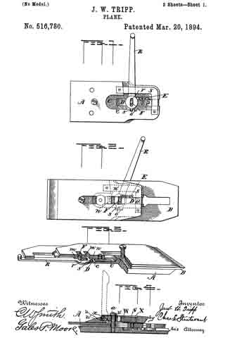
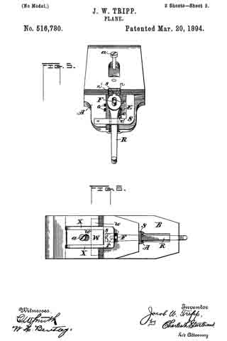
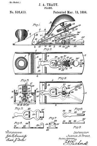
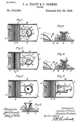
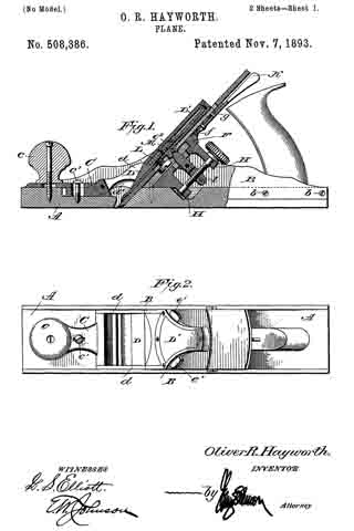
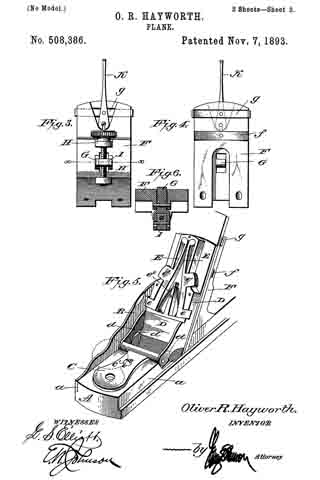
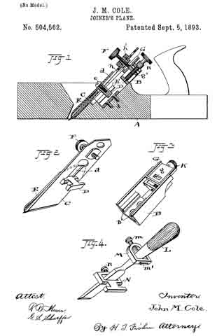
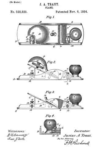
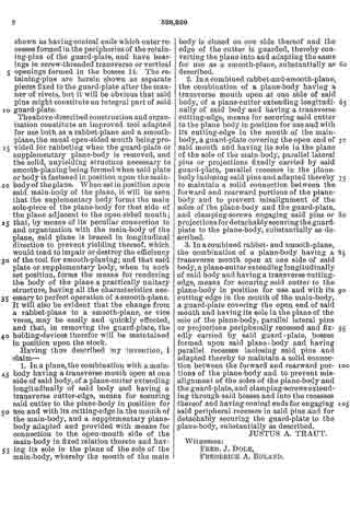
In the drawings accompanying and forming a part of this specification, Figure 1 is a plan view of a convertible plane embodying my invention, a portion thereof being broken away, the parts being assembled to adapt the plane for use as a smooth-plane. Fig. 2 is a side elevation of the same. Fig. 3 is a side elevation of a portion of the plane with the side-plate or guard-plate removed, the plane in this condition being adapted for use as a rabbet-plane. Fig. 4 is a vertical cross-section of the plane taken in dotted line a–a, Fig. 2, looking in the direction of the arrow in said figure.
Similar characters designate like parts in all of the figures.
In the drawings I have shown my invention applied to a plane, which in general construction and organization is similar to the ordinary metallic smooth-plane. The main body or rabbet-plane body, of the plane is designated in a general way by B, and consists of the usual base or sole, 3, divided transversely by the mouth 4, forming the front and rear portions 5 and 5′, and the side-walls 6 and 6’, the one 6′ of which is herein shown as divided vertically by the mouth 4, the base or sole 3 being preferably reinforced each side of the mouth 4 by the transverse ribs 7 and 7’. The main body is usually provided at the forward end thereof (shown in Figs. 1, 2 and 3 as the right hand end) with a knob or handle, 3.
The plane-iron or cutter C which may be supported in any usual manner from below, as shown in Figs. 2 and 3, and the clamp-lever D, are, or may be, of any usual construction and organization. The cutter C is shown in the drawings as having its cutting edge in the mouth of the main body and as supported upon a longitudinal rib, 9, having an inclined face coinciding with the inclined face of the reinforced portion 7 of the base, the upper face thereof being engaged by the cutting-edge, while the forward end of the clamp-lever is held in place longitudinally by a screw, 10, extending through the forward end of said lever, through an elongated slot formed in the cutter, and entering the reinforced portion 7’ of the base.
As a means for operating the clamp-lever to clamp the cutter, a screw, 11, is provided which has a screw-threaded bearing at its upper end in the rear end of the clamp-lever, and bears at its lower end upon the rear end of the cutter, said screw usually being provided, in practice, with a wheel or disk for operating the same. It is desired to state in this connection, that these elements just described, i. e. — the cutter and its clamping devices, constitute no part of my present invention, and may be of any usual construction and organization.
As a means for rendering the plane convertible, to adapt the same to be used either as a rabbet-plane or as a smooth-plane, I have provided a guard-plate or suplementary body, G, adapted to be detachably-secured to one side of the main-body so as to cover the open side of the plane and the open end of the mouth 4, and so that the lower edge of said plate will be flush with the bottom edge of said body to guard the cutter, as most clearly shown in Figs. 2 and 3. This plate or body constitutes a guard for the open end of the mouth 4, and when secured in place, as illustrated in Figs. 1 and 2, adapts the plane for use as a smooth-plane.
As a convenient means for detachably-securing the supplementary body or guard-plate to the side of the main-body, said plate is herein shown provided at opposite ends with laterally-projecting pins,12, adapted for entering holes, 13, drilled in bosses, 14, formed upon the base 3 of the main-body, as clearly shown in Figs. 1, 2 and 3, said plate being held against lateral displacement by means of set-screws, 15, extending through the bosses 14 and impinging the retaining-pins 12 of the guard-plate. These binding-screws are herein shown as having conical ends which enter recesses formed in the peripheries of the retaining-pins of the guard-plate, and have bearings in screw-threaded transverse or vertical openings formed in the bosses 14. The retaining-pins are herein shown as separate pieces fixed to the guard-plate after the manner of rivets, but it will be obvious that said pins might constitute an integral part of said guard-plate.
The above-described construction and organization constitute an improved tool adapted for use both as a rabbet-plane and a smooth-plane, the usual open-sided mouth being provided for rabbeting when the guard-plate or supplementary plane-body is removed, and the solid, unyielding structure necessary to smooth-planing being formed when said plate or body is fastened in position upon the main-body of the plane. When set in position upon said main-body of the plane, it will be seen that the suplementary body forms the main sole-piece of the plane-body for that side of the plane adjacent to the open-sided mouth; that, by means of its peculiar connection to and organization with the main-body of the plane, said plane is braced in longitudinal direction to prevent yielding thereof, which would tend to impair or destroy the efficiency of the tool for smooth-planing; and that said plate or supplementary body, when in such set position, forms the means for rendering the body of the plane a practically unitary structure, having all the characteristics necessary to perfect operation of a smooth-plane. It will also be evident that the change from a rabbet-plane to a smooth-plane, or vice versa, may be easily and quickly effected, and that, in removing the guard-plate, the holding-devices therefor will be maintained in position upon the stock.
Having thus described my invention, I claim —
1. In a plane, the combination with a main-body having a transverse mouth open at one side of said body, of a plane-cutter extending longitudinally of said body and having a transverse cutter-edge, means for securing said cutter to the plane-body in position for use and with its cutting-edge in the mouth of the main-body, and a supplementary plane-body adapted and provided with means for connection to the open-mouth side of the main-body in fixed relation thereto and having its sole in the plane of the sole of the main-body, whereby the mouth of the main body is closed on one side thereof and the edge of the cutter is guarded, thereby converting the plane into and adapting the same for use as a smooth-plane, substantially as described.
2. In a combined rabbet-and-smooth-plane, the combination of a plane-body having a transverse mouth open at one side of said body, of a plane-cutter extending longitudinally of said body and having a transverse cutting-edge, means for securing said cutter to the plane body in position for use and with its cutting-edge in the mouth of the main-body, a guard-plate covering the open end of said mouth and having its sole in the plane of the sole of the main-body, parallel lateral pins or projections fixedly carried by said guard-plate, parallel recesses in the plane-body inclosing said pins and adapted thereby to maintain a solid connection between the forward and rearward portions of the plane-body and to prevent misalignment of the soles of the plane-body and the guard-plate, and clamping-screws engaging said pins or projections for detachably securing the guard-plate to the plane-body, substantially as described.
3. In a combined rabbet and smooth-plane, the combination of a plane-body having a transverse mouth open at one side of said body, a plane-cutter extending longitudinally of said body and having a transverse cutting-edge, means for securing said cutter to the plane-body in position for use and with its cutting edge in the mouth of the main-body, a guard-plate covering the open end of said mouth and having its sole in the plane of the sole of the plane-body, parallel lateral pins or projections peripherally recessed and fixedly carried by said guard-plate, bosses formed upon said plane-body and having parallel recesses inclosing said pins and adapted thereby to maintain a solid connection between the forward and rearward portions of the plane-body and to prevent misalignment of the soles of the plane-body and the guard-plate, and clamping-screws extending through said bosses and into the recesses thereof and having conical ends for engaging said peripheral recesses in said pins and for detachably securing the guard-plate to the plane-body, substantially as described.
JUSTUS A. TRAUT.
Witnesses:
FRED. J. DOLE,
FREDERICK A. BOLAND.