No. 496,267 – Plane (Edward Maddox) (1893)

UNITED STATES PATENT OFFICE.
_________________
EDWARD MADDOX, OF VICTORIA, CANADA.
PLANE.
_________________
SPECIFICATION forming part of Letters Patent No. 496,267, dated April 25, 1893.
Application filed August 3, 1892. Serial No. 442,089. (No model.)
_________________
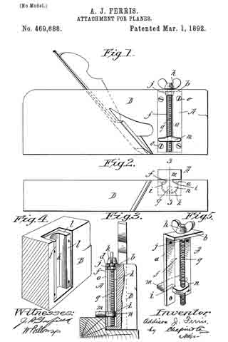
To all whom it may concern:
Be it known that I, EDWARD MADDOX, of Victoria, Canada, have invented certain new and useful Improvements in Planes; and I do hereby declare the following to be a full, clear, and exact description of the invention, such as will enable others skilled in the art to which it appertains to make and use the same.
This invention contemplates certain new and useful improvements in planes, and has for its object the production of a cheap, simple and highly efficient plane in which the cutting blade can be readily and easily adjusted and firmly held at any desired point.
The invention comprises a plane having its stock or body provided with an opening an adjustable cutting-blade, a screw in engagement with a threaded portion of said blade for effecting the adjustment thereof, a spring closing the rear portion of said opening and bearing on said blade, and a locking plate or lever having a short arm designed to bear upon and lock said spring, substantially as hereinafter fully set forth and particularly pointed out in the claims.
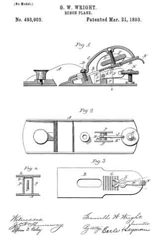
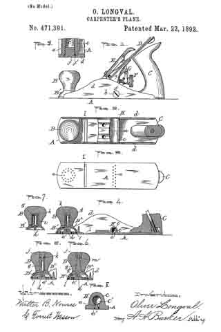
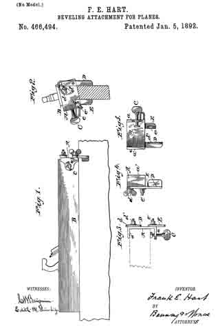
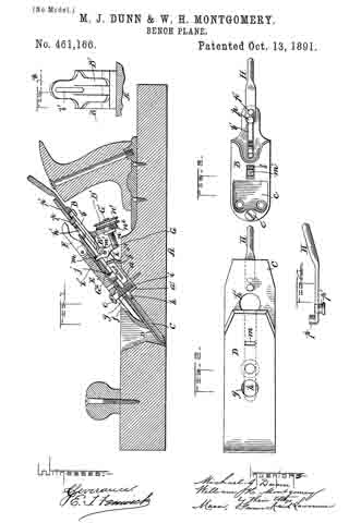
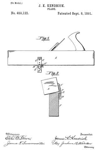
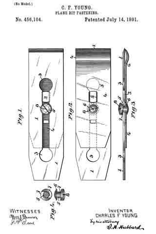
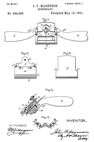
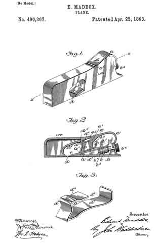
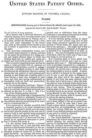
In the accompanying drawings: — Figure 1 is a view in perspective of my improved plane. Fig. 2 is a vertical longitudinal sectional view thereof, on the line x–x, Fig. 1. Fig. 3 is a view of the binding spring removed.
Referring to the drawings, A designates the stock or body which is preferably formed of metal and is hollowed or chambered; and a is the ordinary opening, terminating at its lower end in a transverse slot a’.
B is a screw-rod or spindle, provided with a threaded portion b, an inner reduced end b’, and a milled head b2, which is on the outer end of said spindle outside of the rear end of stock or body A, said spindle being projected through a hole or opening in said end. The forward reduced end b’ of screw-rod B is supported by an apertured cross-plate or partition b3 formed with stock A.
C is the cutting blade, having a forward widened cutting end d, and provided with grooves or disconnected threads d’ on the under side of its shank corresponding to the threaded portion of screw-rod B, which engages therewith. By turning this screw rod the cutting end of the blade can be made to project over or withdrawn from the transverse slot a’, according to the position to which it is desired to adjust the blade.
D is the binding spring, having an upper short arm d2 and a lower long arm d3, said arms being connected together by a curved portion d4 which closes the upper, rear portion of the opening a. The upper end of this connecting portion is designed to fit against a shoulder d5 of inclined wall d6 of stock or body A. The arm d2 is slightly bent or curved downward, while the lower arm d3 has a central bulge or curved portion d7.
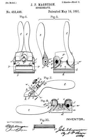
E is a locking plate or lever, which comprises a bent or curved arm e and an inner angular, short arm e’. This locking plate or lever is pivotally connected by a cross-pin e2 projected through stock A, between the sides of which the curved arm e snugly fits when the locking plate or lever is closed. A shoulder or off-set e3 is formed on the upper, inner end of arm e’, and the same is designed to engage the outer end of the upper arm of spring D and force the same upward, while the outer end of short arm e’, when the locking plate or lever is closed, binds firmly down upon the curved or bulged portion of the lower arm of said spring. Thus by means of the locking plate or lever the cutting blade can be firmly bound at any point, its adjustment being effected by the turning of the screw-rod when said locking plate is opened, so as to relieve the spring pressure.
The advantages of my invention are apparent to those skilled in the art to which it appertains. It will be seen that I have produced a plane which is simple; inexpensive; and free from all complications; and one in which the cutting blade can be readily adjusted to any desired position and firmly held at any point to which so adjusted.
I claim as my invention —
1. The herein-described improved plane, comprising the hollow stock or body having central opening, the cutting blade having grooves or disconnected threads in its under side, the inclined screw-rod located in and inclosed by said stock or body and having its spindle extended beyond said stock or body, the binding spring also inclosed by said stock or body and the locking plate or lever, pivotally secured to said stock or body and designed to engage and bind said spring, substantially as set forth.
2. The combination of the stock or body having a central opening, the adjustable cutting blade, and the binding spring bearing on said blade and having a curved portion inclosing the rear portion of said opening, substantially as set forth.
3. The herein-described improved plane, comprising the stock or body having a central opening, the cutting blade having threads, the rod or spindle having a threaded portion in engagement with said threads of the cutting blade, the spring closing the rear portion of said opening and having upper and lower curved arms, the latter bearing on said cutting blade, and the locking plate or lever fulcrumed between the sides of said stock or body and having its short arm provided with a shoulder or off-set designed to engage said upper arm of said spring, said arm at its lower end engaging said lower arm of said spring substantially as set forth.
4. The herein-described improved plane, comprising the stock or body having a central opening, the cutting blade, means for adjusting the same, the spring having upper and lower curved arms and a curved connecting portion designed to close the rear portion of said opening in the stock or body, and the locking plate or lever fulcrumed between the sides of said stock or body and having short arms designed to engage the arms of said spring and bind the latter, substantially as set forth.
In testimony whereof I have signed this specification in the presence of two subscribing witnesses.
EDWARD MADDOX.
Witnesses:
OAK P. MYERS,
GEORGE McCAULAY.