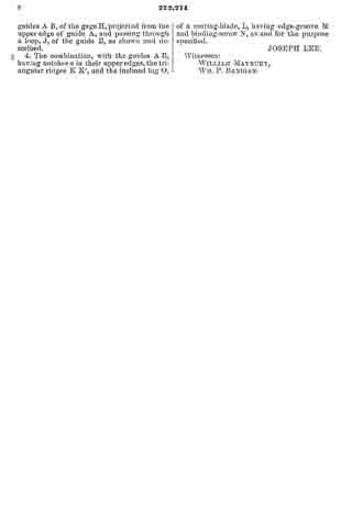
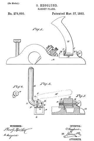
No. 274,600 – Rabbet-Plane (Oliver Hegglund) (1883)
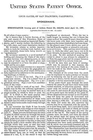
UNITED STATES PATENT OFFICE.
_________________
OLIVER HEGGLUND, OF OAKLAND, NEBRASKA.
RABBET-PLANE.
_________________
SPECIFICATION forming part of Letters Patent No. 274,600, dated March 27, 1883.
Application filed December 5, 1882. (No model.)
_________________
To all whom it may concern:
Be it known that I, OLIVER. HEGGLAND, of Oakland, in the county of Burt and State of Nebraska, have invented a new and useful Improvement in Rabbet-Planes, of which the following is a full, clear, and exact description.
This invention consists of a contrivance of the handle of a rabbet-plane for adjusting it into several different positions with relation to the plane, to adapt the plane for holding in different ways for different kinds of work, as hereinafter described.
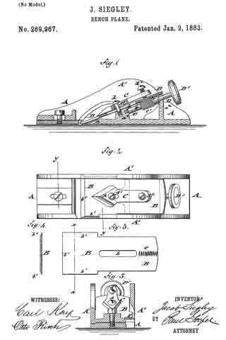
Reference is to he had to the accompanying drawings, forming a part of this specification, in which similar letters of reference indicate corresponding parts in all the figures.
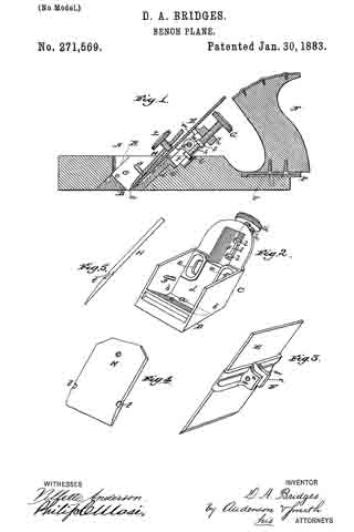
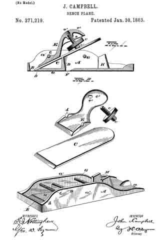
Figure 1 is a side elevation of a rabbet-plane with a handle applied according to my invention. Fig. 2 is an end elevation. Fig. 3 is a section of figures on line x x; and Fig. 4 is a perspective view of the nut employed, together with the binding-screw for securing the handle.
A represents the plane-stock, on the back end of which I attach the block B by screws a, so that it can be readily detached, said block having a recess, C, between ears D, wherein I pivot the handle E, as shown, on the binding-screw F, on which screw the handle can turn when not screwed up tight by the screw, the said screw being fitted in the ears D, and traversing the recess C, on which the handle is located, and screwing into a nut, H, in one of the ears in which said nut is fitted so as not to turn, so that it can draw up against the handle and bind it fast against the other ear.
K is a set-screw screwing into the recess from the back of the block and binding against the nut of the handle to secure it in any position in which it may be set. The handle is constructed with the bend L, for the purpose of enabling it to he turned over the back of the block B, as shown by the dotted lines in Fig. 2. The block B is detachably connected to the plane-stock, as before stated, for the purpose of detaching it and attaching a long straight handle projecting rearward of the plane-stock, and in line with it, when the plane is to be used for dressing deep mortises.
Having thus described my invention, I claim as new and desire to secure by Letters Patent —
1. In a rabbet or other plane, the combination, with the recessed block or support secured upon the rear end of the stock, of the pivoted handle having the bend L, the pivotal screw, and the holding or adjusting screw, substantially as and for the purpose set forth.
2. In a rabbet or other plane, the combination, with the recessed block or support secured upon the rear end of the stock, of the handle having its hub arranged in the recess of said block, against which hub bears a holding or set screw, the pivotal screw, and binding-nut, fitted to slide in one of the ears of the block and to bear against one end of the handle-hub, and adapted to be operated by the pivotal screw, substantially as and for the purpose set forth.
OLIVER HEGGLUND.
Witnesses:
JOHN GEDROW,
WALTER HEGGLUND.