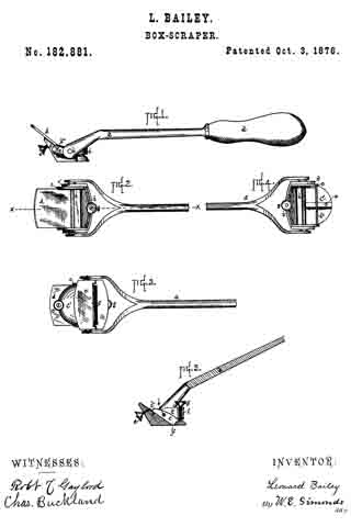
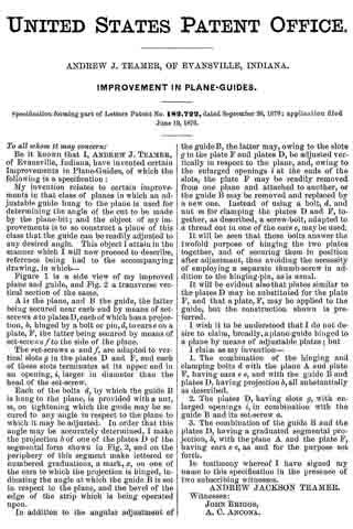
No. 184,241 – Improvement In Plane-Guides (William H. Harris And Milo Harris) (1876)

[paiddownloads id=”271″]184241


UNITED STATES PATENT OFFICE.

_________________

WILLIAM H. HARRIS AND MILO HARRIS, OF JAMESTOWN, N. Y.

IMPROVEMENT IN PLANE-GUIDES.

_________________

Specification forming part of Letters Patent No. 184,241, dated November 14, 1876; application filed July 3, 1876.

_________________

To all whom it may concern:

Be it known that we, WM. H. HARRIS and MILO HARRIS, of Jamestown, in the county of Chautauqua and State of New York, have invented certain new and useful Improvements in Plane Guides; and we do hereby declare that the following is a full, clear, and exact description thereof, which will enable others skilled in the art to which it appertains to make and use the same, reference being had to the accompanying drawings, and to the letters of reference marked thereon, which form a part of this specification.

The object of our invention is to furnish a cheap and simple guide for bench-planes, so as to plane or saw any desired bevel; and the nature of the invention consists in the combination of devices employed, as hereinafter more fully set forth.

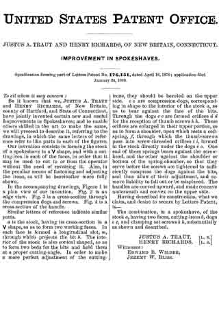
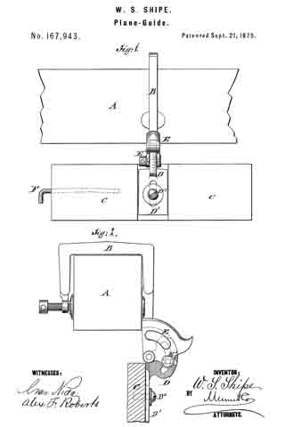
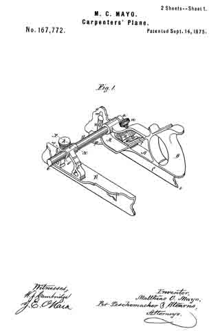
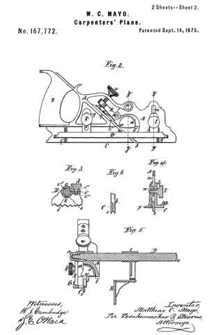
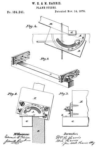
Figure 1 is a view of the guide, with a protractor and end plate attached to each end. Fig. 2 is a view of the metal plate attached to the end of a plane. Fig. 3 is a side view of the plane and guide, with end plate and protractor attached. Fig. 4 is a view of our invention as applied to a saw-table.

ln the drawings, A represents a semicircular bevel-protractor, made of suitable metal, and having a long circular slot near its center, through which the bolt or screw D passes to secure it firmly to the end plate B, and also a semicircular stud, x, at its lower edge, that turns in the semicircular indentures c c c, and also a lip turned at right angles with its surface, through which screws pass to securely fasten it to the guide C. B is a metal plate, that is securely fastened to the end of a plane, as shown in Fig. 2, and having screw-holes for this purpose, and holes a a a, with a screw-thread cut in them to receive the bolt D. It has also sernicircular indentures c c c in its lower edge to receive the stud x of the bevel-protractor. One of these plates, with the bevel-protractor, is fastened at each end of the plane, and, having the guide C attached, is shown in Figs. 1 and 2. The object of having so many places for the bolt D is that by so doing we can use any part of the face of the plane, and by changing ends with the guide C it will work on the back part of the plane-face, thus enabling us to bevel either edge of the board. The object of indentures c c c and stud x is to form a center for the bevel-protractor to turn on, in order that the corner of the guide C will always retain its relative position with the face of the plane, and as the bolt-holes a a a are placed at an angle of forty-five degrees with the indentures c c c we do not have to use but three indentures c c c for all the bolt-holes, no matter on which side of the plane-face the gage is used.

The plate B may be made with a long slot through its center, and a movable nut to receive the bolt D, or said plate may be made dovetailing, and inserted in a movable plate on which the bevel-protractor moves across the plane; but we prefer the manner shown in the drawings, as it is cheaper and more secure.

By means of the semicircular stud x in the bevel protractor A, and the indentures c c c in the metal plate B, the guide C can be moved to any part of the face of the plane, and the inner corner of said guideis held in the exact center of the circle described by the bevel-protractor A, and the guide is kept close to the face of the plane at any angle it maybe turned without any further adjustment, and by turning the lip d parallel with the face of the plane a much thinner guide can be used and thinner lumber planed without coming in contact with the work-bench.

We claim —

The combination of the bevel-protractor A, having stud x and lip d, with the end plate B, provided with the semicircular indentations c c c, the screw-bolt D, and the guide C, all constructed to operate as shown and described, and for the purpose specified.

In testimony that we claim the foregoing as our own invention we affix our signatures in presence of two witnesses.

WM. H. HARRIS.
MILO HARRIS.

Witnesses:
J. E. GOULD,
J. E. HARRIS.

No. 182,881 – Improvement In Box-Scrapers (Leonard Bailey) (1876)

[paiddownloads id=”270″]182881


UNITED STATES PATENT OFFICE.

_________________

LEONARD BAILEY, OF HARTFORD, CONNECTICUT.

IMPROVEMENT IN BOX-SCRAPERS.

_________________

Specification forming part of Letters Patent No. 182,881, dated October 3, 1876; application filed September 13, 1876.

_________________

To all whom it may concern:

Be it known that I, LEONARD BAILEY, of Hartford, in the county of Hartford and State of Connecticut, have invented certain new and useful Improvements pertaining to a Box-Scraper, of which the following is a specification, reference being had to the accompanying drawings, where —

Figure 1 is a side view. Fig. 2 is a top view. Fig. 3 is a bottom view. Fig. 4 is a top view, chisel removed. Fig. 5 is a central section on plane x x, Fig. 2, chisel removed.

The letter a denotes a forked handle, whereby to move the scraper back and forth. b denotes a rod, which is at once a pivot-bar for head c and a front rest for chisel d. The back side of the pivoted head c is obliqued, to form a bed for the chisel, which chisel is held in place by thumb-screw e running up through the bed elongation c’ from the back side, and bearing against the back side of the chisel.

The throat f may be made larger or smaller, and the out of the chisel correspondingly increased or decreased by manipulation of the guard or gage i, pivoted by its side arms i1 on the rod b, given a closing tendency by the spring-bar i2, and opened against this tendency by the thumb-screw g.

The features of invention, specified in the first two clauses of the following claim, are applicable as well to spokeshaves as to box-scrapers.

I claim as my invention —

1. In combination, head c, having bed elongation c’, chisel d, front rest b, and thumb-screw e passing through the bed elongation and pressing on the back side of the chisel, all substantially as shown and described.

2. In combination, bar b, head c, chisel d, guard or gage i pivoted on bar b, spring-bar i2, and screw g, all substantially as shown and described.

3. In combination, forked handle a, bar b, serving as pivot for head c and front rest for chisel d, pivoted head c having elongation c’, and screw e, all substantially as shown and described.

LEONARD BAILEY.

Witnesses:
ROBT. F. GAYLORD,
CHAS. BUCKLAND.

No. 182,722 – Improvement In Plane-Guides (Andrew J. Teamer) (1876)

[paiddownloads id=”269″]182722


UNITED STATES PATENT OFFICE.

_________________

ANDREW J. TEAMER, OF EVANSVILLE, INDIANA.

IMPROVEMENT IN PLANE-GUIDES.

_________________

Specification forming part of Letters Patent No. 182,722, dated September 26, 1876; application filed June 12, 1876.

_________________

To all whom it may concern:

Be it known that I, ANDREW J. TEAMER, of Evansville, Indiana, have invented certain Improvements in Plane-Guides, of which the following is a specification:

My invention relates to certain improvements in that class of planes in which an adjustable guide hung to the plane is used for determining the angle of the cut to be made by the plane-bit; and the object of my improvements is to so construct a plane of this class that the guide can be readily adjusted to any desired angle. This object l attain in the manner which I will now proceed to describe, reference being had to the accompanying drawing, in which —

Figure 1 is a side view of my improved plane and guide, and Fig. 2 a transverse vertical section of the same.

A is the plane, and B the guide, the latter being secured near each end by means of set-screws a to plates D, each of which has a projection, b, hinged by a bolt or pin, d, to ears e on a plate, F, the latter being secured by means of set-screws f to the side of the plane.

The set-screws a and f, are adapted to vertical slots g in the plates D and F, and each of these slots terminates at its upper end in an opening, i, larger in diameter than the head of the set-screw.

Each of the bolts d, by which the guide B is hung to the plane, is provided with a nut, m, on tightening which the guide may be secured to any angle in respect to the plane to which it may be adjusted. In order that this angle may be accurately determined, I make the projection b of one of the plates D of the segmental form shown in Fig. 2, and on the periphery of this segment make lettered or numbered graduations, a mark, x, on one of the ears to which the projection is hinged, indicating the angle at which the guide B is set in respect to the plane, and the bevel of the edge of the strip which is being operated upon.

In addition to the angular adjustment of the guide B, the latter may, owing to the slots g in the plate F and plates D, be adjusted vertically in respect to the plane, and, owing to the enlarged openings i at the ends of the slots, the plate F may be readily removed from one plane and attached to another, or the guide B may be removed and replaced by a new one. Instead of using a bolt, d, and nut m for clamping the plates D and F, together, as described, a screw-bolt, adapted to a thread out in one of the ears e, may be used.

It will be seen that these bolts answer the twofold purpose of hinging the two plates together, and of securing them in position after adjustment, thus avoiding the necessity of employing a separate thumb-screw in addition to the hinging-pin, as is usual.

It will be evident also that plates similar to the plates D may be substituted for the plate F, and that a plate, F, may be applied to the guide, but the construction shown is preferred.

I wish it to be understood that I do not desire to claim, broadly, a plane-guide hinged to a plane by means of adjustable plates; but I claim as my invention —

1. The combination of the hinging and clamping bolts d with the plane A and plate F, having ears e e, and with the guide B and plates D, having projection b, all substantially as described.

2. The plates D, having slots g, with enlarged openings i, in combination with the guide B and its set-screw a.

3. The combination of the guide B and the plates D, having a graduated segmental projection, b, with the plane A and the plate F, having ears e e, as and for the purpose set forth.

In testimony whereof I have signed my name to this specification in the presence of two subscribing witnesses.

ANDREW JACKSON TEAMER.

Witnesses:
JOHN BRIGGS,
A. C. ANCONA.

No. 182,320 – Improvement In Spokeshaves (George D. Mosher) (1876)

[paiddownloads id=”268″]182320


UNITED STATES PATENT OFFICE.

_________________

GEORGE D. MOSHER, OF NEW BRITAIN, CONNECTICUT.

IMPROVEMENT IN SPOKESHAVES.

_________________

Specification forming part of Letters Patent No. 182,320, dated September 19, 1876; application filed August 24, 1876.

_________________

To all whom it may concern:

Be it known that I, GEORGE D. MOSHER, of New Britain, in the county of Hartford and State of Connecticut, have invented certain new and useful Improvements pertaining to Spokeshaves, of which the following is a specification, reference being had to the accompanying drawings, where —

Figure 1 is a front view. Fig. 2 is a rear view. Fig. 3 is a sectional view on plane x x. Fig. 4 is a detail fron view of the clamp. Fig. 5 is a top view of same.

The letter a denotes the body of the spoke shave, mortised centrally for the passage of the knife b, which lies on the bed c. From the body a rises the standard d, and its front face is a prolongation of the knife-bed c. The knife is held to place by the clamp e, having a loop, e’, the loop of running around the back of the standard d. A set-screw, f runs through the front of clamp e, and bears on the knife.

The novelty consists in the means just described for holding the knife in place; and the same ideas are applicable to planes and box-scrapers.

I claim as my invention —

The combination of the knife b, the clamp e, having the loop e’, and the standard d, all substantially as described, and for the purpose set forth.

GEORGE D. MOSHER.

Witnesses:
WILLIAM H. MAIN,
CHAUNCEY BECKWITH.

No. 181,649 – Improvement In Plane-Irons (Henry Disston) (1876)

[paiddownloads id=”267″]181649


UNITED STATES PATENT OFFICE.

_________________

HENRY DISSTON, OF PHILADELPHIA, PENNSYLVANIA.

IMPROVEMENT IN PLANE-IRONS.

_________________

Specification forming part of Letters Patent No. 181,649, dated August 29, 1876; application filed April 29, 1876.

_________________

To all whom it may concern:

Be it known that I, HENRY DISSTON, of Philadelphia, Pennsylvania, have invented certain Improvements in Plane-Irons, of which the following is a specification:

The object of my invention is to so construct a plane-bit that it may be more readily and truly ground and sharpened than ordinary edge-tools of this class, a further object of my invention being economy in the consumption of material in making the tools.

In the accompanying drawing, Figure 1 represents a front view of a plane-bit made according to my invention; Fig. 2, a section on the line 1 2; Fig. 3, a transverse section on the line 3 4; Fig. 4, a modification of Fig. 3.

The plane-bit A (shown in Figs. 1, 2, and 3) has a series of parallel grooves or indentations, a, on that side from which the tool is beveled to a sharp edge, the grooves being of such a depth that they will extend into the beveled portion d, as shown. With the exception of these grooves or indentations the plane bit is similar to those of ordinary construction; and, as it is no thicker than usual, the ribs between the grooves impart the desired rigidity, While less material is consumed an its manufacture than in making common bits.

The grinding of the beveled edge of a bit thus constructed can be more readily accomplished than that of an ordinary bit, for the reason that there is less metal to remove, and it is much easier to grind truly an indented surface than one without grooves, as will be readily understood by those familiar with grinding operations.

The plane-bit can be readily manufactured by means of two dies, one being flat, for the flat face of the bit, the other having ribs corresponding with the desired indentations, and the two dies being used in connection with any ordinary drop press.

It is not essential that the indentations or grooves and intervening ribs should be of the precise shape shown in the sectional view, Fig. 3. They may, for instance, be of the form shown in Fig. 4, with good results as regards the facility of grinding, sharpening, and economizing of material.

I claim as my invention —

As a new article of manufacture, a plane-bit having grooves or indentations on its beveled side, as specified.

In testimony whereof I have signed my name to this speciiication in the presence of two subscribing witnesses.

HENRY DISSTON.

Witnesses:
A. H. SHOEMAKER,
GEO. S. GAUDY.

No. 180,867 – Improvement In Bench-Planes (Jackson Gorham) (1876)

[paiddownloads id=”266″]180867


UNITED STATES PATENT OFFICE.

_________________

JACKSON GORHAM, OF CRAWFORDVILLE, GEORGIA, ASSIGNOR TO HIMSELF AND CHARLES E. SMITH, OF SAME PLACE.

IMPROVEMENT IN BENCH-PLANES.

_________________

Specification forming part of Letters Patent No. 180,867, dated August 8, 1876; application filed July 11, 1876.

_________________

To all whom it may concern:

Be it known that I, JACKSON GORHAM, of Crawfordville, in the county of Taliaferro and State of Georgia, have invented an Improvement in Bench-Planes, of which the following is a specification:

My invention consists of a stud applied on the top of a smoothing-plane stock near the heel, and adapted to fit between the thumb and forefinger of the right hand, while the palm bears against the heel of the stock, whereby the pressure of the hand is distributed over a larger surface, and is thus diminished on the small area heretofore employed for driving the plane by pressing against the heel of the stock. It also affords a bearing or rest for a part of the hand not heretofore having any support on the stock, and therefore making the work easier.

The drawing is a perspective side elevation of a plane-stock constructed according to my invention.

A is the stock, and B the stud, which I apply as above described. The rear side of the stud a is made in suitable transverse convex; form and vertical concave form, to make an easy bearing for the hand. The handle may be made separate from the stock and attached to it, or it may be worked out of the block in connection with it.

Having thus described my invention, what I claim as new, and desire to secure by Letters Patent, is —

The plane-stock A, having the stud B, constructed in the form represented at a, and located relatively to the heel of the stock, substantially as specified.

JACKSON GORHAM.

Witnesses:
V. T. SMITH,
CHARLES A. BEAZLEY.

No. 180,050 – Improvement In Bench-Planes (William Montgomery) (1876)

[paiddownloads id=”265″]180050


UNITED STATES PATENT OFFICE.

_________________

WILLIAM MONTGOMERY, OF AMITY, PENNSYLVANIA.

IMPROVEMENT IN BENCH-PLANES.

_________________

Specification forming part of Letters Patent No. 180,050, dated July 18, 1876; application filed April 27, 1876.

_________________

To all whom it may concern:

Be it known that I, WILLIAM MONTGOMERY, of Amity, in the county of Washington and State of Pennstylvania, have invented Improvements in Bench-Planes; and I do hereby declare that the following is a full, clear, and exact description of the same, reference being had to the accompanying drawing, which forms part of this specification.

My invention relates to a new combination of devices for adjusting and clamping the blade or plane iron in the stock of the plane; and it consists in the combination of devices employed as hereinafter more fully set forth.

Figure 1 in the accompanying drawing, represents a vertical longitudinal section through my improved plane. Fig. 2 is a section through the plane irons and attachments thereof on the line x x. Fig. 3 is a top view of the bed-plate, to which the clamping-lever, which secures the irons in the plane-stock, is pivoted. Fig. 4 is a diagram illustrating the manner in which the grain of the wood runs in relation to the face of the plane.

A is the stock, which may be made of wood or metal. The said stock is thinner, measured vertically, at the rear end or heel than at the forward end, and at the rear end the stock is provided with a projection, p, which supports inpart the handle n. In cutting the plane-stock to the wedge form the grain of the wood is cut obliquely across, as shown in Fig. 4, in which the dotted lines represent the grain of the wood, and the line f f represents the face of the plane. The bed-plate B, shown in Fig. 3, and in section in Fig. 1, is attached to the top of the plane-stock A, at the back of the throat T of said stock, the attachment being made by screws x. The bed-plate B has at its front end lugs l, Fig. 3, to which is pivoted, by a screw-bolt, or in any other suitable manner, the bent lever L, the said bed-plate being cut away between the said lugs to make room for said lever L, and the tops of said lugs being rounded off, to allow the plane-irons i t to retreat far enough at the top to allow the insertion of a wedge under them at the bottom. The front part of the lever L passes down into the throat T of the plane, a recess, r, being formed in the back of said throat for the reception of the said front part of said lever, and the rear part of said lever passes backward over the top of the bed-plate, at the rear of the said throat T. In the rear part of said lever is fitted a thumb-screw, R, and in the front part of said lever is formed a dovetail-groove, g, shown in section in Fig. 2.

The head of the screw m, which holds the top iron on the cutting-iron of the plane, is made in the form of a frustum of a cone, and of dimensions to adapt it to the dovetail groove g in the front part of the lever L. The point of the thumb-screw R rests in a notched saddle, S, either on the handle h, the bed-plate B, or the plane-stock A, in various kinds of planes, and the said screw may fit a female screw in the rear end of the lever L, or it may fit the thread of a nut swiveled to the said lever. The half-handle h is formed in one piece with the bed-plate B, as shown in Fig. 1, when the plane-stock A is made of wood; but when the plane-stock is made of metal the bed-plate B may be dispensed with, and the lugs l of the same, and the handle h, may be cast in one piece with said stock. And when a jack-handle is used, it is attached to the stock, and not to the bed-plate B. Also, in long-faced planes the projection p, which supports the rear of the handle in short-faced planes, is omitted, there being space enough for the support of said handle without the projection. The cutting iron i and top iron t are fitted into the throat, as shown in Fig. 1, the top iron being held upon the cutting-iron by the screw m, which passes through the slot n, in the cutting-iron, and screws into the top iron in the usual manner.

The adjustment and clamping of the irons i and t are performed as follows: The top iron t is placed in its proper position on the cutting-iron i, and is fastened there by the screw m. The irons are then placed in the throat T of the stock A, the head of the screw in passing down into the groove g of the lever L. The screw R is then turned down, and, its point being prevented from advancing, the hinder part of the lever L is forced upward. This forces the lower part of the lever L downward and rearward, and draws backward and downward the screw m, the head of which is engaged in the groove g of the said lever, and the opposite end of which is engaged in the female screw of the top iron, t. The plane-irons are thus firmly pressed against the lower part of the throat of the plane-stock, and that part of the lever L in front of the pivot of said lever, which pressure securely clamps the irons in the plane-stock.

The head of the screw m might be made of proper form to engage a groove of rectangular cross-section in the lower part of the lever L; but I prefer the dovetail groove and the corresponding shape of head for the said screw, because this form gives a wedging action, which holds the irons powerfully without excessive strain on the thumb-screw R.

A cheap, easy-running, and durable plane is thus produced, in which the handle is brought down nearer the work than in planes heretofore used, and hence the muscular power of the operator is more efficiently applied.

I claim —

The combination of the stock A, having projection p, with the pivoted lever L, provided with a dovetail groove in its face, adjusting-screw R, notched saddle S, bed-plate and handle B h, and screw m, all constructed to operate as shown and described, and for the purpose specified.

WILLIAM MONTGOMERY.

Witnesses:
B. F. MONTGOMERY,
JAMES B. MONTGOMERY.

No. 179,494 – Improvement In Bench-Planes (John J. Tower) (1876)

[paiddownloads id=”264″]179494


UNITED STATES PATENT OFFICE.

_________________

JOHN J. TOWER, OF BROOKLYN, NEW YORK.

IMPROVEMENT IN BENCH-PLANES.

_________________

Specification forming part of Letters Patent No. 179,494, dated July 4, 1876; application filed May 29, 1876.

_________________

To all whom it may concern:

Be it known that I, JOHN J. TOWER, of Brooklyn, in the county of Kings and State of New York, have invented an Improvement in Metal Plane-Handles, of which the following is a specification:

Metal planes have heretofore been constructed with handles of wood, and also with globular knobs at the forward end of the plane.

My improvement relates to a hollow cast-metal handle, secured to the plane by dove-tailed projections, so that the connection is very strong and durable, and at the same time the handle is very light, and of a size and shape to be grasped by the hand.

The handle is represented in the drawing by a vertical seetion, Figure 1, horizontal section, Fig. 2, and cross-section, Fig. 3.

The handle a is of cast metal, preferably of iron. It is made hollow, so as to be as light as possible and maintain the requisite strength. The general shape of this handle is similar to those made of wood, and hence it is as convenient in use. In order to strengthen the lower part of the handle, and prevent the same being bent by the attachment to the plate b of the plane, I introduce the cross-bar c, cast with the rest of the handle. Dovetails that taper slightly are employed for fastening the base of the handle to the plane-stock. These dovetails are made by lips inside the base of the handle, as seen at e. The dove-tail block f upon the plane-stock b is shorter than the base of the plane-handle a, and the dovetail portions e do not extend the whole distance along the inner edges of the handle, so that the handle a can be put over the dove-tail-block f by slipping it from the back forward, and keeping the back edge down, in order that the handle may receive the dove-tail-block, and the parts tapering, the handle may be secured firmly by driving it forward upon the dovetail block. By this construction it is not necessary to have any opening at the forward part of the base of the handle, as such base sets down flat upon the plane-stock, and makes a neat, handsome, and durable connection, the dovetail not being visible.

This hollow cast-iron plane-handle may be plated or otherwise finished, and as the handle extends to the upper surface of the bottom of the plane, the hand of the operator can be as near to the surface of the wood as possible, so that the power can be exerted to good advantage.

I do not claim a plane with a hollow knob or handle with dovetail projections for holding the plane-iron to the stock, as this has been used; neither do I claim a hollow metal plane-handle.

I claim as my invention —

The metallic plane-handle cast hollow, with a cross-bar, c, and dovetail lips e extending a part of the distance along the inner portion of the base, in combination with the dovetail block f upon the stock of the plane, substantially as set forth.

Signed by me this 22d day of May, A. D. 1876.

JOHN J. TOWER.

Witnesses:
GEO. T. PINCKNEY,
CHAS. H. SMITH.

No. 178,256 – Improvement In Carpenters’ Planes (Samuel Williams) (1876)

[paiddownloads id=”263″]178256


UNITED STATES PATENT OFFICE.

_________________

SAMUEL WILLIAMS, OF COLUMBUS, OHIO.

IMPROVEMENT IN CARPENTERS’ PLANES.

_________________

Specification forming part of Letters Patent No. 178,256, dated June 6, 1876; application filed March 15, 1876.

_________________

To all whom it may concern:

Be it known that I, SAMUEL WILLIAMS, of Columbus, in the county of Franklin and State of Ohio, have invented certain new and useful Improvements in Carpenters’ Planes; and I do hereby declare that the following is a full, clear, and exact description thereof, which will enable others skilled in the art to which it appertains to make and use the same, reference being had to the accompanying drawings, and to the letters of reference marked thereon, which form a part of this specification.

In the accompanying drawings, Figure 1 is a side elevation of a plane with my improvement attached thereto. Fig. 2 is a vertical transverse section of the same on the line x x, Fig. 1. Fig. 3 is an end view, showing the motion of the guide in dotted line. Fig. 4 is a full-sized view of the clutch-bolt and thumb-screw. Fig. 5 shows a detached modification.

My invention consists of certain novel combinations and arrangements of devices for a simple and efficient bevel-guide for planes, the details of which will be fully understood by the following description:

ln the accompanying drawings, A is a plane-stock, with a groove, B, out in each side, to receive the adjustable slide C, which is cast in the same piece with the male part F of the hinge. This slide has a rib, c, which fits the groove B of the plane, in order to prevent the slide from swinging, and thus throwing the bevel-guide out of place. The guide D is attached to the hinge-piece E, which is very strong, and has a slot with broad bearing-sun faces, to grasp the male part F of the hinge, and hold the same firmly in place. This hinge has a central pivot, G, and a set-screw, H, which passes through the curved slot I, Fig. 2, in order to adjust the bevel-guide to any desired angle. A clutch-bolt, K, passes through the plane-stock A, as shown in Fig. 4, and has one end provided with the clutch K’, to grasp the slide C, while the other end is provided with a thumb-screw or nut, L, and washer, M, for fastening the guide to the plane.

The hinge may be graduated in an arc, so as to set the guide D at any desired angle, as is well understood.

Instead of the clutch- bolt K, an arched plate, N, with a set-screw, O, may be used; but I prefer the clutch-bolt shown in Fig. 4.

If necessary with long planes, two clutch-bolts and two hinges may be used to hold the guide more securely in place.

This guide is very simple, and yet strong and durable, and it is very convenient of adjustment, and may be easily changed from one side of the plane to the other, and thus enable the workman to plane cross-grained stuff, and also prevent the uneven wear of the bit.

Having thus described my invention, I claim —

The slide C, provided with the rib c, in combination with the bolt K, bevel-guide D, and plane-stock A, substantially as and for the purposes set forth.

In testimony that I claim the foregoing as my own I affix my signature in presence of two witnesses.

SAML. WILLIAMS.

Witnesses:
DANIEL BREED,
S. E. CARPENTER.

No. 176,152 – Improvement In Bench-Planes (Justus A. Traut And Henry Richards) (1876)

[paiddownloads id=”262″]176152


UNITED STATES PATENT OFFICE.

_________________

JUSTUS A. TRAUT AND HENRY RICHARDS, OF NEW BRITAIN, CONNECTICUT.

IMPROVEMENT IN BENCH-PLANES.

_________________

Specification forming part of Letters Patent No. 176,152, dated April 18, 1876; application filed December 27, 1875.

_________________

To all whom it may concern:

Be it known that we, JUSTUS A. TRAUT and HENRY RICHARDS, of New Britain, county of Hartford and State of Connecticut, have invented a certain new and useful Improvement in Bench-Planes; and to enable others skilled in the art to make and use the same, we will proceed to describe it, referring to the drawings, in which the saine letters indicate like parts in each of the figures.

The nature of this invention consists in the device for holding and adjusting the cutting-iron.

In the accompanying drawings, Figure 1 is a side view of a plane, having one side portion of the stock removed to show the incline brackets, upon which the cutting-iron is held, and the compound levers for adjusting the irons. Fig. 2 is a top view of the compound levers detached from the stock. Fig. 3 is a side view of the compound levers detached from the stock. Fig. 4 is an enlarged view of the adjustable stud by means of which the cut of the iron is regulated through the mouth of the plane by means of the compound levers and the rocking spindle.

The object of this invention is to cheapen the manufacture, and produce a simple, sure, and effective mode of adjusting and holding the irons in the desired condition.

a is the stock. b is the handle; c, the knob for steadying the plane. S is a fastening-pad, which bears upon the lower end or face of the iron, and takes bearings on the upper side against the pins t t, and is provided with a thumb-screw, u, by means of which the iron, when adjusted, is held firmly in place. This fastening-pad and all above described are now in common use. d represents inclined brackets, arranged a short distance apart each way from the center of the stock, and in diverging lines back from the mouth e of the plane, and form bearings for the cutting-irons. f is a rocking spindle, having a groove, g, and a lever, h. This rocking spindle with its lever it is secured by fulcrum-bearings between and near the upper end of the brackets d, while the wrist-pin i in the lower end of the lever h vibrates in an opening in one of the brackets d. j is a thumb-lever, having near its lower end an opening to receive the pin i, which is secured near the lower end of one of the brackets d by a screw, m, and with or without a friction-collar, m’, so that by raising or depressing the lever j by a thumb-pad, n, the required vibration or rotation of the rocking spindle having the groove g will be produced, to cause the movement of the iron up or down. o is a stud, having a tooth projection, o’, fitted to, and working in, the groove of the rocking spindle f This stud o is fitted to play in an opening, p, formed in the cutting-iron or cap-plate, so as to allow it to be adjusted to its proper position, and then secured by a nut, r. Thus it will be seen that by the use of the adjustable stud o its tooth can be readily adjusted, and firmly secured to a single or double iron from time to time, as it becomes worn or ground off from its cutting end, and when the tooth o’ is placed in the groove g of the rocking spindle f by the action of the compound levers h j up and down, the cutting-iron can be easily and accurately adjusted and firmly secured by the fastening-pad S in the common way.

What we claim, and desire to secure by Letters Patent, is —

The combination of the levers h j, rocking spindle f, having groove g and brackets d, with the stud o, having the tooth projection o’, substantially as shown and described.

JUSTUS A. TRAUT. [L. S.] HENRY RICHARDS. [L. S.]

Witnesses:
EDWARD B. WILDER,
JEREMY W. BLISS.

No. 176,151 – Improvement In Spokeshaves (Justus A. Traut And Henry Richards) (1876)

[paiddownloads id=”261″]176151


UNITED STATES PATENT OFFICE.

_________________

JUSTUS A. TRAUT AND HENRY RICHARDS, OF NEW BRITAIN, CONNECTICUT.

IMPROVEMENT IN SPOKESHAVES.

_________________

Specification forming part of Letters Patent No. 176,151, dated April 18, 1876; application filed January 24, 1876.

_________________

To all whom it may concern:

Be it known that we, JUSTUS A. TRAUT and HENRY RICHARDS, of New Britain, county of Hartford, and State of Connecticut, have jointly invented certain new and useful Improvements in Spokeshaves; and to enable others skilled in the art to make the same, we will proceed to describe it, referring to the drawings, in which the same letters of reference refer to like parts in each of the figures.

Our invention consists in forming the stock of a spokeshave in a V shape, and with a cutting-iron in each of the faces, in order that it may be used to cut to or from the operator without the need of reversing it. Also, in the peculiar means of fastening and adjusting the irons, as will be hereinafter more fully shown.

In the accompanying drawings, Figure 1 is a plan view of our invention. Fig. 2 is an edge view. Fig. 3 is a cross-section through the compression dogs and screws. Fig. 4 is a cross-section of the handle.

Similar letters of reference indicate similar parts.

a is the stock, having its cross-section in a V shape, so as to form two working faces. In each face is formed a longitudinal slot, m, through which projects the bit b. The interior of the stock is also conical shaped, so as to form two beds for the bits and hold them at a proper cutting-angle. In order to make a more perfect adjustment of the cutting-irons, they should be beveled on the upper side. c c are compression-dogs, corresponding in shape to the interior of the stock a, so as to bear against the face of the bits. Through the dogs c c are formed orifices d d for the reception of thumb screws h h. These orifices are enlarged in their upper portion, so as to form a shoulder, upon which rests a coil-spring, f through which the thumb-screws pass into screw-threaded orifices i i, formed in the stock directly under the dogs c c. One end of these springs bears against the screw-head, and the other against the shoulder or bottom of the spring-chamber, so that they serve before the screws are tightened to sufficiently compress the dogs against the bits, and thus allow of their adjustment, and remove liability to fall out or be misplaced. The handles are curved upward, and made concave underneath and convex on the upper side.

Having described its construction, what we claim, and desire to secure by Letters Patent, is —

The combination, in a spokeshave, of the stock a, having two faces, cutting-irons b, dogs c c, and clamping set-screws h h, substantially as shown and described.

JUSTUS A. TRAUT. [L. S.] HENRY RICHARDS. [L. S.]

Witnesses:
EDWARD B. WILDER,
JEREMY W. BLISS.

No. 175,758 – Improvement In Box-Scrapers (Henry Richards And Justus A. Traut) (1876)

[paiddownloads id=”260″]175758


UNITED STATES PATENT OFFICE.

_________________

HENRY RICHARDS AND JUSTUS A. TRAUT, OF NEW BRITAIN, CONNECTICUT.

IMPROVEMENT IN BOX-SCRAPERS.

_________________

Specification forming part of Letters Patent No. 175,758, dated April 4, 1876; application filed March 13, 1876.

_________________

To all whom it may concern:

Be it known that we, HENRY RICHARDS and JUSTUS A. TRAUT, of New Britain, in the county of Hartford and State of Connecticut, have invented certain new and useful Improvements in Box- Scrapers; and we do hereby declare the following to be a full, clear, and exact description of the invention, such as will enable others skilled in the art to which it pertains to make and use it, reference being had to the accompanying drawings, which form part of this specification.

The nature of our invention consists in the construction and arrangement of a box-scraper, which is fully illustrated in the accompanying drawing.

A represents the shank of the tool-scraper fastened in the handle B at one end, and at the other end the shank forms two prongs, A’ A’, between which the head C is pivoted. The head is perfectly smooth and flat, with two side flanges, C’ C’, on its upper side, to which the prongs A’ of the shank are pivoted. On the upper side of the head C at the front are formed two parallel inclined ribs or flanges, a a, upon which the knife D rests, the edge of the knife projecting through a slot, b, in the head somewhat in the same manner as the blade of a carpenter’s plane. Between the upper ends of the side flanges C’ of the head is pivoted a jaw, E, having a set-screw, G, passed through its upper end. This screw bears against the upper portion of the knife or blade D, forcing the lower portion of the jaw also against the same, and holding the blade firmly and securely against the ribs or flanges a. The blade can easily and quickly be adjusted as required, and also be taken out for sharpening.

It will be noticed that the head rocks or oscillates between the prongs A’, and thus the scraper adapts itself to any position of the box and operator.

We are aware that a pivoted handle has been applied to planes for the purpose of pushing them along, and this we disclaim. We pivot our handle to the head for the purpose of drawing the scraper along, and allowing the head to accommodate itself to different surfaces.

Having thus fully described our invention, what we claim as new, and desire to secure by Letters Patent, is —

In a box-scraper, the combination of the handle B, pivoted to the head C, jaw E, blade D, set-screw G, and suitable rests for the blade, substantially as shown and described.

In testimony that we claim the foregoing we have hereunto set our hands this 3d day of March, 1876.

HENRY RICHARDS.
JUSTUS A. TRAUT.

Witnesses:
JACOB RETZ,
E. L. GOODWIN.

No. 174,870 – Improvement In Carpenters’ Planes (Elliot G. Storke) (1876)

[paiddownloads id=”259″]174870


UNITED STATES PATENT OFFICE.

_________________

ELLIOT G. STORKE, OF AUBURN, NEW YORK.

IMPROVEMENT IN CARPENTERS’ PLANES.

_________________

Specification forming part of Letters Patent No. 174,870, dated March 14, 1876; application filed February 7, 1876.

_________________

To all whom it may concern:

Be it known that I, ELLIOT G. STORKE, of Auburn, in the State of New York, have invented certain new and useful Improvements in Carpenters’ Planes, of which the following is a specification:

The object of my invention is to provide a simple, easy, and exact method of adjusting the bits or cutters of carpenters’ planes.

Figure 1 is a longitudinal vertical central section of an ordinary metallic plane embodying my improvements. Fig. 2 is a perspective view of the same with the bit removed.

Similar letters refer to the same parts in the respective figures.

A is the bed-plate for the support of the bit. Near the transverse center thereof is placed the sliding plate B, running in ways cut in the said bed-plate, having in its upper face an oval recess, C, for the reception of the cap screw heads of double plane-irons. From the lower face of the said sliding plate projects the shank-nut D, so far below the bed-plate that when the screw E is passed through its lower end, on a line parallel with the pitch of the plane-iron, a large thumb-wheel, F, can be mounted upon the upper end thereof without colliding with the plane-iron above or the plane-body below. That thumb-wheel is supplied with six arms, H, equally spaced upon its hub, giving as many distinct and conveniently-located levers, by which the workman can easily revolve the said wheel and move the parts with which it is connected. From the lower face of the bed-plate A, and near its upper end, projects the shank-bearing for the adjusting-screw G, of the same length as the shank-nut D, and in line therewith. Through the lower end of the said shank-bearing passes the upper end of the screw E into the hub of the said thumb-wheel, the former being shouldered where it joins the inner face of the latter, and the wheel, being pinned to the screw, carries the latter with it. Now, by revolving the thumb-wheel in the shank-bearing G, the shank-nut D and the sliding plate B are raised or lowered at pleasure, giving to the cutters a corresponding movement, and securing any desired thickness of shaving.

It will be seen from the foregoing description that my invention consists, mainly, in devices by which plane-bits are adjusted by a single direct-acting screw, operating through the medium of the cap-plates of double irons. The two shanks or lugs D and G, the screw E and sliding plate B, and the thumb-wheel F, with its arms H, are the devices employed for this purpose.

By projecting those lugs far below the bed-plate A — that is to say, far enough to carry the axis of the thumb-wheel to the center, or thereabout, of the space between the plane-iron and plane-body — I am enabled to use upon the screw E a large thumb-wheel supplied with the lever-arms H, and I thus gain all the power necessary to move the bits easily by the single screw E. The arms H, lying both to the right and left of the plane-handle, are easily and conveniently operated by the workman, either by the thumb from the left, or the fingers from the right, or both conjointly, without removing the hand — a device possessing decided conveniences over the circular thumb-screw heads heretofore in use for the same purpose.

I am aware that screws have been applied directly to plane-irons for their adjustment, but not in that way to the cap-plates of double irons, nor to their screw-heads. In the latter application the maximum movement of the operating-screw is less than one-half inch, in the former fully two and one-half inches, and a special attachment must be made to the cutter in which to work the screw; but that application, so far as I am informed, has been abandoned for the lack of power to operate the bits, and in its stead various combinations of single levers, or levers and cams operated by screws, have been resorted to, the objection to which is the increased cost of construction, and the greater liability to derangements and backlash.

I am also aware that various devices for adjusting plane-bits have been applied to the cap-plates or cap-screw heads of double plane-irons, but none, it is believed, in which that adjustment has been effected by a single screw without other intermediate devices.

The simplicity, durability, and practical efficiency of the devices herein described will, it is believed, be clearly apparent, as well as their superiority to those hitherto employed for the same purpose.

Having described my invention, I shall state my claim as follows:

The direct-acting or adjusting screw, having a thumb-wheel formed with lever-arms, as described, in combination with the bed-plate, having an elongated shank-bearing, and the sliding socket-plate, having an elongated shank-nut, all substantially as and for the purposes shown and set forth.

In testimony whereof I have hereunto signed my name this 3d day of February, A. D. 1876.

ELLIOT G. STORKE.

Witnesses:
H. L. STORKE,
LEWIS L. SMITH.

No. 174,399 – Improvement In Spoke-Shaves (Albert A. Wood) (1876)

[paiddownloads id=”258″]174399


UNITED STATES PATENT OFFICE.

_________________

ALBERT A. WOOD, OF MANLIUS, NEW YORK.

IMPROVEMENT IN SPOKE-SHAVES.

_________________

Specification forming part of Letters Patent No. 174,399, dated March 7, 1876; application filed July 31, 1875.

_________________

To all whom it may concern:

Be it known that I, ALBERT A. WOOD, of Manlius, in the county of Onondaga and State of New York, have invented a new and useful Improvement in Spoke-Shaves; and I hereby declare the following to be such a full, clear, and exact description of the same as will enable others skilled in the art to which it pertains to construct the same, reference being had to the accompanying drawings, making a part of this specification, and to the letters of reference marked thereon, similar letters indicating corresponding parts in the different figures.

This invention relates to that class of spoke-shaves commonly used by wheelwrights and joiners, the object being to provide a ready means of adjustment for the cutting-bit, so as to enable it to take a cut of a different thickness without being released from its holding-screws and readjusted; and the invention consists in attaching the cutting-bit to an oscillating plate, which is adjusted by means of a thumb-screw and spring, as will be hereinafter fully set forth, and then specifically pointed out in the claim.

Figure 1 of the drawings is a perspective view of the device complete. Fig. 2 shows the throat of the shave with the bit and its carrying-plate removed. Fig. 3 represents the carrying-plate with grooves and recess for the reception of the spring.

The handle or stock A of the shave is made of metal, and is provided with a throat, B, for the reception of the cutting-bit. Within this throat are two longitudinal projections or ridges, a a, and a third elevation, b, upon which the springs g rests. The plate C, having two depressions, d d, at each side, rests upon the projections a a of the stock, within the throat, upon which it oscillates. It also has secured to it, by the screws e e, a cutting-bit, D. This plate is further provided with a recess, f in which is placed a spring, g, the whole of these parts being retained in their proper positions within the throat of the stock by a thumb-screw, h, which passes through the plate and into the stock.

In operating this tool, the plate C, having the spring g in its proper recess, may be placed within the throat of the stock, and the thumb-screw h inserted, and turned up until the plate finds a bearing upon the stock; the bit D is then placed in position, and secured to the plate G by the screws e e, it being so adjusted that its cutting-edge shall project slightly through the throat, so as to take the thinnest shaving which may at any time be required. In order to increase the bite of the tool, and cause it to cut thicker shavings, it is only necessary to turn the thumb-screw slightly backward, which will allow the spring to throw up the outer end of the plate, which, oscillating upon the projections a a, causes the bit to project to a greater distance from the face of the stock, and consequently to cut a shaving of greater thickness, thus avoiding the necessity of loosening and refastening the cutting-bit at each adjustment thereof.

Having thus described my invention, I claim as new, and desire to secure by Letters Patent, the following:

The adjusting-plate C, provided with the recess f and carrying the cutting-bit D, in combination with the stock A and spring g, substantially as and for the purpose specified.

In testimony that I claim the foregoing I have hereunto affixed my signature this 30th day of July, 1875.

ALBERT A. WOOD. [L. S.]

Witnesses:
N. E. ROBINSON,
GEORGE S. BALLOCH.

No. 173,984 – Improvement In Bench-Planes (George F. Mortensen) (1876)

[paiddownloads id=”257″]173984


UNITED STATES PATENT OFFICE.

_________________

GEORGE F. MORTENSEN, OF NEW YORK, N. Y.

IMPROVEMENT IN BENCH-PLANES.

_________________

Specification forming part of Letters Patent No. 173,984, dated February 22, 1876; application filed August 20, 1875.

_________________

To all whom it may concern:

Be it known that I, GEORGE F. MORTENSEN, of the city, county, and State of New York, have invented a new and useful lmprovement in Bench-Planes, which improvement is fully set forth in the following specification, reference being had to the accompanying drawing, in which —

Figure 1 represents a longitudinal section of my improvement. Fig. 2 is a reverse plan view thereof, partly in section. Fig. 3 is a view of the slotted cap.

Similar letters indicate corresponding parts.

My invention relates to improvements in bench-planes, and as to one of its features particularly — to planes whose “stock” is made of wood.

That part of my invention relating to wooden planes consists in combining, with the “sole” thereof, an adjustable shoe for the purpose of regulating the “mouth” containing the plane-iron, the said shoe being made adjustable both vertically and horizontally through the medium of set-screws and of slots, through which the screws pass.

In the drawing, the letter A designates the stock of my plane, and B is the sole. C is the adjustable shoe, which is preferably made of metal, and is let into a cavity, D, immediately in front of the mouth a. The said shoe C is subjected to the action of set-screws E, which extend vertically into or through the stock A, to which end the stock is provided with a protecting-plate, F. The set-screws E extend both in an upward or downward direction. When the set-screws extend in both directions, as shown in Fig. 1, the head of the single screw, in this example extending downward, is preferably concealed in a socket, G, while, in order to conceal the heads of the upwardly-extending screws, and to impart to the shoe C a smooth surface, a face-plate, H, is affixed to the shoe. This face-plate is removed in Fig. 2, in order to expose the set-screws.

The set-screws pass through slots b, which, in the example shown in Fig. 1, are formed in the shoe C; but, if desired, the slots may be formed in the protecting-plate F.

By means of the set-screws E I am enabled to adjust the shoe C vertically toward the cavity D, for the purpose of preserving its level with the sole B, when the latter is “corrected,” while by providing the sole or the protecting-plate F with slots b, and passing the set-screws through the slots, the shoe may be adjusted to different positions horizontally, and particularly with respect to the mouth at, which, as is well known, becomes enlarged when the plane is corrected, owing to the slope of the bed d of the plane-iron.

The plane-iron I is made of the usual form, with an upper and a lower section, connected together by a screw, J.

K designates a cap, which, together with an eccentric or cam lever, L, constitutes a clamp for fixing the plane-iron on the bed d. The cap K is provided with a slot, N, which has at one end a hole, O, (see Fig. 3,) equal in diameter to that of a stud, P, formed by the head of a screw, which is fastened to the bed d, so that by moving the cap K to such a position that the stud occupies the narrow part of the slot, the cap is rendered capable of tilting under the stud P.

The cam-lever L turns on a pivot, c, and is fastened on the upper end of the cap K.

When the cam-lever is turned to the position shown in the drawing, it bears on the upper portion of the top section of the plane-iron I, thereby raising the upper end of the cap K, while by the tilting of the cap thus occasioned its lower end is caused to bear on the corresponding portion of said top section of the plane-iron, and by this arrangement the iron may be readily adjusted and firmly held in any position.

The stock A of my plane is made in two divisions, Q, (or more than two, if required,)
which are connected together by side strips or cheeks R. By this construction of the stock, far greater strength is imparted to it than when made in a single piece, while the parts of the stock, moreover, being very readily put together, the whole can be furnished at a comparitively small cost.

What I claim as new, end desire to secure by Letters Patent, is —

The combination, with the stock of a bench-plane, of a, recessed shoe, C, with a, detachable face-plate, H, the set-screws E E E and slots b, all constructed to operate substantially as described.

In testimony that I claim the foregoing I have hereunto set my hand and seal this 17th day of August, 1875.

GEORGE F. MORTENSEN. [L. S.]

Witnesses:
E. F. KASTENHUBER,
FRANCIS FORBES.

No. 173,177 – Improvement In Bench-Planes (Josef Nicht) (1876)

[paiddownloads id=”256″]173177


UNITED STATES PATENT OFFICE.

_________________

JOSEF NICHT, OF AUBURN, NEW YORK.

IMPROVEMENT IN BENCH-PLANES.

_________________

Specification forming part of Letters Patent No. 173,177, dated February 8, 1876; application filed July 29, 1875.

_________________

To all whom it may concern:

Be it known that I, JOSEF NICHT, of Auburn, in the county of Cayuga and State of New York, have invented certain new and useful Improvements in Bench-Planes; and that the following is a full, clear, and exact description of the same, reference being had to the accompanying drawings making a part of this specification, in which —

Figure 1 represents a perspective view of my improved plane, with the plane-irons and fastening-cap removed. Fig. 2 represents a longitudinal vertical section through my improved plane. Fig. 3 represents a detached view of the mechanism employed for raising or lowering the plane-irons. Fig. 4 represents a perspective view ofthe cap overlying the plane-irons, showing its under side and connected wedge. Fig. 5 represents a modification of the same.

Similar letters of reference, where they occur, denote like parts in all the figures.

My invention relates to certain combinations of mechanisms used to set or adjust plane-irons from the exterior of the plane without separating the parts, and with great expedition and accuracy.

My invention relates also to the means by which the plane-irons can be moved laterally to adjust them in that direction, and also to the means by which the plane-irons are retained in position by means of a cap and wedge.

To enable others skilled in the art to make and use my invention, I will proceed to describe the same with reference to the drawings.

A represents the wooden stock of a plane, to which is attached, by means of the screw a, the plate B, that has formed on its under side bearings b for the shaft c, around which the geared segment and lever C revolve. The rear end of this lever C is slotted, so as to fit over a pin formed on one side of the nut d, that is raised or lowered by a screw-shaft, D, having a knob or thumb-piece, D’, upon its upper end, by which it may be readily operated to raise or lower the nut d, and correspondingly the rear end of the lever C. On the front of the lever C there is a geared segment, C’, that engages with the rack E. This rack is located in a groove, b’, cut out of the plate B, so as to furnish it with the bearings required for a free and steady motion up or down. This rack E has on its upper surface a central projection, e, and another at e’, either or both of which engage with the head of a screw, f that is centrally recessed for that purpose. This screw f is otherwise the one employed to connect the plane-iron F and its iron cap F’, so that by turning the screw-shaft D the plane-irons may be moved up or down at pleasure to adjust them, and when adjusted they are firmly held in that position. G is a metallic cap overlying the plane-irons. A slot, g, is cut through it, so as to allow the head of the screw h to pass through it and rest on its upper surface. Under the rear of this cap G there is a wedge, H, by which the cap may be raised at that point and pressed against the plane-irons at or near their lower ends to clamp them together. The wedge H is retained in connection with the cap G by grooves formed on the latter, and a bolt, i, that connects the two together. To the plate B and stock A is pivoted at a a lever, k, the rear end of which projects upward, so as to be readily operated from the exterior of the plane, it terminating in a knob, k’, by which it can be moved. The inner end of this lever k is bent up, as at l, and passes into the slot ordinarily cut in plane-irons F, so that the latter can be moved laterally to adjust said irons in that direction. Thus the vertical and lateral adjustments of the plane-irons may be instantly and very accurately made.

In Fig. 5 is shown a modification of the cap G, the slot g of Fig. 4 being dispensed with, and the hook m formed in its place, so as to engage under the head of a bolt, or any similar projection attached to the stock A of the plane.

I claim as my invention —

In combination with the plane-stock A, the longitudinally-slotted plane-iron F and the mechanism composed of the screw h and cap G, carrying, secured to it, the wedge H, for clamping said plane-iron to the plane, the lever k’, pivoted to the stock of the plane, and engaging with the slot of the plane-iron to adjust it laterally, all arranged substantially as shown and described.

JOSEF NICHT.

Witnesses:
HORACE T. COOK,
W. P. BEARDSLEY.

No. 168,431 – Improvement In Bench-Planes (Justus A. Traut And Henry Richards) (1875)

[paiddownloads id=”255″]168431


UNITED STATES PATENT OFFICE.

_________________

JUSTUS A. TRAUT AND HENRY RICHARDS, OF NEW BRITAIN, CONN.

IMPROVEMENT IN BENCH-PLANES.

_________________

Specification forming part of Letters Patent No. 168,431, dated October 5, 1875; application filed June 15, 1875.

_________________

To all whom it may concern:

Be it known that we, JUSTUS A. TRAUT and HENRY RICHARDS, both of New Britain, county of Hartford and State of Connecticut, have jointly invented certain new and useful Improvements in Bench-Planes; and to enable others skilled in the art to make the same we will proceed to describe them, referring to the drawings, in which the same letters indicate like parts in each of the figures.

In the accompanying drawings, Figure 1 is a side elevation. Fig. 2 is an end view taken from the front.

The object of the present invention is to produce a plane with a wrought-metal stock or shell of suitable shape and form to possess all the needed strength and stiffness at the points of greatest strain, and yet be neat and serviceable in all the details and particulars of its construction; and to this end it consists in swaging or stamping said stock or shell from a blank or sheet of wrought metal, properly cut so as to afford strong sides and stiff angles, and in combining therewith a suitable body or filling, all as will now be more fully and particularly set out and explained.

In the accompanying drawings the wrought-metal stock or shell is indicated by the letter a; the wooden portion or filling of the plane is marked by letter b. This metal stock or shell is made from or of a piece of wrought metal, which is first cut according to suitable pattern of proper shape and size.

When thus prepared the same is placed over a die, and forced or compressed into the desired shape by a drop-hammer or power-press, thereby easily producing the desired shapes with rigid corners or angles in the stock or shell.

It will be seen that we prepare this form that the metal on a line with the opening where the cutting-iron is inserted shall be sufficiently wide to make broad and strong sides, wide enough, when shaped as above described, to come nearly or quite to the top of the wood.

The filling of the plane may be fastened or secured thereto in any convenient or usual way. By giving this breadth of metal and this shape to the stock or shell in this manner, and attaching it to the filling as described, the parts may be firmly united, and all tendency of the metal to yield or spring is entirely obviated.

The process of manufacture is very easily carried out, and need not be described any more at length in order to be fully understood by persons skilled in this manufacture.

Hitherto planes have been made with a cast-metal stock or shell, and various shapes and forms of them have been so constructed; but, so far as we have any knowledge of the art, none of these show the particular features now considered novel.

Planes have also been made having iron or steel soles, with flange edges sufficiently high to afford space to fasten them to the wooden sides of the plane; but we do not claim any such.

Having thus described our invention, what we consider new, and desire to secure by Letters Patent, is —

The combination of the wrought-metal stock or shell a, having two broad and strong sides, a a’, with a suitable filling, b, substantially in the manner and for the purposes set forth.

JUSTUS A. TRAUT.
HENRY RICHARDS.

Witnesses:
R. R. BLISS,
JEREMY W. BLISS.

No. 167,943 – Improvement In Plane-Guides (Walter S. Shipe) (1875)

[paiddownloads id=”254″]167943


UNITED STATES PATENT OFFICE.

_________________

WALTER S. SHIPE, OF MINERVA, OHIO.

IMPROVEMENT IN PLANE-GUIDES.

_________________

Specification forming part of Letters Patent No. 167,943, dated September 21, 1875; application filed August 14, 1875.

_________________

To all whom it may concern:

Be it known that I, WALTER S. SHIPE, of Minerva, in the county of Stark and State of Ohio, have invented an Improvement in Plane-Guides, of which the following is a specification:

In the accompanying drawing, Figure 1 represents an end view of my improved plane-guide, and Fig. 2 a side view of the same.

Similar letters of reference indicate corresponding parts.

My invention has for its object to so improve the plane-guide for which a patent has been granted to me under date of January 6, 1874, and numbered 146,208, that it will work more steadily and accurately, and be readily set to any desired angle.

The invention consists, mainly, of a recessed handle-extension of the yoke part in connection with a slotted arc-piece of the guide-strip connecting plate, the arc-piece being pivoted to the yoke, and set by a clamp-screw thereto. A wire key with bent end is inserted into a hole of the guide-strip for being readily available for turning the clamping-screw nuts.

In the drawing, A represents a plane, to which the yoke B is attached in the customary manner by a clamping-screw at one end, and flanged side extensions at the opposite end. The yoke B is cast at the end below the flanges with a handle-extension, E, that is centrally recessed tor the slotted arc-piece D, which forms, with its guide-plate D1, the connection with the guide-strip C. The slotted arc D extends at right angles from guide-plate D1, and is inserted and pivoted at its center in the handle-extension E. A set-screw, E’, passes through the perforations of the handle E and the slot of the arc-piece for the purpose adjusting the sliding arc to any required angle. The outer circumference of the arc-piece D is graduated, so that the same may be directly set with the guide-strip C to any required degree of inclination toward the plane. The guide-plate D1 is slotted and adjusted in a recess of the guide-strip C, nearer to, or farther from, the plane by a set-screw, D2. A key, F, of strong wire, with bent end is inserted into a socket-hole of guide-strip C, being slightly curved at its longer part to be retained there in with a certain tension without falling out, the shorter bent end serving as handle to withdraw it from the guide-strip. The wire key F is inserted into perforations of the heads of the set-screws, so that they can be easily loosened or tightened, while the key may be securely put away into the socket-hole of the guide-strip without getting lost. The key is thus always at hand tor use for setting the plane-guide, which is steadily and firmly adjusted in the handle-extension or socket-piece of the yoke.

Having thus described my invention, I claim as new and desire to secure by Letters Patent —

The combination, with a guide-strip, C, of plane-clamping yoke B, having recessed extension E, the pivotted slotted arc-piece D, and the clamp-screw E’, as and for the purpose specified.

WALTER S. SHIPE.

Witnesses:
JOHN BREIDENSTEIN,
A. N. BOORY.

No. 167,772 – Improvement In Carpenters’ Planes (Matthias C. Mayo) (1875)

[paiddownloads id=”253″]167772


UNITED STATES PATENT OFFICE.

_________________

MATTHIAS C. MAYO, OF BOSTON , MASSACHUSETTS, ASSIGNOR TO J.
GARDNER WELD, OF SAME PLACE.

IMPROVEMENT IN CARPENTERS’ PLANES.

_________________

Specification forming part of Letters Patent No. 167,772, dated September 14, 1875; application filed July 14, 1875.

_________________

To all whom it may concern:

Be it known that I, MATTHIAS C. MAYO, of Boston, in the county of Suffolk and State of Massachusetts, have invented certain Improvements in Carpenters’ Planes, of which the following is a full, clear, and exact description, reference being had to the accompanying drawings, making part of this specification, in which —

Figure 1 is a perspective view of a plane constructed in accordance with my invention. Fig. 2 is a side elevation of the same. Fig. 3 is a longitudinal vertical section on the line x x of Fig. 1. Fig. 4 is a transverse section on the line y y of Fig. 2. Fig. 5 is a transverse vertical section on the line z z of Fig. 2 ; Fig. 6, sectional detail.

My invention relates to that class of metallic planes for which Letters Patent of the United States were granted to Russell Phillips, August 13, 1867.

In these planes the adjustable gage which regulates the distance of the cutter from the edge of the work is supported upon a horizontal arm and secured, when adjusted, by a thumb-screw, the lower end of which enters a longitudinal groove or channel on the upper side of the arm.

This construction is, however, objectionable, as the point of the screw soon becomes worn, so that the gage cannot be securely confined upon the arm, and the tool becomes shaky; furthermore, the sides of the groove in the arm are liable to be indented by the screw, a ragged edge being thus produced, which interferes with the free movement of the gage.

The first part of my invention has for its object to remedy these difliculties; and consists in providing the sliding gage with a clamping device, which embraces the horizontal arm, and slides thereon with a spline or feather, by which construction any shifting of the gage, while the tool is being used, is effectually prevented.

My invention also consists in the peculiar construction of the gage by which the depth of the cut is regulated, this gage extending the entire or the greater portion of the length of the tool, and being provided with a clamping-screw near each end, the plate to which it is secured having a graduated scale at or near each end, by which means the tool is held perfectly level, and prevented from being tipped up at one end, as is liable to occur when the gage is placed just in front of the cutter, as heretofore, and the formation of a groove or out of equal depth throughout its entire length is thus insured.

My invention also consists in constructing the bottom plate of the plane with a lip or flange instead of with a square edge, as heretofore, the curvature of this lip corresponding to that of a portion of the edge of a bead-cutter of any size, the lip or flange serving as a guide for the cutter as soon as it begins to act, causing it to cut more gradually and smoothly than heretofore, and with less expenditure of power, thus forming a more perfect bead, while the narrow edge of the lip or flange admits of the formation of a wide bead with a narrow “quirk” or fillet, which it has not heretofore been possible to do with any tool made to cut beads of different widths.

My invention also consists in the peculiar construction of the lower end of the pivoted clamping-lever, which holds the cutter in place, whereby the clogging of the throat is effectually prevented.

To enable others skilled in the art to understand and use my invention, I will proceed to describe the manner in which I have carried it out.

In the said drawings, A represents the stock of the plane, which is formed of metal; B, the handle; and C, the bottom or sword plate. From one side of the stock A projects a horizontal arm or beam, D, which is held firmly in place by means of a screw-nut, a. Upon this arm D slides the metallic gage E, by adjusting the position of which the distance of the cutter b from the edge of the work may be regulated, as desired.

The gage is provided with a bracket, E’, supporting at its upper end a clamp, c, formed with a bearing, c’, and spline e, adapted to receive and embrace the longitudinal arm D. The upper portion of the clamp c, at c”, is cut through and provided with an extension, c”’, through which a tightening-screw, d, passes and engages with a corresponding extension, c””, formed on the bracket E’ and lower portion of the clamp-beaning c.

The gage is prevented from turning on the arm by the feather e on the arm D, which fits into a groove, f formed in the under side of the clamp; and by this device the gage is held rigidly upon the arm, and all liability of its position being changed while the tool is in use is effectually prevented; furthermore, when the screw d is loosened the gage E is always free to slide upon the arm D, which is not the case where the clamping-screw enters a groove in the arm, as heretofore.

The depth of the cut is regulated by an elongated gage, G, which is placed on one side of the plate C, and extends nearly its entire length.

From this gage project two vertical plates, g h, the plate g having a slot, i, through which passes a clamping-screw, k, and the plate h being provided with a clamping-screw, l, which passes through a slot, m, in the stock, and enters a slide, n, on the opposite side thereof, this slide having at its bottom a horizontal plate, P, which also serves as a gage, and, in connection with the gage G, effectually prevents the plane from being rocked laterally while in use, which would cause the opposite sides of the groove being cut to be of unequal depth; and, by means of the screws k l, the gages G P can be readily secured at any desired distance from the bottom of the plate G, so as to determine the degree of penetration of the cutter into the wood, the adjustment of the gage G being greatly facilitated by a graduated scale, q, near each end of the plate C.

By the employment of an elongated gage, G, extending the entire, or nearly the entire, length of the plate C, instead of a short gage placed just in front of the cutter, as heretofore, the operator is enabled to hold the tool perfectly level, and all liability of its being tipped up at one end, as was liable to occur with the old construction, is entirely avoided, and the formation of a groove or cut of equal depth throughout its entire length is thus insured.

The gage E is provided with a recess, r, for the reception of the gage P, which would otherwise prevent the gage E from being brought up as close to the plate C as might be desired.

The bottom of the plate C, instead of being made with a square edge, as heretofore, is formed with a projecting lip or flange, s, the curvature of which corresponds to that of a portion of the edge of a bead-cutter when secured in place, as seen in Fig. 6.

When a cutter of this description is employed, it is secured so as to project out on the inner side only of the plate G, as seen in Fig. 6, the cutting-points of the iron extending slightly below the bottom of the lip s, which thus serves as a guide for the cutter as soon as it commences to act, and also prevents the cutter from being forced deeply into the wood, as heretofore, which produces a rough and ragged edge, and the bead is thus caused to be cut gradually and smoothly and more perfectly than heretofore, and with less expenditure of power.

Any sized bead-cutter may be employed, and it will be seen that the narrow edge of the lip s will admit of the formation of a wide bead with a narrow quirk or fillet, which has heretofore been impracticable with any tool made to cut beads of various widths.

The cutter or iron b, which may be of any size or description desired, its into an inclined way, t, made to receive it, and is securely held by a clamping-lever, H, pivoted at 10 to the stock A.

Passing through the upper end of this lever is a thumb-screw, u, the lower end of which bears against the enlarged outer end of a spring-plate, v, secured to the under side of the lever, this plate, as the screw is turned, being brought down onto the upper end of the cutter, the further turning of the screw causing the lever H to be rocked in such manner as to bring its straight edge w firmly down upon the cutter at or near its center, the cutter being still further steadied in place by a groove in its under side, which fits over the edge 12 at the bottom of the way t.

The lever H thus admits of a cutter of any width or thickness being readily secured in place, while the enlarged end of the spring-plate v affords an extended bearing, so that the pressure of the screw may be exerted upon the entire width of the cutter.

The lower end of the lever H is provided with a concave or spoon-shaped enlargement, a’, arranged in such manner that it will receive the shavings as they issue through the throat b’ from the cutter b, and conduct the same sidewise clear of the upper surface of the throat, thereby effectually preventing any clogging of the throat by reason of the shavings accumulating above the same, as is the case with planes constructed in the usual manner.

On the side of each cutter is a pin, c’, by which it may be readily inserted, removed, or adjusted.

When the gage E and arm D are removed, which can be easily done, the plane can be ured as a dado, groover, rabbet, bead, V, or round plane, by merely inserting a cutter of the desired shape.

What I claim as my invention, and desire to secure by Letters Patent, is —

1. The divided clamp c, provided with bearing c’, slot f, and clamping-screw d, adapted to hold and embrace the arm D of a stock, A, substantially as shown and described.

2. The combination, with the sword-plate C, provided with a lip or flange, s, of the cutter b, pivoted clamping-lever H, provided with concave enlargement a’ and adjustable gage E, substantially as shown and described.

Witness my hand this 6th day of July, A.D. 1875.

MATTHIAS O. MAYO

In presence of —
N. W. STEARNS,
P. E. TESCHEMACHER.

No. 148,649 – Improvement In Metallic Bench-Planes (John A. Baines) (1874)

[paiddownloads id=”227″]148649


UNITED STATES PATENT OFFICE.

_________________

JOHN A. BAINES, OF NEW YORK, N. Y.

IMPROVEMENT IN METALLIC BENCH-PLANES.

_________________

Specification forming part of Letters Patent No. 148,649, dated March 17, 1874; application filed February 9, 1874.

_________________

To all whom it may concern:

Be it known that I, JOHN A. BAINES, of New York city, in the county of New York and in the State of New York, have invented certain new and useful Improvements in Metallic Bench-Planes; and do hereby declare that the following is a full, clear, and exact description thereof, reference being had to the accompanying drawings making a part of this specification, in which —

Figure 1 is a perspective view of the main frame, side gage, and sole or base plates of my plane. Fig. 2 is a plan view of the lower side of said frame. Fig. 3 is a perspective view of the detachable block or frame used for forming the smoothing and filletster planes. Fig. 4 is a plan view of the lower side of the same. Fig. 5 is a perspective view of the bottom gage. Fig. 6 is a like view of the detachable block employed for forming the sash-plane. Fig. 7 is a perspective view of the smoothing-plane complete. Fig. 8 is a plan view of the lower side of the same. Fig. 9 is a vertical section upon line x x of Fig. 8. Fig. 10 is a side elevation of the filletster-plane. Fig. 11 is a plan view of the lower side of the same. Fig. 12 is a plan view of the lower side of the tonguing-plane. Figs. 13 and 14 are, respectively, side and front elevations of the same. Fig. 15 is a plan view of the lower side of the grooving-plane. Figs. 16 and 17 are, respectively, a front and a side elevation of said plane. Fig. 18 is a plan view of the lower side of the sash-plane. Fig. 19 is a front elevation of the same. Fig. 20 is a section of said plane on line z z of Fig. 18, the cutting-tools being arranged for forming the meeting rail. Fig. 21 is a plan view of the lower side of a bead or round plane. Figs. 22 and 23 are, respectively, a side and a front elevation of the same. Fig. 24. is a front elevation of a hollow plane. Fig. 25 is a perspective view of a plow-plane. Fig. 26 is a plan view of the lower side of the same. Fig. 27 is a like view of a plane for forming center-beads. Fig. 23 is a front elevation of the same; and Fig. 29 is a side view of the cutting-irons employed, showing the shape of the cutting-edge of the same.

Letters of like name and kind refer to like parts in each of the figures.

The design of my invention is to lessen the cost and reduce the bulk of planes for producing irregular work; and to this end it consists in the construction and combination of the frame and various attachments employed for forming the different styles of plane, substantially as and for the purpose hereinafter specified.

In the annexed drawings, A represents the main frame of my tool, which has a plain lower surface, and at its upper side has such conformation as to enable it to receive the usual form of cutting-irons with the fastening-wedge, to permit the upward passage of shavings, and to provide for the attachment of a handle, B. Within the lower side, and near one edge of the frame A, is formed a narrow groove, C, which extends vertically upward within an enlargement or rib, A’, provided for the purpose, has a line parallel to the side of said frame, and receives two plates, D and D’, (shown in Fig. 1,) that form the base or sole. Two or more removable pins, d and d, pass horizontally and laterally inward through the side of said frame A, and through each of said plates D and D’, and locks the latter securely in position, when desired. Upon the inner side of the name A is formed a vertical groove, a, that receives the standard e of an adjustable gage, E, which gage is secured to or upon said frame, and held in vertical position by means of a screw, F, that passes into a threaded opening in the latter through a vertical slot in said standard.

Within the upper side of the frame A, near its ends, are formed two transverse grooves, g and g, that receive the ends of two corresponding bars, G and G’, which bars, when in position, are fastened by means of a screw, H, as shown in the front bar, or a pin, H’, as seen in the rear bar, said screw or pin being passed vertically downward through said bars into said frame. From the frame A the bars G and G’ extend laterally outward, and have their lower sides upon a line with the lower face of the former, in which position they form an extension of said face, and permit of the attachment of an angle-plate, I, (shown in Fig. 5,) which plate, being adjustable laterally toward or from the cutting-irons, forms a gage for several forms of plane. Within the lower side of the frame A, at or near its longitudinal center, is formed a transverse slot, a’; in rear of the same is provided a longitudinal slot, a”; while in front of the throat A” is a second longitudinal slot, a”’, the object of which is to enable the attachment of various parts required for forming several of the planes, said parts being described in connection with each plane of which it forms a part.

For use as a smoothing-plane, a hollow block, K, having the general form shown in Fig. 3, is placed upon the lower side of the main frame, and secured in posiuon by means of its inner side k, which extends upward into the groove C, and is provided with suitable openings k’ for the passage of the pins d and d.

The bolt k” of an adjustable throat-piece, k”’, projects upward through slots in said block and main frame and furnishes an additional means for securing said parts together.

The block K is provided with a throat, k””, which coincides with the throat of the main frame, and enables a cutting-iron, of usual form to be inserted and secured in place by means of the ordinary wedge.

To construct a filletster, the inner end of the throat k”” of the block K is uncovered by the removal of a covering plate or cap, K’, and the gage I attached to the lower face and outer side of said block, suitable threaded openings k””’ being provided within said block, for the reception of the binding-screws I’ of said gage.

The gage E is also placed in position and adjusted to depth, and, in connection with said gage I, enables the dimensions of the fillet or rabbet to be determined with certainty.

For use as a tonguing (matching) plane, the plates D and D’ are placed in position, the gage I attached to the lower face of the frame A, and upon the face of said gage is attached two blocks, L and L’, which have the form shown in Fig. 5, and perform the double office of a support for the heel of the inner half of the cutting-iron, and a gage for the depth of its cut. The gage E is also em-
ployed, its office being to insure the correct depth of cut for the outer half of said cutting-iron.

For a grooving-plane, the blocks L and L’ are removed, the gage I is moved inward to the position required by the thickness of the board, and a single cutting-tool inserted in place of the double one before used. The gage E is now reversed, so as to cause its bearing-face to extend inward nearly to the cutting-iron, the arrangement of parts being as shown in Figs. 15 and 16.

For use as a sash-plane, the plates D and D’ and the gages E and I are removed, and a block, M, having the form shown in Figs. 6 and 20, secured upon the lower side of the frame A by means of a screw, m, which extends upward through the longitudinal slot a” in said frame, and a second screw, m’, that passes downward through the transverse slot a”’ near the front end of said frame, and has its threaded end contained within a corresponding opening provided in said block. The blocks L and L’ are now attached to the inner face of the block M, where they serve as supports and gages for the cutting-iron that forms within the sash-rail the rabbet for containing glass, while the cutter for forming the molding upon said sash-rail is placed within a suitable throat formed in and through the molded face of said block M.

For use in forming the meeting rail, the gage-blocks L and L’ are removed, and the cutter shown in Fig. 20 inserted in place of that before employed for forming the glass rabbet.

For use as a beading or rounding plane, the block M is removed and a block, N, having the transverse shape shown in Fig. 23, is secured in its place upon the frame A, the size and shape of the groove it within the lower face of said blocks N and the corresponding features of the cutting-iron being varied to suit the especial purpose for which the tool is required.

To form a hollow plane, the shape of the lower face of the block N and of the edge of the cutting-iron are reversed, as shown in Fig. 24.

For use as a plow, the plates D and D’ are placed within the groove C, and the adjustable gage I secured upon the lower face of the frame A, or upon the extension–bars G and G’, after which the usual form of cutting-iron is inserted within the space between said plates, its heel resting upon the forward end of the rear plate D.

To form a center-bead plane, the extension-bars G and G’ and gage I are employed as before, the plates D and D’ are removed, and a hollow block, O, having the transverse form shown in Fig. 28, secured upon the lower face of the frame A. A cutting-iron having its lower or cutting end formed upon a line which corresponds to the grooved face of said block is placed in position within the throat o of the same, after which the plane is used in the ordinary manner.

As seen in Fig. 29, the lower end and forward side of such plane-irons as usually require caps are beveled off at an angle of about forty-five degrees with said side, so as to render more obtuse the angle of the cutting-edge, and enable any kind of wood to be cut smoothly and with ease without the use of a cap, by which means a saving is effected in the cost of said cutting-irons, and in the time and labor required in manipulating the planes.

The device thus constructed combines, in a simple and compact form, a number of tools which are usually separate, and enables them to be furnished at a comparatively small cost.

Having thus fully set forth the nature and merits of my invention, what I claim as new is —

The hereinbefore-described plane, constructed in the manner and for the purpose substantially as specified.

In testimony that I claim the foregoing, I have hereunto set my hand this 6th day of February, 1874.

JOHN A. BAINES.

Witnesses:
JOHN R. YOUNG,
JAS. E. HUTCHINSON.