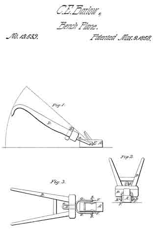
No. 269,968 – Bench Plane (Jacob Siegley) (1883)

[paiddownloads id=”62″]269968


UNITED STATES PATENT OFFICE.

_________________

JACOB SIEGLEY, OF NEW YORK, N. Y.

BENCH-PLANE.

_________________

SPECIFICATION forming part of Letters Patent No. 269,968, dated January 2, 1883.
Application filed May 22, 1882.

_________________

To all whom it may concern:

Be it known that I, JACOB SIEGLEY, of the city, county, and State of New York, have invented certain new and useful Improvements in Bench-Planes, of which the following is a specifcation.

This invention has reference to certain improvements in bench-planes, for which Letters Patent of the United States have been granted to me heretofore, which Letters Patent bear date, respectively, July 1,1879, and August 16, 1881, and are numbered 216,979 and 245,752, the improvements being designed with a view to lock the cutting-tool or plow in a more reliable manner and facilitate the forward feeding and adjusting of the same.

The invention consists of a bench-plane, the stock of which is provided with an inclined cutting-tool or plow, the upper surface of which is laterally grooved or serrated, to be engaged by a wedge-shaped locking-block having a correspondingly-grooved bottom, said block being secured against an inclined cheek of the stock by a lateral screw-post and clamp-nut, and moved forward by a longitudinal set-screw of the wedge shaped block, so as to raise or lower the plow in the stock.

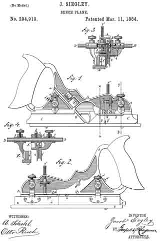
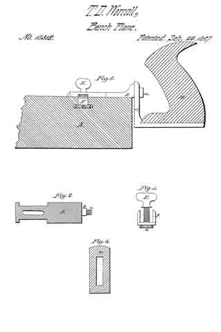
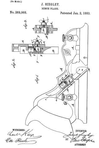
In the accompanying drawings, Figure 1 represents a side elevation of my improved bench-plane, and Figs. 2 and 3 are respectively a detail section on line x x, Fig. 1, and a vertical transverse section on line y y, Fig. 2.

Similar letters of reference indicate corresponding parts.

Referring to the drawings, A represents the stock of my improved bench-plane, which is made of cast-iron or other suitable metal, and with a handle of the usual form at the rear end. The middle part of the stock A is provided with an inclined recess, a, the lower surface of which forms the bearing-surface for the detachable plow or other cutting-tool B. The cutting-tool B is provided at its upper surface and near its middle portion with transverse grooves b b, which are engaged by the grooved or serrated bottom of a wedge-shaped locking-block, B’, the tapering top and side of which are guided along flaring cheeks d d of the stock A. The wedge-shaped block B’ is adjusted by means of a lateral screw-post, e, that is secured to the block and passed through a recess of the stock A, the block being tightly clamped to the stock and cutting-tool by a screw-nut, e’, as shown, respectively, in Figs. 2 and 3. The wedge-shaped block B’ is further arranged with a set-screw, j, that engages an interiorly-threaded socket of the wedge-shaped block B’, the set-screw f being arranged parallel to the cutting-tool or plow B, and provided with a head, f’, having socket-holes for inserting a suitable lever-pin, whereby the screw may be turned in one or the other direction. The head f’ of the screw f bears against a shoulder, f2, of the stock A, so that on turning the head the wedge-shaped block B’, and consequently the cutting-tool or plow B, is set higher or lower in the stock, as required for the proper setting of the tool. The wedge-shaped block B’ has to be of somewhat less length than the distance between the flaring front cheek, d, and the shoulder f2, so as to provide a certain play for the adjustment of the block and cutting-tool after the same has been placed in position in the recess of the stock. For adjusting the cutting-tool B the clamping-nut is first loosened and the cutting-tool adjusted so that its cutting-edge projects below the bottom surface of the stock A. The locking-block B’ is now clamped tightly to the grooved portion of the cutting-tool B, and, finally, the tool adjusted forward or back by means of the adjusting set-screw f so that the proper length projects below the bottom surface of the stock. In this manner a reliable locking device tor the cutting-tools of bench-planes is obtained, and a means whereby the cutting-tool may be accurately adjusted from time to time, as required by the work and the gradual wear of the tool.

Having thus described my invention, I claim as new and desire to secure by Letters Patent —

1. In a bench-plane, the combination of a stock having flaring cheeks, a plow or cutting-tool having transverse grooves at its upper surface, a wedge-shaped locking-block having a grooved bottom, means for clamping the block tightly to the cutting-tool. and means for longitudinally adjusting the locking-block and cutting-tool, substantially as and for the purpose set forth.

2. In a bench-plane, the combination of the stock: A, having an inclined recess, a, flaring cheeks d d2, and shoulder f2, a plow or cutting-tool, B, having transverse grooves b b, a, wedge shaped locking-block, B’, having a grooved bottom, a, lateral screw-post, e, and clamp-nut e’, and a longitudinal set-screw, f’, all substantially set forth.

In testimony that I claim the foregoing as my invention I have signed my name in presence of two subscribing witnesses.

JACOB SIEGLEY

Witnesses:
PAUL GOEPEL,
SIDNEY MANN.

No. 294,919 – Bench Plane (Jacob Siegley) (1884)

[paiddownloads id=”63″]294919


UNITED STATES PATENT OFFICE.

_________________

JACOB SIEGLEY, OF WILKES-BARRE, PENNSYLVANIA.

BENCH-PLANE.

_________________

SPECIFICATION forming part of Letters Patent No. 294,919, dated March 11, 1884.
Application filed July 6, 1883. (No model.)

_________________

To all whom it may concern:

Be it known that I, JACOB SIEGLEY, of Wilkes-Barré, Luzerne county, and State of Pennsylvania, have invented certain new and useful Iinproveinents in Bench-Planes, of which the following is a specification.

This invention has reference to certain improvements in bench-planes for which Letters Patent have been granted to me heretofore, which Letters Patent bear date. respectively, July 1, 1879, August 16, 1881, and January 2, 1888, and are numbered 216,979, 245,752, and 269,988, the improvements being designed with a view to cheapen the manufacture, increase the usefulness of the plane, and facilitate the handling of the same.

The invention consists of a bench-plane in which the fixed and movable blades are provided with advance cutters, which are inserted into sidewise-inclined perforations of said blades, and secured thereto by clamp-screws, so that the lower ends of the advance cutters project somewhat beyond the planes of the blades. The stock of the blade is provided with sockets cast integral therewith, for the purpose of receiving lateral guide-rods, which are made of one piece and clamped in said sockets by means of set-screws. The front part of the stock has a horizontal slot for the purpose of receiving the rim of a screw-nut, which engages the threaded shank of a stop-gage, said shank being guided in suitable holes arranged in the stock, while the stop-gage is guided in a recess of the laterally-adustable cage or fence.

In the accompanying drawings, Figures 1 and 2 are side views, showing both sides of my improved plane. Fig. 3 is a vertical transverse section on line x x, Fig. 1. Fig. 4 is a similar section on line y y of the same figure.

Similar letters of reference indicate corresponding parts.

Referring to the drawings, A represents the stock of my improved bench-plane, which is made of cast-iron or other suitable metal, and provided with a handle of the usual form at the rear end. The middle part of the stock A is provided with an inclined recess, a, in which a cutting tool or plow, B, of any required width is guided and locked in any approved manner, preferably by the means shown in Letters Patent No. 269,968, dated January 2, 1883. Along the lower part of the stock is arranged a fixed blade, C, while a second movable blade, C’, is arranged sidewise of and parallel to the fixed blade C, as will be shown hereinafter. Each of these blades C and C’ contains a laterally-inclined perforation that extends from the upper to the lower part of each blade, so that the lower end of the perforation opens partly at the outer side and partly at the bottom of its respective blade, as shown in Figs. 1 and 8. The advance cutters g and g’ are attached into said perforations by means of set-screws it It in such a manner that the cutting-edge of each cutter projects slightly at the side and lower edge ofthe blades C and C’, thereby providing a better clearance in the work for the plow. The stock A is provided at its front and rear part with openings and sockets A A’, that project at both sides of the same, for the purpose of receiving the guide-rods D and D’, which are made of one continuous piece and of the same thickness throughout, and secured in said sockets by means of set-screws d d’. Larger and smaller guide-rods D D are furnished with each plane, so as to adjust the movable blade C’ at one side and a fence, E, at the other side of the stock, to a greater or smaller distance from the same. On one side of the stock these guide-rods pass through the sleeves r and r’, which are cast in one piece with the blade C’, and secured by means of set-screws s s’. The sleeves and the blade C’ can be adjusted to various distances from the blade C, according to the width of the plow B. At the opposite sides of the stock A the guide-rods D D’ pass through sleeves t t’‘, which are attached to the gage or fence E. The sleeves t t’ are provided with set-screws u u’, for the purpose of laterally adjusting the gage E as the nature of the work may require. A horizontal slot, a2, is cut in the front part of the stock A, for the purpose of receiving the rim of the screw-nut F, which engages the threaded shank F’ of a stop-gage, F2, so as to raise or lower the same on turning the serew-nut F in one or the opposite direction. The shank F’ is guided in suitable holes arranged in the flanged stock A. The stop-gage F2 can thus be adjusted by means of its screw-shank and nut to any desired depth. The blade C’ is also furnished with a stop-gage, f, that is guided in a socket and secured by means of a setscrew, f’. The gage or fence E is provided with a, recess, i, for the stop-gage F2, so as not to interfere with the same, even when the gage E is placed close to the blade C of the stock A.

Having thus described my invention, I claim as new and desire to secure by Letters Patent —

1. In a bench-plane, the combination of the fixed and adjustable blades C C’, each having a laterally-inclined perforation, with advance cutters g g’ and clamp-screws h h’, the advance cutters projecting at their lower ends slightly beyond the outer side plane of the blades C C’, substantially as set forth.

2. In a bench-plane, the combination of the stock A, having a horizontal slot, a2, at its front part, a stop-gage, F2 the threaded shank of which is guided holes of the stock, and a screw-nut, F, the rim of which is engaged by the slot a2, so that the screw-nut F raises or lowers the stop-gage on being turned in one or the opposite direction, substantially as described.

3. In a bench-plane, the combination of the stock A., having a horizontal slot at its front part, a stop-gage, F2, the threaded shank of
which is guided in holes of the stock, an adjusting screw-nut, F, the rim of which is engaged by the slot a2, and a gage or fence, E, having a side recess, i, for the stop-gage F2 substantially as set forth.

In testimony I claim the foregoing as my invention I have signed my name in presence of two subscribing witnesses.

JACOB SIEGLEY.

Witnesses:
CARL KARP,
SIDNEY MANN.

No. 446,194 – Bench Plane (Jacob Siegley) (1891)

[paiddownloads id=”64″]446194


UNITED STATES PATENT OFFICE.

_________________

JACOB SIEGLEY, OF WILKES-BARRE, PENNSYLVANIA.

BENCH-PLANE.

_________________

SPECIFICATON forming part of Letters Patent No. 446,194, dated February 10, 1891.
Application filed May 23, 1890. Serial No. 352,944. (No model.)

_________________

To all whom it may concern:

Be it known that I, JACOB SIEGLEY, of Wilkes-Barre, in the county of Luzerne and State of Pennsylvania, a citizen of the United States, have invented certain new and useful Improvements in Bench-Planes, of which the following is a specidcation.

This invention relates to certain improvements in the bench-plane for which Letters Patent No. 294,919 were granted to me heretofore under date of March 11, 1884, said improvements being designed with a view to simplify the adjustment and the clamping of the cutting tool or bit to the stock and to perrmit the quick and convenient adjustment of the bit.

The invention consists of a bench-plane in which the cutting tool or bit is rigidly fastened to the stock by a clamping-block having transverse steel edges that are pressed against the bit by a thumb-screw acting on the top of the block. The steel block is provided with a longitudinal top groove and guided by said groove on a fixed steel plate attached to the stock, so as to permit the adjustment of the clamping-block by a threaded shank turning in recesses of the stock and by a nut located in an opening of the stock, as will be more fully described hereinafter, and finally pointed out in the claims.

In the accompanying drawings, Figure 1 represents a side elevation of my improved bench-plane. Fig. 2 is a vertical transverse section on the line 1 1, Fig. 1; and Figs. 3 and 4 are respectively a side elevation and a top view of the steel block for clamping the bit of the plane, said block and its adjusting screw-nut being drawn as detached from the stock.

Similar letters of reference indicate corresponding parts.

Referring to the drawings, A represents the stock of my improved bench-plane, which stock is made of cast-iron or other suitable metal, and provided with a handle of the usual form at the rear end. The middle part of the stock is provided with an inclined recess a, in which the cutting tool or bit B is guided and locked in position by means of a steel block C, which is provided in its bottom facing the bit with transverse hardened-steel edges d d, that are pressed firmly against the bit by a wing-screw D, and hold it thereby securely in its place in the stock A. The top of the steel block C is provided with a longitndinal slot e, which is engaged by a steel plate e’, that is attached to the recessed side of the stock A by means of fastening-screws e2. The steel plate e’ serves for holding the steel block in position and guiding it in its up-and-down motion when it is adjusted with the bit. After the bit is adjusted the wing-screw D, which passes through the stock at right angles to the clamping-block C, is tightly applied to the block so as to clamp the same and the bit B firmly to the stock.

The steel block C is provided with a threaded shank f, which is located in recesses f’ of the stock and engaged by a screw-nut f2, having a milled rim, said screw-nut extending transversely through an opening f3 of the stock A and being retained in position therein by the adjacent portions of the stock. On turning the screw-nut f2 in one or the opposite direction the steel block C is moved up or down and carries the bit along so as to adjust the same in proper position in the stock. After the adjustment is made the wing-screw D is tightly applied to the steel block e’, so that the same clamps the bit firmly and securely in position.

My improved fastening and adjusting device for the bit permits the quick adjustment and reliable clamping of the same without necessitating the slotting or recessing of the bit for applying the adjusting device.

Having thus described my invention, I claim as new and desire to secure by Letters Patent —

1. The combination, with the stock, of a bench-plane, said stock having an inclined recess, a cutting tool or bit in said recess, a clamping-block having hardened edges bearing on said bit, and means for adjusting said steel block and bit, substantially as set forth.

2. The combination, with a stock having an inclined recess, of a cutting tool or bit seated in said recess, a clamping-block having hardened edges bearing on said bit, a wing-screw pressing on the top of the block for clamping it to the bit, and means for adjusting said block and bit, substantially as set forth.

3. The combination, with a stock having an inclined recess, of a cutting tool or bit seated in said recess, a clamping-block having hardened edges at the bottom and a longitudinal guide-groove in its top, a steel plate attached to the stock and extending into said top groove, a wing-screw pressing in the top of the block for clamping the same to the bit, and means for adjusting the steel block and bit, substantially as set forth.

4. The combination, with a stock; having an inclined recess, of a cutting tool or bit seated in said recess, a clamping-block having transverse hardened edges at its bottom and a longitudinal groove in its top part, a fixed guide-plate extending into said groove, a threaded shank attached to the clamping-block and set into recesses of the stock, and an adjusting screw-nut engaging said shank and located in an opening of the stock, substantially as set forth.

In testimony that I claim the foregoing as my invention I have signed my name in presence of two subscribing witnesses.

JACOB SIEGLEY.

Witnesses:
HENRY JACKSON,
C. W. KULP.

No. 165,355 – Improvement In Tonguing And Grooving Planes (Charles G. Miller) (1875)

[paiddownloads id=”57″]165355


UNITED STATES PATENT OFFICE.

_________________

CHARLES G. MILLER, OF NEW BRITAIN, CONNECTICUT, ASSIGNOR TO THE STANLEY RULE AND LEVEL COMPANY, OF SAME PLACE.

IMPROVEMENT IN TONGUING AND GROOVING PLANES.

_________________

Specification forming part of Letters Patent No. 165,355, dated July 6, 1875; application filed April 9, 1875.

_________________

To all whom it may concern:

Be it known that I, CHARLES G. MILLER, of New Britain, in the county of Hartford and State of Connecticut, have invented an Improvement in Tonguing and Grooving Planes, of which the following is a description and specification, reference being had to the accompanying drawings, where —

Figure 1 is a side view of a plane embodying my invention, the view showing that side of the tool upon which the shifting guide, hereinafter described, is hung. The tool is adjusted as a tonguing-plane. The view from this side is, however, precisely the same when the tool is adjusted as a grooving-plane. Fig. 2 is a front-end view of the tool adjusted as a tonguing-plane, showing the pivot, on which the shifting guide is hung, in central vertical section. Fig. 3 is a front-end view of the tool adjusted as a grooving-plane.

This invention is a device which is, at pleasure, a plane for tonguing the edges of boards, or a plane for grooving the edges cf boards to receive such tongues. It is a tool for use in making what is known to carpenters as “matched stuff,” and combines in itself both a tonguing and a grooving tool.

The invention consists in a shifting guide, which can be adjusted so as to leave both the knives or chisels uncovered, making a tonguing-plane of the tool; or it can be adjusted to cover one of the chisels or knives, making a grooving-plane.

The letter a denotes the metallic stock or body of the tool; b, the handle, and c the throat, down which runs what carpenters call the “iron” d, forked at its lower end into the two chisels d1 d2, which do the cutting. e denotes the wedge which holds the iron in place. The letter f denotes the shifting guide, eccentrically attached to the shaft i, hung and rotating in the socket g, attached to the stock a. The pin i1 runs into the top of the shaft or trunnion i, and forms, practically, a part thereof. The spring m, bearing between the shoulders g1 i2, presses the guide f constantly upward. In either adjustment, for tonguing or for grooving, the guide f is held to position by the pins n, (shown in dotted lines,) which project downward from the fingers o, which project side-wise from the stock a, three teats entering corresponding holes in the top of the guide f.

When the operator desires to shift the adjustment of the guide f, he presses downward upon the top of the pin i1 till the guide clears the pins n, when it can be readily rotated upon its pivot in the socket g from one adjustment to the other.

In place of the vertical movement allowed, by this construction and arrangement, to the guide f, I contemplate depriving the guide of this vertical play, and in place thereof make one of the pins n, or both of them, a spring-catch.

When the guide f is adjusted as shown in Fig. 2, both the chisels d1 d2 are left uncovered for work, and the tool forms a tonguing-plane. When the guide f is adjusted as shown in Fig. 3, one of the chisels is covered, and the tool forms a grooving-plane; and these differences of adjustment are due to the fact that the guide f is hung eccentrically upon its pivot.

I claim as my invention —

ln combination with the body or stock a and the chisels d1 d2, the guide f, having adjustments to cover and uncover one of the chisels, substantially as shown and described.

CHARLES G. MILLER.

Witnesses:
FRED. N. STANLEY,
T. A. CONKLIN.

No. 142,037 – Improvement In Match Planes (Charles G. Miller) (1873)

[paiddownloads id=”1″]13957


UNITED STATES PATENT OFFICE.

_________________

CHARLES G. MILLER, OF NEW BRITAIN, CONNECTICUT, ASSIGNOR TO OLIVER S. JUDD AND CHARLES BLAKESLEE, OF SAME PLACE.

IMPROVEMENT IN MATCH-PLANES.

_________________

Specification forming part of Letters Patent No. 13,957, dated December 18, 1855.

_________________

To all whom it may concern:

Be it known that I, CHARLES G. MILLER, of New Britain, in the county of Hartford and State of Connecticut, have invented a Combined Tonguing and Grooving Plane, of which the following is a specification, reference being had to the accompanying drawings, in which —

Figure 1 is a side view of the implement. Fig. 2 is an end view of the forward end of the same — the end A. Fig. 3 is a flat view of the under side of the iron.

The plane or tool to which this invention appertains is made of cast metal ; and the invention consists in making an arch to span the cross-cut in which the plane-iron lies, so as to support both ends of the tool, which arch, at the same time, forms a part of the handle of the plane, and forms a back or buttress for the adjusting-screw which controls the adjustment of the plane-iron, this arch being so set on the tool that it can be cast with it all in one piece.

The tool, as shown in the drawings, is made of cast metal, though it may be, with obvious modifications, made of wood or other suitable material. The letter a, indicates the body of the tool, and b the handle, which is hollow, being cored out in casting, from the lower end. That part of the tool to the left of the dotted line x in Fig. 2 does the grooving, and the part to the right of this dotted line does the tonguing, the two parts being so united that either part can be used separately without interfering with the other part. The letter c indicates the chisel or “iron,” so called, which does the cutting. It has three cutting-prongs, c1, c2, and c3. The cutting-prong c1 is the grooving-iron, and c2 and c3 are the tonguing-irons. The whole iron lies upon the oblique ledge or bed a1, and is secured thereto by the headed screws d d1l, running through the cap-plate e, and through the slots d2 d3 into the bed a1. The slots d2 d3 allow the iron to he set and adjusted. An arch, a2, springing from the body of the tool, goes over the top of the iron. Into the under side of this arch is fixed the small screw-bar f upon which is the thumb-nut f1, having a projection, f2, upon one side, bearing upon the top or upper end of the iron c. By means of this thumb-nut the iron can be nicely adjusted downward, when the screws d d1 are slightly loosened. It is screwed down upon the upper end of the iron when it has been adjusted, and thus acts as a support to keep the iron from slipping back: when the tool is hard pressed upon. The letter g indicates the handle for the left hand of the operator.

The adjusting and supporting thumb-nut is applicable to all plane-irons.

From the foregoing description, it will be seen that the arch a2 spans the cross-cut or opening in which the plane-iron lies; that this cross-cut or opening must be open on one side of the tool, to admit of the whole being cast in one piece; that, since this cross-cut is thus open on one side of the arch, it is necessary to support the two ends of the body of the tool; that this arch also forms a part of the handle of the tool; that it forms a buttress for the adjusting screw or nut f1, and that it is so set on the body af as to admit of the whole being cast in one piece.

I claim as my invention —

The combination of the body a, having the cross-cut for the iron open at one side, and the arch a2, spanning the cross-cut and forming a buttress for the adjusting-screw, and also a part of the handle, all of cast metal, in one piece, substantially as described, and for the purposes set forth.

CHARLES G. MILLER.

Witnesses:
F. M. JEROME,
E. KEMPSHALL.

No. 131,367 – Improvement In Carpenters Plows (Charles G. Miller) (1872)

[paiddownloads id=”55″]131367


UNITED STATES PATENT OFFICE.

_________________

CHARLES G. MILLER, OF NEW BRITAIN, CONNECTICUT.

IMPROVEMENT IN CARPENTERS’ PLOWS

_________________

Specification forming part of Letters Patent No. 131,367, dated September 17, 1872.

_________________

To all whom it may concern:

Be it known that I, CHARLES G. MILLER, of New Britain, in the county of Hartford and State of Connecticut, have invented certain new and useful Improvements in Carpenters’ Plows, of which the following is a specification, reference being had to the accompanying drawing, in which —

Figure 1 is a side elevation of that side in which the cutting-“iron” is held. Fig. 2 is a side elevation from the opposite side. Fig. 3 is a plan view. Fig. 4 is a view of the under side of the cutting-“iron” Fig. 5 is a central vertical section ofthe handle through the dotted line x x.

The letter a indicates the main body of the plow, cast of metal, in one piece, with ornamental designs thereupon ; b, the guide at the left side of the plow, also cast in one piece. The letters c c’ indicate rods, which are screwed into the side of the main body a, and thereby made detachable therefrom at pleasure, so that the plow can be taken apart and packed into a small compass when not in use. This is believed to be a new feature and an improvement. The guide b slides upon these rods, being set at any desired point by means of the set-screws b1 b2, which are placed underneath the rods, and thus out of the way of the left hand of the operator. The placing of these screws in this position is also believed to be new. A knob, b3, pierced for the introduction of the rod c, projects from the left side of the guide b, thus affording a support for the left hand of the operator. This also is believed to be new. The cutting-chisel d, commonly called the “iron,” is secured in its place when in use by means of the balanced clamp e, embracing the body a, pivoted at e’, and operated by means of the cam f, which has an adjusting-screw, f1, by means of which the clamp can be made to pinch the “iron” with as much or as little force as desired. The application of such a clamp to this purpose and in this manner is believed to be new. To the end of this clamp is attached a shaving-guide, f2, not greatly unlike, in shape, the mold-board of a farmer’s plow, which avails to turn the shavings to the right and away from the plow as the chisel produces them from the wood. This combination of a shaving-guide with the clamp is believed to be new. The “iron” d is roughened on the under surface, at its base end, for the purpose of taking hold upon the seat h, upon which it rests. The iron also has a lengthwise groove, d’, which fits upon the edge a1, and thus keeps the iron from any sidewise motion. The base end of the iron rests upon the seat h, but it does not touch the edge a1 till it comes down where the star is, thus allowing the clamp to spring it firnily down into place, and insuring that the cutting-point of the “iron” shall set firmly upon the edge a1 at its lower end, thus obviating any clatter of the “iron.” This arrangenient and construction is believed to be new. Near the front end of the main body at is a gage to determine the depth of the cut of the “iron,” consisting of the fiat metal foot i, attached to the round pillar i1, set at any desired point by the set-screw i2.

The handle s is fastened to the main body a in a peculiar manner. This handle is of wood, slotted on its under side down to the line s’, the width of the slot being just the thickness of the rib a2, which rib is pierced with holes a3. Before the handle is put on, these holes a3 are filled with saw-dust and glue mixed, or with pieces of wood having glue upon them,and when the handle is put on the glue sets and thus fastens the handle on. This is also believed to be new.

I claim as my invention —

1. The combination of the cast-metal body a, the cast-metal guide b, and the rods c c’
screwed into the body a so as to be detachable, for the purpose set forth.

2. The combination of the cast-metal body a, the rods c c’, and the guide b having the set-screws for the said rods under the rods, substantially as described, and for the purpose set forth.

3. The combination of the main body a, rod c, guide b, and knob b3 attached to the guide and pierced for the entrance of the rod, substantially as described, and for the purpose set forth.

4. The balanced clamp e pivoted to the main body a, and operated by means of the cam f, substantially as described, and for the purpose set forth.

5. In combination with the balanced clamp e, the shaving-guide f2 attached thereto, substantially as described.

6. The combination of the chisel or iron, roughened and grooved as described, with the main body as, having an edge, a1, so formed that the “iron” will only touch the body at two points, viz., the seat h and the lower part of the edge a1, substantially as described, and for the purpose set forth.

7. The construction and method shown for attaching the handle s to the main body.

CHARLES G. MILLER.

Witnesses:
WM. E. SIMONDS,
GEORGE G. SILL.

No. 104,753 – Improvement In Carpenters Planes (Charles G. Miller) (1870)

[paiddownloads id=”54″]104753


United States Patent Office.


CHARLES G. MILLER, OF BRATTLEBOROUGH, VERMONT.

Letters Patent No. 104,753, dated June 28, 1870.
_________________

IMPROVEMENT IN CARPENTERS’ PLANES.

_________________

The Schedule referred to in these Letters Patent and making part of the same.

_________________

To all whom it may concern:

Be it known that I, CHARLES G. MILLER, of Brattleborough, in the county of Windham and State of Vermont, have invented a new and improved Carpenter’s Plane; and I do hereby declare that the following is a full, clear, and exact description thereof, which will enable others skilled in the art to make and use the same, reference being had to the accompanying drawing forming part of this specification.

Figure 1 represents a side view of my improved plane, showing it provided with gauge and rabbeting plane.

Figure 2 ls an end view, partly in section, of the same.

Figure 3 is a side view ofthe same, showing it provided with a grooving-plane.

Figure 4 is an end view of the same.

Figure 5 is s. detail transverse section of the same, on the line x x of fig. 3.

Figure 6 is a side view of the plane, showing it without the rabbeting-gauge.

Similar letters of reference indicate corresponding parts.

My invention relates to a oarpenter’s plane, and consists in certain improved means for making it convertible into a grooving, rabbetlng, or smoothing-plane, as hereinafter specified.

A, in the drawing, represents the stock of my improved plane. It is a narrow plate, cast, or otherwise formed of metal, with a handle, a, at its back end.

An inclined slot is cut in the stock A from the lower edge, the said slot forming the inclined bearing-surface b for the plow or grooving-iron B.

This plow B, which is shown in figs. 3 and 5, has its lower side grooved and fitted over the said inclined edge, as indicated in fig. 5.

The plow is clamped by means of an L-shaped lever, C, which is with one end pivoted by a pin, c, to the stock A, while its other end is formed into a screw, to receive a nut, d.

The upper arm of the lever C passes through. it tubular aperture of the stock, and has the nut d at the upper end.

By turning the nut the lever will be swung upon the plow, clamping the same to the stock. The plow can thus be readily adjusted and removed. This mode of fastening planing-irons is much more convenient than the ordinary wedge now in use.

From the stock A projects a slotted arm, D, horizontally, it being adapted to receive an arm of the horizontal gauge E.

This gauge is made in form of a bar, about as long as the stock A. It is secured to a frame, e, which has the arm f fitting against the slotted arm D of the stock.

A screw, g, clamps the gauge E to the arm f and permits the adjustment of said gauge toward and away from the stock A.

The gauge is held lower than the cutting-edge of the knife, and has for its object to guide the plane along the edge of a board, for grooving or rabbeting purposes.

Another vertical gauge, F, which is, by means of a slotted shank, h, and screw, i, secured to the face of the stock, serves to regulate the depth to which the groove or rabbet is to be cut.

G is a broad planing-knife, secured to an oblique-inclined plate, j, that projects from a horizontal plate, l, of equal width.

On one side the plate l has a projecting flange, m. The parts j l m constitute the detachable stock H ofthe knife G.

This stock can, by means of projecting hooks or screws, n, be secured to the side of the stock A, as in fig. 2, in which case the plow must be removed.

The stock A is slotted, or otherwise provided, to receive the fastening-device of the stock H.

Provided with the knife G and gauge E, the plane is prepared for rabbeting, as in fig. 2. Without the gauge E, it will be a plain smoothing-plane, for all kinds of jobs.

A screw, o, can be used in the frame e, to clamp the gauge E to the plate l of the stock H, as shown.

Having thus described my invention,

I claim as new and desire to secure by Letters Patent —

1. The stocks A and H, combined with the gauge E, the three being constructed and relatively arranged as and for the purpose described.

2. A detachable stock, H, consisting of inclined plate j and horizontal plate l, flanged at m, all as and for the purpose described.

CHARLES G. MILLER.

Witnesses:
GEO. W. MABEE,
ALEX. F. ROBERTS.

No. 20,882 – Shoemaker’s Edge Plane (Freeman Killbrith) (1858)

[paiddownloads id=”78″]20882


UNITED STATES PATENT OFFICE.

_________________

F. KILLBRITH, OF PEMBROKE, MASSACHUSETTS.

SHOEMAKER’S EDGE-PLANE.

_________________

Specification of Letters Patent No. 20,882, dated July 13, 1858.

_________________

To all whom it may concern:

Be it known that I, FREEMAN KILLBRITH, of Pembroke, in the county of Plymouth and State of Massachusetts, have invented a new and useful Improvement on an Implement or Tool called the “Edge-Plane,” Used for the Pairing or Trimming the Edges of Boots and Shoes; and I do hereby declare the following is a full and exact description of said tool, reference being had to the accompanying drawings and to the letters of reference marked thereon.

The nature of my invention consists in attaching to the shank of the edge plane a movable guard which by means of a screw and slide can be moved toward the edge of the knife as the knife wears away by use, so that the space between the edge of the knife and the guard can be regulated at pleasure; and also in making the knife itself movable so that it can be set at any desired gage, and also be removed from the shank entirely to be ground or sharpened.

To enable others to make and use my invention I proceed to describe its construction and operation, reference being had to the accompanying drawings.

A is a common wooden tool handle in which is inserted solid in the end, the iron shank B to which is attached the guard C and the knife D.

C is a movable guard fastened to the shank B by the screw e and which can be moved from right to left as desired and held in its place by the screw e or wholly removed from the shank B.

D is the knife fastened to the shank B by I the screw f which works in a slot in the knife, so that it can be raised or lowered and set to any required gage or by unscrewing entirely be removed from the shank to be ground or sharpened.

To operate this tool with this improvement, when the edge of the knife is worn away by use, by loosening the screw e, the guard C can be moved to the left to the edge of the knife D and by tightening the screw e set at any required distance from the edge of the knife D.

To set the knife to any gage for paring a sole the screw f is loosened and the knife raised or lowered to the desired gage and the screw fastened.

To remove the knife from the shank, remove the screw f wholly.

What I claim as my invention and desire to secure by Letters Patent is —

The attachment to the edge plane now in use and known as Dunham’s patent, of the movable guard C with its screw e, the guard being movable to and from the edge of the knife D, and sliding on the face of the shank, B; and also the attachment to the shank B of the knife D with its screw f working in a slot, and raised or lowered to any desired gage for paring soles, and which knife D can be wholly removed from the shank B by unscrewing the screw f, and so ground or sharpened, and be replaced by a new knife if necessary.

FREEMAN KILLBRITH. [L. S.]

Attest:
JOSEPH COBB,
B. STREETER.

No. 17,921 – Stock For Smoothing Planes (John F.W. Erdmann) (1857)

[paiddownloads id=”49″]17921


UNITED STATES PATENT OFFICE.

_________________

JOHN F. W. ERDMANN, OF PHILADELPHIA, PENNSYLVANIA.

STOCK FOR SMOOTHING-PLANES.

_________________

Specification of Letters Patent No. 17,921, dated August 4, 1857.

_________________

To all whom it may concern:

Be it known that I, J. F. W. ERDMANN, of Philadelphia, county of Philadelphia, in the State of Pennsylvania, have invented a new and useful Improvement in Smoothing-Planes; and I do hereby declare that the following is a full and exact description thereof, reference being had to the accompanying drawings and to the letters of reference marked thereon.

The nature of my invention consists in certain improvements as hereinafter described in smoothing (or scraping) planes for the use of cabinet makers and others.

To enable others skilled in the art to make and use my invention I will proceed to describe its construction and operation, reference being had to the accompanying drawings, where —

Figure 1 represents a longitudinal section; Fig. 2, a side elevation; Fig. 3, an end elevation; Fig. 4, a top view of plane stock;
Fig. 5, side and edge views of plane iron, and Fig. 6, side and edge views of wedge.

The stock (A) is constructed as that of the ordinary smoothing plane with the exception of the mortise for the bit (B) being made with a reversed inclination to that usually given.

The plane rim or bit (B) is constructed as shown with two working ends or four cutting edges which may be used alternately until all require sharpening.

(C) is the wedge which is constructed so that it may be applied either before or behind the bit (B) which is perfectly plain on its sides.

(D) is an elastic strip inserted in the back of the stock at the throat and against which the bit (B) is pressed when secured by the wedge (O).

It will be observed that by the arrangement of the four edged scraping bit (B) in the ordinary smoothing plane stock, an efficient and economical tool is made, which may be constructed to adapt itself to every variety of work, while by constructing the same as described the cutting angle of the bit may be varied by simply shifting the wedge (C) from one to the other side of the said bit, always pressing the said bit firmly against the elastic strip (D), which latter effectually prevents any shaving from entering the throat of the plane back of the iron, and also makes the plane work more easily, and satisfactorily from the fact of making the iron very slightly elastic.

I am aware that an iron similar to mine is known as a scraper and that irons have been adjusted in stock, with mechanisms for changing the cutting (or scraping) angle and do not wish therefore to be understood as claiming such features as my invention, but

Having described the construction of my improved plane what I claim as my invention and desire to secure by Letters Patent is:-

Placing in the throat of the plane back of the iron, the elastic strip (D) substantially as and for the purposes described.

In testimony whereof I have hereunto set my hand this 28th day of May, 1857.

JOHN FR. W. ERDMANN.

Witnesses:
D. MAJOR GODWIN,
WM. T. GODWIN.

No. 17,951 – Joiner’s Plane (Thomas D. Worrall) (1857)

[paiddownloads id=”50″]17951


UNITED STATES PATENT OFFICE.

_________________

THOS. D. WORRALL, OF LOWELL, MASSACHUSETTS.

JOINER’S PLANE.

_________________

Specification of Letters Patent No. 17,951, dated August 4, 1857.

_________________

To all whom it may concern:

Be it known that I, THOS. D. WORRALL, of Lowell, Massachusetts, have invented certain new and useful Improvements in Planes; and I do hereby declare that the following is a full, clear, and exact description of the same, reference being had to the accompanying drawings and to the letters of reference marked thereon.

The nature of my invention consists in certain devices for securing and regulating the bits in planes, the peculiarities of which will be hereinafter fully described.

In order that others skilled in the art may manufacture and use my invention I will proceed to describe its construction and operation.

In the accompanying drawings which make a part of this specification Figure 1 is a side elevation showing its internal arrangement in dotted lin. Fig. 2 is a plan view of the bit. Fig. 3 is a view of the cap. Fig. 4 is a perspective view of the bottom of the clamp lever. Fig. 5 is a top view of said lever.

In Fig. 1 (A) is the body or stock of the plane. B is a strap attached to the back of the bit — having a screw in its upper extremity — its lower extremity being in the form of a T. (G) is the bit secured to the T strap by means of screws (n n’) seen in Fig. 2. H is the cap having a slot in it as seen in Fig. 3, and secured to the bit by means of a screw (m), said cap being concave as seen in Fig. 1. (D) is a rest attached to the top of the plane. (C) is a clamp lever, being pivoted at (i) and having a slot in its upper extremity (o) seen in this figure being one of the arms of said slot. (F) is a nut, working on the screw on the end of T strap (B), said nut having a groove in it, the groove fitting in the slot on the end of lever C. (E) is a screw passing through rest (D) and serving to operate lever (C).

Fig. 2 represents the bit, (n, n) being screws through it for the purpose of adjusting the T strap, as the plane bit wears. As the bit wears away the screws (n’ and n) may be removed; also, screws (m). Then after slipping the bit down (n’) will enter the place occupied by (n). (n) will occupy hole (x) and m will occupy the hole (n). In this manner I may use a suflicient number of holes and wear the bit entirely up, which cannot be done in the ordinary plane secured with strap.

Fig. 4 shows the bottom of clamp lever C — the T arms of lever C slip in between jaws (a) and slide on flanges (c), being clamped by said flanges when the lever is operated above by means of screw (E).

Fig. 5 shows a top view of the clamp lever with its slot for receiving the tap or nut (F).

In operating this plane the bit is first secured to the T strap, then the cap may be adjusted to its proper position on the bit, and the strap inserted into position in the plane stock — the lower extremity of the T strap enters the jaws of clamp lever C and its arms slide on, and are secured by flanges (c) — the groove in nut (F) being adjusted in slot into top of lever C the screw (E) is operated and the bit firmly secured.

The advantages of clamp lever C are very readily perceived (the lever may be made any desired or convenient length and the power obtained by it may be very great) for there is no known process by which a plane bit may be so securely bedded as by this — this lever operates upon the bit at two important points for bedding it — it draws the bit in at the bottom, with the power, and in a manner that can be done by no other means. The easy adjustment of the plane by means of lever C and screw (E) gives it advantages not possessed by other planes.

Having thus fully described my invention what I claim as new and desire to secure by Letters Patent is —

I claim —

The employment of the clamp lever C for securing and bedding the bit, in the manner herein fully set forth and described.

In testimony whereof I hereunto set my hand.

THOS. D. WORRALL.

Witnesses:
C. M. ALEXANDER,
JOHNS HOLLINGSHEAD.

No. 18,312 – Attaching Adjustable Handles To Joiner’s Planes (Thomas D. Worrall) (1857)

[paiddownloads id=”68″]18312


UNITED STATES PATENT OFFICE.

_________________

THOS. D. WORRALL, OF LOWELL, MASSACHUSETTS.

METHOD OF ATTACHING ADJUSTABLE HANDLES TO JOINERS’ PLANES.

_________________

Specification of Letters Patent No. 18,312, dated September 29, 1857.

_________________

To all whom it may concern:

Be it known that I, THOS. D. WORRALL, of Lowell, Massachusetts, have invented certain new and useful Improvements in Movable and Adjustable Handles for Molding-Planes; and I do hereby declare that the following is a full, clear, and exact description of the same, reference being had to the accompanying drawings and to the letters of reference marked thereon.

The nature of my invention consists in certain devices for attaching and adjusting the handles on molding planes, the peculiarities of which will be hereinafter described.

In order that others skilled in the art may manufacture and use my invention I will proceed to describe its construction and operation.

In the accompanying drawings which make a part of this specification Figure 1 is a side elevation. Fig. 2 is a plan view of plate, D, Fig. 1. Fig. 3 is a view showing the slotted face of rectangular strap C. Fig. 4 is view of the nut, button and screw, for attaching plate D to the stock or wood part of the plane.

In Fig. 1 A is the stock or body of the plane, (B), is the handle, (D), is a slotted cap plate, resting on the top of the plane as seen in this figure. (C), is a rectangular strap of metal, the handle (D), being attached to one arm, the other extending several inches in front of the handle, is slotted, as seen in Fig. 4. (F), is a nut, with jaws as seen in Fig. 3. (G), is a button on the back of nut (F). (E), is a thumb screw passing through plate (D), and entering nut (F) as seen in Fig. 3.

Fig. 2 represents the slotted plate (D), (B), is a square shaft, passing through slot in strap C, (c), is a screw on the end of shaft b. Nut (a) in Fig. 1 passes over this screw and attaches plate (D), to strap (C).

In attaching this handle to planes, I first cut a groove in the top of the plane and a mortise in the side, the groove and mortise meeting form a T-shaped slot. The nut, F, fits in the body of this slot and the flanges formed by the projecting of the button beyond the sides of the nut fit in the arms of the slot. Plate D fits on top of the plane, between the arms, or jaws of nut, F, and over the slot, screw, E, passes through the slot in cap plate, D, and enters the nut, F, and secures the handle firmly to the plane. By means of the slot in cap plate D, the handle may be made to assume the position seen in Fig. 1 or strap, C, may lit up snugly against the plane as is the general manner of using it.

Strap C it will be seen is slotted for the purpose of adjusting the handle, elevating or lowering it as circumstances or convenience may require; the handle when placed at any desired position may be secured by means of the nut, (a). This adaptation of the handle to the top or bottom of the plane is particularly desirable in some instances. If the bit is set for cutting a very thin shaving the handle may be at the top or above the top of the plane, but if set for cutting a heavy shaving the handle should be as low as possible in order to have the power in a line with the work, so that the plane will not tilt but move steadily.

One of the chief advantages of my movable handle is that it does away with the necessity of making handle to my planes. They may thereby be aiforded at a much cheaper rate. This handle is so easily adjusted on the plane that but little time will be consumed in changing from one to the other.

Having thus fully described my invention what I claim as new and desire to secure by Letters Patent is —

1. I claim the combination and arrangement of cap plate D, screw E, nut F, and T slot o, in the plane for the purpose of providing and securing a movable handle to planes.

2. I claim the arrangement of cap plate D, slotted strap C, and screw a, for the purpose of adjusting the handle vertically when desired by the operator as set forth and described.

THOS. D. WORRALL.

Witnesses:
C. M. ALEXANDER,
JOHN S. HOLLINGSHEAD.

No. 19,130 – Crozing Plane (S.G. Crane) (1858)

[paiddownloads id=”69″]19130


UNITED STATES PATENT OFFICE.

_________________

S. G. CRANE, OF ROCHESTER, NEW YORK.

CROZING-PLANE.

_________________

Specification of Letters Patent No. 19,130, dated January 19, 1858.

_________________

To all whom it may concern:

Be it known that I, S. G. CRANE, of Rochester, in the county of Monroe and State of New York, have invented a new and useful Improvement in Crozing-Planes for Coopers; and I do hereby declare that the following is a full and exact description thereof, reference being had to the accompanying drawings and to the letters of reference marked thereon.

Figure 1, is a plan of the instrument.
Fig. 2, is a transverse section.

The nature of my invention consists in constructing crozing planes with two adjustable circular plates P so arranged as that their radius may be changed to suit barrels, half barrels, &c., and in attaching the knife V to one of said plates P.

The “board” M, I construct in the usual way also the block K. The plates P, are attached to said block by screws J. There are slots in the plates for the screws J to pass through, and they permit the changes shown by the dotted lines in Fig. 1. The slots are covered by the Washers C.

The knife V is attached to the rear plate P by the screw Y and its nut D. Said nut is a flat plate of about the same size as the shank of the knife, and answers as a gage for the depth of cutting when the plates are set out for smaller circles, as seen in Fig. 1 by the dotted lines, and at such times the knife V requires no readjusting, it being adjusted to the rear plate, is moved with it.
The spur B on the rear plate answers as a gage for the other plate.

What I claim, is —

The construction and arrangement of the adjustable plates P, and the arrangement of the knife V, as, and for the purposes specified.

S. G. CRANE.

Witnesses:
FERDINAND SEIFRIED,
LOUIS ERNST.

No. 19,229 – Tool For Manufacturing Splint Baskets (Artemas Baker) (1858)

[paiddownloads id=”70″]19229


UNITED STATES PATENT OFFICE.

_________________

ARTEMAS BAKER, OF TEMPLETON, MASSACHUSETTS.

TOOL FOR MANUFACTURING SPLINT BASKETS.

_________________

Specification of Letters Patent No. 19,229, dated February 2, 1858.

_________________

To all whom it may concern:

Be it known that I, ARTEMAS BAKER, of Templeton, in the county of Worcester and State of Massachusetts, have invented a new and useful Tool for Riving Out Basket Stuff, of which the following is a full, clear, and exact description, reference being had to the accompanying drawings, making part of this specification, in which —

Figure 1 is a. plan of the bottom of the tool. Fig. 2 a longitudinal vertical section of the same on the line x, x, of Fig. 1. Fig. 3 a transverse vertical section on the line y, y, of Fig. 1.

In manufacturing thin strips of wood to be used for basket stuff, chair bottoms and for other purposes, it has been customary to rive out the slip and afterward dress or finish its surface, this causes considerable delay and expense in the preparation of the stuff. It is obvious that if a plane is used having an opening in the top of the stock for the slip or shaving to pass out at, as in the ordinary bench plane, that the slip must be bent up so abruptly as it is separated from the piece of stuff that the fibers of the wood will be broken or crippled and the value of the article produced be materially diminished.

The object of my present invention is to produce a tool with which these slips may be cut from at piece of stuff with their surfaces smoothed at one operation.

That others skilled in the art may understand and use my invention I will proceed to describe the manner in which I have carried out the same.

In the drawings A, is the stock, longitudinally through which for a considerable portion of its length is formed a groove or recess B, which is open at the rear end of the stock at a, for the passage of the slip of wood after it has been separated from the large piece of stuff. To the bottom or face of the stock is secured a guard plate C, having an inclined edge at b, alongside of this plate is the cutting iron D made of thicker plate than the guard C, its cutting edge at c, is beveled on the inner side (as in Fig. 3) and inclines to correspond with the edge b, — the screws d, by which this iron is held to the stock pass through slots e, in the iron so that as the edge is worn or ground down the iron may be advanced and the edge c, be kept in the proper position, this edge is kept at such a distance below the edge b, as will give the proper thickness to the slip — overlapping parts of the guard C, and the iron D is a guide E, which is secured to the stock by screws f, the straight edge g of this guide, runs in contact with the side of the plank from which the slips are being cut, and the edge c, being inclined at an acute angle to the guide or to the path of the plane separates the slip from the piece of stuff’ by cutting the fiber and not by riving or rending it oft, and the surface from which the slip is taken off is left smooth so that when the next slip is taken off, both of its sides will be smooth enough for use without any subsequent. finishing. The slip as it is separated from the plank passes through the groove B, out from the plane at a, without having been bent up in such. a manner as to injure the integrity of its fibers.

I am aware that planes have been used having the edge of the iron inclined to the path of the plane. Therefore I do not claim this feature alone; but

What lf claim as my invention and desire to secure by Letters Patent is —

The above described tool consisting essentially of the guide E — the plate C, and the horizontal iron D, with its inclined edge c, in connection with a horizontal recess B, and opening at operating in the manner and for the purpose substantially as set forth.

ARTEMAS BAKER.

Signed in presence of —
ERASTUS O. EDERY,
DEXTER GILBERT.

No. 19,359 – Securing The Plane Iron To Its Stock (P.A. Gladwin) (1858)

[paiddownloads id=”71″]19359


UNITED STATES PATENT OFFICE.

_________________

P. A. GLADWIN, OF BOSTON, MASSACHUSETTS.

METHOD OF SECURING THE PLANE-IRON TO ITS STOCK.

_________________

Specification of Letters Patent No. 19,359, dated February 16, 1858.

_________________

To all whom it may concern:

Be it known that I, P. A. GLADWIN, of Boston, in the county of Suffolk and State of Massachusetts, have invented a new and useful Improvement in Joiners’ Planes; and I do hereby declare that the following is a full, clear, and exact description of the same, reference being had to the annexed drawings, making a part of this specification, in which —

Figure 1, is a longitudinal vertical and central section of my iinproveinent. Fig. 2, is a transverse section of do, taken in the line (x), (x), Fig. 1, and looking in the direction indicated by the arrow. Fig. 3, is a plan or top view of do.

Similar letters of reference indicate corresponding parts in the several figures.

This invention consists in a novel manner of securing the iron in the plane, as hereinafter described, whereby the iron may be readily adjusted in the plane and at the same time firmly secured therein.

To enable those skilled in the art to fully understand and construct my invention I will proceed to describe it.

A, represents the stock of a plane constructed externally in the usual way and provided with an ordinary cutter or “iron” B.

C, is the “throat” of the plane in which the iron B, is placed or fitted and secured. This throat is not provided with the usual grooves at its sides (a) to receive a wooden wedge as ordinary planes, the sides of the throat being perfectly vertical and the space between the sides being equal to the width of the iron B, as shown clearly in Fig. 2. The back (b) of the throat C, has the usual inclination, and its front is of double inclined form as usual and shown at (c) (d) Fig. 1. On the inclined part (c) of the front of the throat C, a plate D, is placed. This plate has an oval opening (e) made in it as shown clearly in Fig. 2, and the lower edge of the plate has a foot piece or projection (f) at each end, the lower surfaces of which are parallel with the outer surface of the cover or cap E, of the iron, see Fig. 1.

F, is a plate on the inner side of which a projecting ledge or bit (g) is formed. This plate is secured to the part (c) of the front side of the throat by a screw (d’) which passes through the oval opening (e) in the plate D, the plate being allowed to turn on said screw and the ledge or bit (g) also fits within this opening as shown clearly in Figs. 1 and 2. The ledge or bit (g) is not at the center of the plate F, but is rather at one side of it, the screw (d’) passing through one end of the ledge or bit (g) as shown clearly in Fig. 2. The plate F, is provided with a thumb piece (h) at its upper end.

In consequence of having the bit (g) placed at one side of the center or screw (d’) and having said bit fitted within the oval opening (e) of the plate D, the plate D, will be raised and lowered turning the plate F, on its screw or center (d and it will be seen that when the plate F, is turned in the direction indicated by arrow (1) the foot pieces or projections (f), (f), will be forced down or against the cap or cover E, of the iron B, and will retain the iron firmly in its place as shown in black in Fig. 1, and in red in Fig. 2. By turning the plate in the opposite direction as indicated by arrow (2) the foot pieces or projections (f), (f) will be raised and the iron may be entirely withdrawn from the stock or adjusted or set as desired and then firmly secured by turning plate F, in the direction indicated by arrow 1.

This invention is extremely simple and allows of the ready adjustment of the iron.
It may be applied to any ordinary plane with the greatest facility, the device being made of varying sizes to suit different sized planes.

Having thus described my invention what I claim as new and desire to secure by Letters Patent, is,

The two plates D, F, constructed as shown, viz., the plate D, being provided with the foot pieces or projections (f), (f), and the oval opening (e), and the plate F, provided with the bit (g) and pivoted to the part (c) of the throat C, so that the bit may work within the oval opening (e) of the plate D, substantially as and for the purpose set forth.

P. A. GLADWIN.

Witnesses:
SAMUEL CALDIROTT,
J. B. CALDIROTT.

No. 19,539 – Floor Plane (Charles E. Barlow) (1858)

[paiddownloads id=”72″]19539


UNITED STATES PATENT OFFICE.

_________________

CHARLES E. BARLOW, OF PHILADELPHIA, PENNSYLVANIA.

FLOOR-PLANE.

_________________

Specification of Letters Patent No. 19,539, dated March 9, 1858.

_________________

To all whom it may concern:

Be it known that I, CHARLES E. BARLOW, of the city and county of Philadelphia and State of Pennsylvania, have invented a new and useful Improvement in Planes for Planing Decks of Vessels and Boarded Floors; and I do hereby declare that the following is a full and exact description thereof, reference being had to the accompanying drawing, and to the letters of reference marked thereon, making a part of this speciflcation.

The nature of my invention consists in providing an ordinary carpenter’s plane with a frame, so formed and connected as to enable the operator to stand in the most advantageous position while planing the decks of vessels, boarded floors and other similar surfaces.

Figure 1 is a longitudinal elevation, Fig. 2 is an end view and F ig. 3 is a plan of my improved plane.

A represents a carpenter’s plane of the usual shape having a pivot (B) firmly fixed to each side, said pivots (B) working freely in the bearings formed on the lower part of an iron frame (C). The upper part of the iron frame (C) passes through the lower stay of the wood frame (D) and is secured thereto by a key (E). The upper part of wood frame (D) is formed somewhat like the handles of a plow, the length of which may be made to suit the workman. The total length of the whole (for a man of a medium height) is about five feet. The plane (A) may be detached from the iron frame (C) by withdrawing the pins (E).

When planing off certain kinds of timber I find it advantageous to weight the plane, by attaching a plate of lead to the top of the (A) to slide more steadily over the article being planed but relieves the operator from the necessity of pressing the said plane (A) on to the said article being planed.

The workman when using my improved plane can place himself in any desirable position without moving the plane (A) from the article being planed. That is to say in consequence of the frame (C) being attached to the plane (A) by the pivots B as above stated-the operator may elevate or depress the handles of frames (D) and (C) without affecting the position of the plane A which will therefore in all cases accommodate itself to the work.

The plane A and its connections are worked backward and forward substantially in the same manner as an ordinary plane when being used on a carpenter’s bench; and the decks of vessels, boarded fioors and other similar surfaces can be thereby planed more expeditiously, and with far less manual labor than is required by the usual mode of operation, which is not only tedious and laborious, but painful in consequence of the workman being compelled to rest on his knees while performing the same.

I do not claim broadly the manner of connecting the handle with the stock. But

What I do claim, as a new article of manufacture, is —

The construction of a self adjusting floor plane, with its handle or handles hinged to the stock substantially as described, for the purposes set forth.

CHARLES E. BARLOW.

Witnesses:
JAMES ECCLES,
JOHNN CLOUDS.

No. 19,620 – Joiner’s Beveling Plane (T.A. Chandler) (1858)

[paiddownloads id=”73″]19620


UNITED STATES PATENT OFFICE.

_________________

T. A. CHANDLER, OF ROCKFORD, ILLINOIS.

JOINER’S BEVELING-PLANE.

_________________

Specification of Letters Patent No. 19,620, dated March 16, 1858.

_________________

To all whom it may concern:

Be it known that I, T. A. CHANDLER, of Rockford, in the county of Winnebago and State of Illinois, have invented a new and Improved Bevel-Fillister and Rabbet-Plane Combined; and I do hereby declare that the following is a full and exact description thereof, reference being had to the accompanying drawings, in which —

Figure 1 is a perspective view; Fig. 2, a side view, and Figs. 3 and A end views. Like letters designate like parts in the several views.

The two planes A, and A’, separately considered, correspond to a rabbet plane, provided with keys B, and plane irons C, in the ordinary manner. Molding planes in some instances may be substituted. The cutter D, gage E, and set screw F, are attached to the side of the plane, in the usual way, and for the ordinary use. The two planes are connected together by the jointed slides H, and H’, Figs. 1 and 2. These slides fit into corresponding grooves or gains in the side of the planes so that the slides will be flush with the side of the planes. In the slides are elongated slots I, which receive the shank of the bolts J, which shank passes through the plane, and has a thumb screw K, on the opposite side as seen in Figs. 2 and 3. In each slide is an elongated recess or depression, which receives the bolt head as represented at L, Figs. 1 and 2. The slides being thus formed and provided with a hinge joint at H”, allows the planes to be moved to any position or angle upon the slides, and secured in place, by the bolts and thumb screws J, and K.

From the slide H”, extend two arms, L, L, in the outer ends of which are slots to receive the sector M, as shown in Figs. 1, 3, and 4. The set screws N, N, enter the slots, for the purpose of holding the sector in place, and thereby the planes, in the desired position or angle. By means of the degrees indicated on the sector, the planes may be set so as to cut at any desired angle.

The planes may be moved so as to cut at various angles, and may be reset so as to cut at any previous form of angle, by noting the degree on the sector. The planes may be set at right angles so as to have the character of a fillister plane, for cutting grooves. By extending one plane from the other, at right angles, they form a raising plane, for cutting or raising panels. By turning them at an acute angle, they become a bevel plane. By placing the planes at right angles so that the face of one plane will be level with the side of the other, similar to the position of Fig. 3, they become a halving plane. By extending one plane from the other so that one is set at an obtuse angle to the other, similar to the position of Fig. 4, they will bevel moldings for pilasters and other similar purposes. The plane may be made to cut moldings at other angles than those described, and may be set in various other positions than those described, which positions will readily be suggested in the practical operation of the plane, and will not change the nature of my invention.

By making slots in the arms of the hinges H, H, and fastening them to the plane stocks by thumb screws, so that they can be adjusted, and fastened in the position desired, the plane can be adjusted to plane flat bevels, or bevels of a small angle on boards of various thickness on both sides of the board at the same time, which cannot be done with any plane made prior to my invention.

Having described my invention so as to enable any person skilled in the art to make and use it, I claim —

Making one or both plane stocks adjustable, on the arms or shanks of the hinges, so as to plane bevels of the same angle, on boards of various thicknesses substantially as described.

THOS. A. CHANDLER.

Witnesses:
W. H. BURRIDGE,
JAMES A. BRIGGS.

No. 20,459 – Spokeshave (Charles H. Weston) (1858)

[paiddownloads id=”74″]20459


UNITED STATES PATENT OFFICE.

_________________

C. H. WESTON, OF NASHUA, NEW HAMPSHIRE.

SPOKESHAVE.

_________________

Specification of Letters Patent No. 20,459, dated June 1, 1858.

_________________

To all whom it may concern:

Be it known that I, C. H. WESTON, of Nashua, in the county of Hillsboro and State of New Harnpshire, have invented a new and useful Spokeshave; and I do hereby declare that the following is a full, clear, and exact description of the constriiction and operation of the same, reference being had to the accompanying drawings, forming a part of this specification, in which —

Figure 1, is a perspective view of the shave in readiness for operation, Fig. 2, is a view of the cap or holder; and Fig. 3, is a section of the handle with the cap and cutter removed.

Similar parts are indicated by the same letters in all the figures.

The nature of my invention consists, first, in confining the cutter by means of a thumb-screw and a single metal plate so constructed as to operate both as a lever-cap and holder; second, in making said cap, or holder, adjustable so as to work in combination with the cutter, when desired, as the top-iron of a double-iron plane; and third, in providing the handle with concave projections on either side of the cutter, to serve as rests for the fingers of the operator, when shoving the instrument from him.

To enable others, skilled in the art, to rnake and use my invention, I will new describe its construction and operation.

A A, Fig. 1, is a metallic handle, cast in one piece, and of any convenient size, like those in common use; D (Fig. 3) being the opening for the reception of the cutter and delivery of shavings.

B a, thin plate of metal, (a top view of which is given in Fig. 2) the underside being a little concave, and the lower edge beveled like that of a plane iron.

b b are arms projecting each side of B, the top sides of which (see Fig. 2) are furnished with little pins, or knobs, e, e.

a a are projecting arms, the under sides of which serve as fulcrums for the arms, b b, of the plate B.

1, 2, and 1, 2, are small holes (see Fig. 3) in the arms, a, a, into which the pins, or knobs, e, e, fit. When e e are placed in holes, 1, 1, the lower edge of plate, B, is carried down so near to the cutter. C, as to answer for the upper iron of a. double-iron plane, or shave, and when in 2, 2, it operates as simply a cap and holder.

G is a thumb-screw passing through a female screw in the plate B, until its point bears on the center, C, — which (as is evident from Fig. 1) will bring the arms b, b, against the fulcrum arms, a a, and the lower edge of B against the lower part of the cutter, C; by which means the cutter can be quickly and securely fastened.

d d are the concave projections in the frame, on both sides of the cutter (as seen in Fig. 1) to serve as rests for the fingers of the operator when shoving the instrument from him.

By loosening the thumb-screw, G, the cuttter can readily be adjusted so as to take any thickness of shaving, or be removed in order to be sharpened.

The method in which the shave can be used either as a single, or double-iron shave, at pleasure, by means of the adjustable cap, or holder B, has been explained above.

What I claim as my invention and desire to secure by Letters Patent, is

1. The plate, B, provided with arms, b, b so as to operate, substantially as set forth in conibination with the fulcrum arms, a, a, and thumb-screw G and projections d d, both as a cap and holder to the cutter, C.

2. Making the cap or holder, B, adjustable by means of knobs, e e, and holes, 1 2, or their equivalents, so that it may operate either as a simple cap and holder to the cutter, C, or in combination with it, as the upper iron of a double-iron plane, substantially as described.

CHARLES H. WESTON.

Winesses:
N. AMES,
O. C. SLEEPER.

No. 20,493 – Bench Plane (H. Lee Kendall) (1858)

[paiddownloads id=”75″]20493


UNITED STATES PATENT OFFICE.

_________________

H. L. KENDALL, OF BALTIMORE, MARYLAND.

BENCH-PLANE.

_________________

Specification of Letters Patent No. 20,493, dated June 8, 1858.

_________________

To all whom it may concern:

Be it known that I, H. L. KENDALL, of the city of Baltimore and State of Maryland, have invented a new and useful Improvement in Bench-Planes; and I do hereby declare that the following is a full, clear, and exact description of the construction and operation of the same, reference being had to the annexed drawing, forming part of this specification, in which —

Figure 1 is a top view of plane with bit removed. Fig. 2. is a vertical longitudinal section. Fig. 3 is a vertical section on y y. Fig. 4 is a section of plane and mouth piece, perpendicular to the face on of the mouth, taken on line z z.

Similar characters of reference in the several figures denote the same part.

The object of this invention is to furnish a ready mode of compensating for the opening of the mouth of the plane by wear of its under surface. This has been done by the insertion in the front of the mouth of a wedge to be driven downward as the mouth opened. This involved the necessity of cutting, in the front of the mouth, a grip for holding this wedge, an operation which greatly increased the labor of making the plane.

The effect of my invention is to permit the construction of plane mouths in the usual manner and at the same time provide this compensator, whereby the workmanship on the plane will be increased by the manufacture of the compensating piece alone, without the additional labor of preparing a place for its reception, the ordinary grip of the plane being made to perform the double function of securing the bit and compensator.

In the drawing G represents the ordinary grip for holding the bit. This is carried forward with an outward inclination to the inclined front surface a of the mouth in the same manner as is usual in cutting plane mouths. Into this front portion of the mouth is inserted the compensator C. This consists of a piece of hard wood with a plane under surface, and with its upper surface. inclining in opposite directions from near its middle to its extremities, as shown in Fig. 2. Its edges are inclined from its under surface at the same angle as the inclination of the faces of grip G with the surface a, as shown in Fig. 4.

The effect of this construction is to produce a close contact of surface a and lower surface of piece C, by the downward pressure of this piece, it being forced forward upon the outer surface of the grip.

A screw S serves to hold the piece C in position, though it is not absolutely necessary.

The outer face f of piece C is nearly vertical and as the piece is driven down the lower opening of the mouth will be diminished. This face moves parallel to itself and as the piece C is driven downward to compensate for wear of the mouth, the space between the bit and the face f will remain constant. This is an important result not attained by any of the compensating wedges heretofore employed. In adjusting this opening the protruding portion of compensating piece C is cut away so as to make its extremity flush with the under face of the plane.

I am aware that wedges have been inserted in plane mouths for compensating for wear on the under surface of the plane. Such therefore I do not claim. But —

What I do claim is —

The compensating piece C, formed as described, so as to be tightened by the grip and have its face f move parallel to itself as specified whereby the opening in front of the bit is not diminished by adjustment of the compensator.

In testimony whereof, I have hereunto signed my name before two subscribing witnesses.

H. LEE KENDALL.

Witnesses:
GEO. PATTEN,
JOHN S. HOLLINGSHEAD.

No. 20,615 – Device For Adjusting Plane Irons (Leonard Bailey) (1858)

[paiddownloads id=”76″]20615


UNITED STATES PATENT OFFICE.

_________________

L. BAILEY, OF WINCHESTER, MASSACHUSETTS.

DEVICE FOR ADJUSTING- PLANE-IRONS.

_________________

Specification of Letters Patent No. 20,615, dated June 22, 1858.

_________________

To all whom it may concern:

Be it known that I, LEONARD BAILEY, of Winchester, in the county of Middlesex and State of Massachusetts, have invented a new and useful Improvement in Joiners’ Planes; and I do hereby declare that the same is fully described and represented in the following specification and the accompanying drawings, of which —

Figure 1, is a top view. Fig. 2, a side elevation; and Fig. 3, a vertical, central and longitudinal section of a plane having my improvement. Fig. 4, is a top view of the friction plate and its adjuster.

The nature of my invention consists in the application of a movable friction plate and a device for adjusting or moving it to the rear side of the throat of a plane stock, and so as to support the plane iron or cutter and be a means by which it may be set or adjusted with respect to the bearing or bottom of the plane stock.

In the drawings, A, denotes the stock of which B, is the throat; C, the plane iron, the latter with its cap iron D, being held in place by a lever E, a thumb cam F, and a bearer or screw, G.

The bearer extends upward from the rear side of the throat and through slots made in the plane iron, the cap iron and the lever and its head serves as a fulcrum to the lever. A spring, H, projecting from the lever as shown in the drawings, serves to separate the thumb cam from the cap in a manner to prevent the former from being turned by the latter while it is being moved longitudinally with the plane iron.

I, is a metallic plate, which is placed fiat against the rear face a, of the throat, B, and serves to support the plane iron. This plate I, is formed with a slot, b, and a circular opening, c, the latter being for the reception of an eccentric, d, projecting from a lever, e, which turns on a fulcrum or screw, f, arranged as shown in the drawings. By turning the lever on its fulcrum in one direction the friction plate, will be raised upward in the throat. So by turning the lever in the opposite way, the plate will be depressed, the amount of movement of the friction plate depending on that of the lever. As the plane iron or cutter rests directly on and is forced down upon the friction plate, it will be moved by and with the latter and so that its cutting edge may be adjusted with great nicety with respect to its distance from or beyond the supporting face or bottom surface of the stock.

The lever, e, the eccentric, d, and the opening c, I term the adjuster, as when applied to the stock and plate, I, as described, they constitute a means of adjusting the plane iron as explained. Were the adjuster applied directly to the plane iron as it is to the friction plate, that is were we to dispense with the friction plate and insert the eccentric of the adjuster in a circular orifice made in the plane iron, it will be readily seen that but very little wear of the plane iron, such as must necessarily take place in sharpening it, or in other words, a reduction of its length, a distance equal to the eccentricity of the eccentric, would render the iron useless. By having a friction plate independent of the plane iron, the extent of grinding or reduction of the plane iron is not limited to the amount of eccentricity of the eccentric, but may be carried on to a much greater extent. Thus, the advantages of my invention will be apparent. It can be applied to most ordinary plane stocks without alteration of the plane iron, or any addition thereto, and it enables the plane iron to be adjusted with great nicety, without requiring the fastening contrivance to be first loosened.

I claim —

The combination of the movable friction plate, I, (separate from the plane iron, C,) and its adjuster or the equivalent of the latter with the throat of the plane stock and to operate the plane iron substantially as specified.
In testimony whereof, I have hereunto set my signature.

LEONARD BAILEY.

Witnesses:
R. N. EDDY,
F. P. HALE, Jr.

No. 20,855 – Spoke Shave (Leonard Bailey) (1858)

[paiddownloads id=”77″]20855


UNITED STATES PATENT OFFICE.

_________________

L. BAILEY, OF WINCHESTER, MASSACHUSETTS.

SPOKE-SHAVE.

_________________

Specification of Letters Patent No. 20,855, dated july 13, 1858.

_________________

To all whom it may concern:

Be it known that I, LEONARD BAILEY, of Winchester, in the county of Middlesex and State of Massachusetts, have invented an Improved Spoke-Shave; and I do hereby declare that the same is fully described and represented in the following specification and the accompanying drawings, of which —

Figure 1, is a top view. Fig. 2, a bottom or underside view, and Fig. 3, a vertical central and transverse section of it. Fig. 4, is a. longitudinal section taken through the retracting spring and its protecting cavity or chamber. Fig. 5, is a top view of the stock without its appliances. Fig. 6, is an end view of the spoke shave.

The nature of my invention consists in an improved spoke shave constructed with its bearing surface in front of its cutter applied to the stock by means of a lever having an adjusting screw or its equivalent or an adjusting screw and a retracting spring so applied to it as to enable the said bearing surface to be moved either toward or away from the cutting edge of the cutter in order to diminish or enlarge the chip passage as well as to vary the angular position of the said bearing surface with respect to that in rear of the cutter, whereby advantages in the operation of the instrument are attained. Also, in an application and arrangement of a protecting cavity or chamber with respect to the lever and its retracting spring.

In the drawing A, denotes the body or the stock of the spoke shave, as constructed with two handles, a, a, and a throat or recess, B, for the reception of a cutter or plane iron B’, which is arranged on the seat or bottom of the throat and is confined thereto by means of a screw, c, which passes through a slot, d, formed in the iron and screws into the stock. The head of the screw laps over the edges of the slot.

The bearing surface of the stock is composed, not only of a stationary part, d’, in rear of the cutter B’, but a movable part, e, which is arranged in front of the cutter. This movable part is made on a lever C, which is shaped as shown in the drawings, and has a journal extending from each side of it, into the adjacent side of the throat such journal being shown in dotted lines in Fig. 1. Furthermore an adjusting screw, E, screws through the back part of the lever and against the seat of the throat of the stock or such screw may pass through the lever and screw into the stock and be so applied to the lever or have such shoulders or appliances that when the screw is turned in one direction it shall tilt the rear part of the lever one way or toward the stock, and when moved in the opposite direction produce a reverse movement of the said lever.

I prefer that the adjusting screw on one side of the journal should screw through the lever and against the seat and that the part of the lever which is on the opposite side of the journals should be provided with a retracting spring I, to be fastened to it and bear on the stock. Were this spring fastened at its middle to the top of the lever and made to extend across the same in such manner as to have its ends bear on the stock, the spring would be so exposed to shavings, as they might be expelled from the throat, that they would be liable to collect between it and the lever and by so doing effect, more or less, its correct action. In order to prevent this I form within and traversely through the lever, a cavity or chamber, g, which I make of a less diameter at its middle part, than it is at its ends or as shown in Fig. 4. This cavity or chamber receives the spring I, made of a piece of round steel wire, and to fit tightly at its middle part to the middle part of the cavity while the ends of the said spring rest on the stock as shown in Figs. 1 and 6. By means of the chamber or cavity surrounding the spring, the latter is protected from shavings which during the use of the shave might rise out of the throat and get between the spring and the lever were the spring not so protected.

By means of the above described mode of changing the width of the mouth of the shave, the thickness of its cut or of the shaving made by it when in use may be regulated, a spoke shave so made being found to operate in practice to great advantage.

I claim —

1. The improved spoke shave as constructed with its bearing surface in front of its cutter, applied to the stock by means of a lever having an adjusting screw or its equivalent, or a screw and a spring applied to it so as to enable the said bearing surface to be moved with respect to the cutter, and the bearing surface in rear thereof, substantially in manner as described.

2. I also claim the arrangement and application of a projecting cavity or chamber within the lever and to the spring thereof in manner and for the purpose as hereinbefore set forth.

In testimony whereof I have hereunto set my signature.

LEONARD BAILEY

Witnesses:
R. H. EDDY,
F. P. HALE, Jr.