No. 9,094 – Hand Plane (Birdsill Holly) (1852)

[paiddownloads id=”11″]9094


UNITED STATES PATENT OFFICE.

_________________

BIRDSILL HOLLY, OF SENECA FALLS, NEW YORK.

HAND-PLANE.

_________________

Specification of Letters Patent No. 9,094, dated July 6, 1852.

_________________

To all whom it may concern:

Be it known that I, BIRDSILL HOLLY, of Seneca Falls, in the county of Seneca and State of New York, have invented certain new and useful Improvements in Metal Bench-Planes; and I do hereby declare that the following is a full, clear, and exact description of the same, reference being had to the accompanying drawings, forming part of this specification, in which —

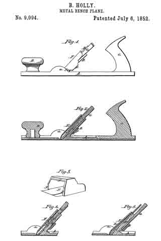
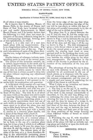
Figure 1, is a side view of a cast iron bench plane with my improvements. Fig.
2, is a longitudinal section of the same. Fig.
3, is a perspective view of the cap. Figs. 4 and 5 are sections of parts of the plane showing the iron, wedge and cap in different positions.

Similar letters of reference indicate corresponding parts in each of the several parts.

The nature of this invention consists, 1st, in certain improvements in the stock and in the cap of the iron which allow the width of the throat to be altered for different kinds of work; 2nd, in certain means by which the cap of the iron is always caused to drop into its place without requiring any adjustment or setting.

To enable those skilled in the art to make and use my invention I will proceed to describe fully its construction and operation.

A, is the stock which consists of a cast iron plate with the stem B, standing up from it at a suitable inclination, and with two projecting pieces, a a, one on each side close in front of the stem. The stem B, is of about the same width as the plane iron and is made of tapering thickness, being rather smaller at the top. The two projecting pieces a a, are of nearly semicircular form and are of such width or thickness, or are at such a distance apart as to allow the plane iron and cap to slide freely between them. The stock is furnished at the back part with a handle C, similar to a common plane handle, and in front of the throat with a knob D.

The plane iron E, is similar in its general character to the iron of a common plane. The cap F, consists of a cast iron plate similar in form to the cap of a common plane iron, but it has a loop f, which is of sufficient width and depth to lit over the plane iron, the stem B, and the wedge G, by which the iron is secured. The bottom parts of the sides of the loop at g, g, form shoulders fitting to the semicircular projecting pieces a, a, of the stock and are at such a distance from the lower edge of the cap that when they rest on the projections the edge of the cap will be just above or within the face of the plane and parallel transversely to it; the edge of the cap is chilled or hardened.

The plane iron E, is placed between the cap F, and the stem B, and the wedge may be inserted between the iron and the stem as shown in Figs. 1 and 2; between the cap and the iron as shown in Fig. 4; or between the back of the stem and the loop f, of the cap as shown in Fig. 5. The first arrangement gives a wide throat which is best for rough work; the second gives a very small throat suitable for planing hard wood or cross grained stud, or for finishing fine work; and the third gives a width of throat about half way between the widths given by the other two arrangements. The difference in the width of the throats is produced by the alteration of the inclination of the iron and cap.

The advantage of having the cap to drop at once with certainty to its place, will be admitted by all accustomed to the use of bench planes, as it dispenses with the necessity of measuring and setting required in the common arrangement; and the want of a simple and sure means of regulating the width of the throat is well known.

What I claim as my invention and desire to secure by Letters Patent, is

1. The loop f on the cap F, in combination with the plane iron E, and the stem B, of the stock in the manner substantially as described, to wit, the said loop fitting over or embracing the plane iron and stem and, allowing the iron to be secured between the cap and the stem by means of a wedge G, placed either between the back of the iron and front of the stem, between the front of the iron and the cap, or between the back side of the stem and back part of the loop, the three positions of the wedge forming three different widths of throat as herein explained.

2. Providing the cap F, with shoulders g, g, which when the cap is placed in the stock of the plane will fall on suitable resting pieces provided in or upon the stock substantially as described.

BIRDSILL HOLLY.

Witnesses:
CHAS. J. MCKEE,
PHILO COWING.

No. 8,796 – Double Plane Iron (Fordyce Beals) (1852)

[paiddownloads id=”10″]8796


UNITED STATES PATENT OFFICE.

_________________

FORDYCE BEALS, OF PITTSFIELD, MASSACHUSETTS.

DOUBLE-PLANE IRON.

_________________

Specification of Letters Patent No. 8,796, dated March 16, 1852.

_________________

To all whom it may concern:

Be it known that I, FORDYCE BEALS, of Pittsfield, in the county of Berkshire, in the State of Massachusetts, have invented new and useful Improvements in Double-Plane Irons; and I do hereby declare that the following is a full, clear, and exact description of the construction and operation thereof, reference being had to the accompanying drawings, and to the letters of reference thereon, it being a part of this specification, in which —

A is the iron, C a section of the cap, and B a dovetail slide or projection of cap.

The nature of my invention consists in an improved arrangement for connecting and adjusting the cap to the iron.

To enable others skilled in the art to make and use my invention I will proceed to describe its construction and operation.

I construct my plane irons of any desired width, thickness, or form, with the following exceptions: In the place of a screw bolt as now used I substitute a dovetail slide formed by an oblong projection with beveled edges, either forged, screwed, or riveted or fastened in some feasible way to inside of cap, as shown at B in accompanying drawings, this projection being placed in the slot made in iron, as shown at B, of corresponding width, and edges of corresponding angle or bevel brings the cap with ease and accuracy to a parallel position with iron and obviates the necessity of a bolthead or projection of any kind on the back side of iron.

Also my improvement consists in an elongation of a portion of the cap to the length or to nearly the length of the iron, the elongation being wholly upon one edge and nearly half the entire width, as shown at C in drawing. To make this arrangement convenient I remove a portion of the iron from the slot upward (the iron being in a working position) the entire thickness and one half or near one half its width, thus giving place for the elongated part of cap as shown at C.

I disclaim all contrivances, arrangements, or forms of cap or iron which together compose a double iron now in general use.

What I claim as my invention and desire to secure by Letters Patent is —

The new and improved mode of fastening and adjusting the cap to the iron by means of a projection and slot forming a dovetail slide giving new facilities for the operation; and also a level surface to the back of the iron; also the elongation of part of the width of the cap and its occupying the place of a removed part of iron, giving the operator new facilities in nicely adjusting cap to edge of iron without removing it from the stack, the same as herein described using for the purpose the aforesaid arrangements of parts or any other substantially the same and which will produce the same effects in like manner.

FORDYCE BEALS.

Witnesses:

JULIUS ROCKWELL,
JAMES D. COLTER.

No. 8,655 – Beveling Plane (Harrison W. Lewis) (1852)

[paiddownloads id=”8″]8655


UNITED STATES PATENT OFFICE.

_________________

HARRISON W. LEWIS, OF BATH, NEW YORK.

BEVELING-PLANE.

_________________

Specification of Letters Patent No. 8,655, dated January 13, 1852.

_________________

To all whom it may concern:

Be it known that I, HARRISON W. LEWIS, of Bath, in the county of Steuben and State of New York, have invented a new and useful Improvement in Beveling-Planes; and I do hereby declare that the following is a full and exact description of the same, reference being had to the annexed drawings, making part of this specification, in which —

Figure 1 is a front elevation; Fig. 2 is a central longitudinal section; Fig. 3 is an end view from the left; Fig. 4 represents the rear side of the guard, and Fig. 5 shows the form of one of the planing cutters.

This invention consists of a plane, or planing instrument, of peculiar form, and furnished with several peculiar devices, so as to be adapted to the purpose of forming at one operation, and with extraordinary accuracy, a double bevel upon the grooved edge of a stile or rail of a panel door.

The stock A of this plane, has a longitudinal groove in the center of the under side thereof; and the spaces between this groove and the sides of the stock, consist of two inclined planes (surfaces) a a, the two planes being at an angle of about eighty degrees with each other, or about fifty degrees (each) with the sides of the stock. The stock is furnished with two cutters B (see Fig. 5) the cutting edges of which conform to the obliquity of the plane surfaces a a, and are fastened by wedges (b) in the manner of common planing tools.

An adjustable vertical guide C passes through the stock between the two cutters, and is secured in the required position by a horizontal screw c; and in the bottom of the guide is a narrow horizontal groove to receive the back of the gage-bar D. This gage-bar extends the full length of the stock A, and the two ends thereof are bent upward, as shown at e e Fig. 2. The forward end of the gage-bar passes up through a vertical groove in left or forward end of the stock (or in a vertical plate attached to the end of the stock), and has a slot (i) through which passes a set screw a whereby the gage-bar is held in the required position. The rear end of the gage-bar enters a vertical groove in the right end of the stock, and is held fast by a set-screw r, which passes through a plate s which is attached to the right end of the stock.

Two horizontal guard-screws E E pass through the stock, near the two ends thereof; and each guard-screw is furnished with a nut F and a collar G, whereby the screws are adjusted in any required position. The front end, or head, of each guard-screw has a shoulder or downward projection t, to the bottom of which is attached one end of a guard-stock H; and to the rear side of the guard-stock, an adjustable guard I is attached by means of two set-screws u u, which pass through two vertical slots v v, (Fig. 4) in the guard, and extending through the guard-stock, the front ends thereof are furnished with thumb-screw nuts x x. The slots v have rebates in the sides thereof (see Fig. 4) to receive the square heads of the screws u, that the heads may not be prominent to the face of the guard.

When the grooved edge of a rail is to be beveled by this plane, the guard is so adjusted as to slide upon the face of the rail, while the bottom of the guide C slides within the groove of the rail; and the gage-bar is so adjusted as to come in contact with the bottom of the said groove when the rail is sufficiently beveled, and thus prevent the cutters from planing off too much.

What I claim as my invention and desire to secure by Letters Patent is —

1. The adjustable gage-bar (D) and the vertical adjustable guide (C), in combination with the double faced plane-stock, all constructed and relatively arranged as herein described.

2. The combination of the guard-screws (E) , guard-stock (F), adjustable guard (I), gage~bar (D), vertical guide (C) and plane-stock (A; the whole being constructed and arranged substantially in the manner and for the purpose herein set forth.

HARRISON W. LEWIS.

Witnesses:

JOHN L. SMITH,
RUFUS PORTER.