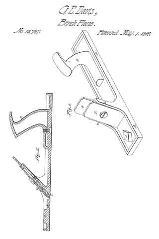
No. 13,745 – Bench Plane Iron (J. Henry A. Bleckmann) (1855)

[paiddownloads id=”26″]13745


UNITED STATES PATENT OFFICE.

_________________

J. H. A. BLECKMANN, OF RONSDORF, NEAR ELBERFELD, PRUSSIA.

BENCH-PLANE IRON.

_________________

Specification of Letters Patent No. 13,745, dated November 6, 1855.

_________________

To all whom it may concern:

Be it known that I, J. HENRY A. BLECKMANN, of Ronsdorf, near Elberfeld, in the Kingdom of Prussia, have invented a new and Improved Plane-Iron; and I do hereby declare that the following is a full and exact description thereof.

The nature of my invention consists in forming a plane-iron by placing between iron plates in the shape of the common double plane-irons a steel plate which may be advanced or drawn back by means of screws or a set screw.

The advantages arising from this my invention are, first, that I can employ well tempered steel plates which have not been injured by the process of welding it to another plate as it is done in the manufacture of common single or double plane iron; second, that I can easily change the cutting iron when necessary for another plate of the same temper and cutting quality; third, that it is cheaper than common plane iron now in use.

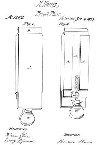
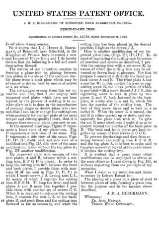
In the annexed drawings, Figure Ia represents a front view of my plane-iron. Fig.
Ib represents a back view of the same. Fig.
Ic represents a side view of the same; Figs.
IIa, IIb, IIc, front, back and side view of a modification; Fig. Id, side view of the same modihcation, taken without the top plate A;
Fig. III another modification.

My improved plane iron consists of two iron plates, A and B, between which a cutting iron, E F G H is placed. In order to keep the cutting iron firm between the front and back plates, I provide them with mortises M M (as seen in Figs. Ia, Ib, Ic) in which I insert screws J J, having nuts L L, by means of which I regulate the cutting iron E F G H. To keep the front and back plates A and B more firm together I provide them with another set of screws C C. When it is required to advance the cutting iron, I unscrew the nuts L L on the back-plate B, and push them and the cutting iron forward as far as necessary, and when the cutting iron has been placed in the desired position, I tighten the screws J J.

Here is another modification of my improved plane iron, (Figs. IIa,IIb, IIc). Instead of regulating the cutting iron by means of mortises and screws as described, I provide the cutting iron with a set screw K, by means of which the cutting iron may be advanced or drawn back at pleasure. For that purpose I construct differently the front and back plates A and B. The front plate A has a mortise M; in this mortise fits a set or regulating screw K, the lower portion of which is provided with a screw thread J J J J ; this regulating screw is kept in place by two pieces L and V, both fastened in the back plate, it works also in a nut R, which fits into the mortise of the cutting iron. The foot of this screw turns and is held in a socket S. When the screw K is turned, the nut R is either carried up or down and consequently the plane iron with it. To give the nut R more steadiness I make it so as to project beyond the mortise of the back-plate B. The back and front plates are kept together by means of four screws C C C C.

To prevent the shavings and dust from entering between the cutting iron E F G H and the top plate A, it is best to make said top plate somewhat curved at the point where it touches the cutting iron.

It is evident that a great many other modifications can be employed to arrive at the same object as I have shown in Fig. III, without departing from the principle of my invention.

What I claim as my invention and desire to secure by Letters Patent is —

The placing of a piece or a plate of steel between plates of iron, forming a plane iron for the purpose and in the manner above described.

J. H. A. BLECKMANN.

Witnesses:
FR. AUG. BUSCHE,
FRIEDR. WILH. ORTMANÜL

No. 13,575 – Plane Bit (Horace Harris) (1855)

[paiddownloads id=”25″]13575


UNITED STATES PATENT OFFICE.

_________________

HORACE HARRIS, OF GORHAM, NEW YORK.

PLANE-BIT.

_________________

Specification of Letters Patent No. 13,575, dated September 18, 1855.

_________________

To all whom it may concern:

Be it known that I, HORACE HARRIS, of Gorham, in the county of Ontario and State of New York, have invented a new and Improved Mode of Adjusting Bench-Plane Irons; and I do hereby declare that the following is a full and exact description thereof, reference being had to the accompanying drawings, making part of this specification, in which —

Figure 1 is a front view and Fig. 2 is a back view of the implement. I give the description “front” and “back view,” etc., from the position of the iron when in a plane stock. The “iron” embraces all the members found in the drawings.

In Fig. 1, A, B, C, are the same parts that are represented by them respectively in Fig. 2, except that in Fig. 1 A, is an iron used in the place of a cap in double irons for planes in common use, and in Fig. 2, A, A, are the side edges of said cap turned over on the back side of said iron to form grooves in which the bit B, (which is the part of the iron which cuts) is designed to be moved up or down for the purpose of cutting a coarse or line shaving. The grooves may be governed by turning the edges of the cap over the whole length, or only parts of the distance.

C, is a thumb screw at the top of the iron which is made to turn, without a screw thread in a back projection A, from the top of the cap, and is held from moving endwise by the head of the screw on the upper side, and by a nut E, pin, or otherwise on the lower side of said projection. The lower end of the screw is made to pass into a nut F, formed in a corresponding projection from the top of the bit. Thus the bit being nicely adjusted in the grooves is kept trim and steady while it is raised or lowered by the screw; and the screw thus arranged in the cap, (which is fast in the stock by a wedge, as are the irons in common planes), and at the same time connecting with the bit, helps to hold that firm to its place while it is in use. The advantages of this plan of adjustment are, that, 1st, it holds the bit more firmly and keeps it truer in its action than any other preceding screw adjustment, and, 2d, it is adapted to the ordinary wedge fastening arrangement in common bench planes, so that it can be readily used without any change of the common plane stock, thus giving it a general adaptation, with but little additional expense, that is, only the expense of the iron.

What I claim as my invention, and desire to secure by Letters Patent of the United States, is —

The adjustment of the cap and bit with the grooves at each side, and of the thumb screw at the top of the cap and bit, for the regulation cf the cut of the bit while the iron is held fast in the stock by the wedge fastening.

I am aware L. K. Wilman has an invention for fixing a plane iron in grooves in the sides of a plane stock, and of regulating the out of it with a screw at the top of the iron and turning in a nut in the stock; but my devices differ essentially from his in these points, viz., 1, that my grooves are in the plane iron itself, and therefore, for use, requires no changes of the stock or wedge, but with the wedge the iron is held firmer than by any arrangement without it; and 2 that my screw is attached to the cap and bit as the plane for working the bit in the grooves made fast in the stock by the wedge.

HORACE HARRIS.

Witnesses:

CHAS. E. UPPERMAN,
J. L. ADAMS.

No. 13,381 – Plane Scraper (Leonard Bailey) (1855)

[paiddownloads id=”24″]13957


UNITED STATES PATENT OFFICE.

_________________

LEONARD BAILEY, OF WINCHESTER, MASSACHUSETTS.

PLANE-SCRAPER.

_________________

Specification of Letters Patent No. 13,381, dated August 7, 1855.

_________________

To all whom it may concern:

Be it known that I, LEONARD BAILEY, of Winchester, in the county of Middlesex and State of Massachusetts, have invented an Improved Plane-Scraper; and I do hereby declare that the same is fully described and represented in the following specification and the accompanying drawings, letters, figures, and references thereof.

Of such drawings, Figure 1, is a side elevation, while Fig. 2, denotes a central vertical and longitudinal section of my improved tool or invention.

In such drawings, A, represents a plane stock or bed which may be constructed of metal and have a handle, B, extended from and above it. The bed is provided with a throat or opening, C, for the scraper or plane cutter D, to pass through, and over this throat and hinged or jointed to the stock (as seen at, x, Fig. 1) so that it may be turned in a direction, either toward or away from the handle, B, is a plate, E, embraced by a screw stirrup or clamp, F, having some equivalent contrivance for fastening the scraper to it.

A forked arm G, is jointed to the upper part of the rear side of the plate, E, and is provided with a female screw, a, for the reception of a male adjusting screw, b, which should be so applied to the top of handle, B, as to be immovable with respect thereto except being rotated in a transverse direction.

For this purpose the rod is provided with a journal, d, extending through a projection, I, having rollers, e, f, arranged on opposite sides of the said projection as seen in the drawings.

The movable plate and its screw clamp may be termed the holder of the scraper or plane iron. By means of the adjusting screw the inclination of the scraper to the lower surface of the bed or stock may be adjusted as occasion may require it often being desirable to accomplish this result in order to prepare the tool for a correct performance of its duty — the same depending on the particular kind or character of the wood on which we may wish to employ it — the specific object of such tool being to scrape or pare down the surface of such wood.

As the turning points of the cutter holder, are arranged a short distance above the bottom surface of the stock (as seen at, x, in Fig. 1) it will be observed that any movement of the holder on such points, will either elevate or depress the lower edge of the cutter scraper. Thus by means of the adjusting screws or mechanism, the fineness of the cut of the scraper may be modified.

The utility and advantage of a scraper or smoothing plane constructed in the above described improved form must be evident to a skilful workman on inspection of it.

I claim —

Combining the scraper or plane cutter with the stock by means of the movable holder and its adjusting mechanism substantially as specified.

In testimony whereof, I have hereunto set my signature this eleventh day of July A. D. 1855.

LEONARD BAILEY.

Witnesses:
R. H. EDDY,
F. P. HALE, Jr.

No. 12,787 – Bench Plane Stock (George E. Davis) (1855)

[paiddownloads id=”23″]12787


UNITED STATES PATENT OFFICE.

_________________

GEO. E. DAVIS, OF LOWELL MASSACHUSETTS.

BENCH-PLANE STOCK.

_________________

Specification of Letters Patent No. 12,787, dated May 1, 1855.

_________________

To all whom it may concern:

Be it known that I, GEORGE E. DAVIS, of Lowell, county of Middlesex and State of Massachusetts, have invented a new and useful iron plane-stock and a new method of attaching the cutting-irons to the stocks to be used by carpenters and woodworkmen generally to be used and adopted instead of the old wood plane, molding and other tools which have been heretofore used; and I hereby declare that the following is a full, clear, and exact description of the manner of making and using the same, when taken in connection with the accompanying drawings and letters of reference marked thereon, in which —

Figure 1, denotes a perspective view. Fig. 2, a longitudinal and vertical section through the center of the same.

The nature of my invention consists in constructing the main body of planes, molding tools, &c., of metal, which being very thin, presents little or no impediment to the shavings passing out as they are cut from the wood, using an iron or wood handle attached to these planes. By means of the lower portion of the plane stock thus made, the hand of the operator is very near the face of the plane when it is used and consequently equally near the face of the stock which is being dressed. And my invention further consists in securing the cutting irons to the iron or other plane or tool stock, by means of a single screw (instead of the old chip) which screw secures both the cap and the cutting iron together, and both of them to the iron tool or plane stock, and by forming a lip in the back part of the throat so as to fill it and thus give a smooth even surface to the face of the plane, all as hereafter described.

To enable others skilled in the art to make and use my invention, I will proceed to describe its construction and operation.

I construct a malleable iron plane stock as seen at A, A, of the drawings, to this stock I attach a handle which may be made of iron or wood as seen at B, and this is attached to the plane stock by the screw H. On the upper side of the plane stock I form a projection as seen at C at each side of which is formed, a projection as seen at G, so as to receive the cutting iron, which differs from all other plane irons in being constructed and attached to the plane as follows, both the cutting iron D and the cap E being secured to each other and to the plane stock G one screw as seen at F which is effected by forming an oblong slot in the cutting iron about one inch long, and wide enough to receive the screw, and through which the screw passes, this slot being for the purpose of receiving this screw, and also of allowing the cutting iron to be moved down as it wears in using, in the throat of the plane immediately back of the cutting iron, I form a lip as seen at I, so as to fill the recess caused by the bevel on the edge of the plane iron in the ordinary plane, thereby preventing its catching, and filling with portions of wood, as it is used, and presenting a smooth surface to the wood.

At J can be seen the “start” which is for the purpose of starting the iron back or upwards when desired.

To use my invention of improved plane I first set the proper edge upon the cutting iron, then place this iron into its position in the plane stock then properly place the cap in its position upon the cutting iron, and then place the screw F in its position and turn it to a bearing, by a screw driver or otherwise and the plane is ready for use.

This same description will answer for the single cutting iron, excepting the description of the cap, the use of molding tools being similar to the previous description for planes.

Having thus described my invention what I claim as my invention and wish to secure by Letters Patent, is —

The metal plane stocks having a formation of a lip I in the back part of its throat so as to fill the recess which would otherwise be below the level of the cutting irons so as to present a continuous smooth surface to the plane excepting the edge of the cutting irons and throat forward of them, for the outward passage of the shavings essentially in the manner and for the purposes set forth.

GEO. E. DAVIS.

Witnesses:
R. N. HAYDEN,
JAMES WILSON.

No. 12,234 – Bench Plane (William C. Hopper) (1855)

[paiddownloads id=”15″]12234


UNITED STATES PATENT OFFICE.

_________________

WILLIAM C. HOPPER, OF PITTSBURG, PENNSYLVANIA.

BENCH-PLANE.

_________________

Specification of Letters Patent No. 12,234, dated January 16, 1855.

_________________

To all whom it may concern:

Be it known that I, WILLIAM C. HOPPER, of Pittsburg, in the county of Allegheny and State of Pennsylvania, have invented a new and useful Improvement in Planes; and I do hereby declare that the following is a full and exact description thereof, reference being had to the annexed drawings, forming part of this specification, in which —

Figure 1, is a longitudinal sectional through the center of the plane; Fig. 2 is a perspective view of the mouth piece of my improved plane. Fig. 3, is a perspective view of a section of my plane through x. x, in Fig. 1, turned up so as to show the underside of the plane, and with the mouth piece removed. Fig. 4, is a representation of the underside or face of the plane to show the position of the mouth piece.

My invention is especially designed for planes to be used in fine work, where great smoothness of finish is required, but is also very applicable with great advantage to all kinds of planes, from the smoothing plane to the jack plane.

It consists in so arranging the parts of the plane that the chisel is placed in front of its wedge, and rests against the front shoulder in the cavity of the plane, in combination with the use of a mouth piece on the face of the plane in front of the edge of the chisel to serve as a rest for the chisel and to confine the throat of the plane.

In order to enable others skilled in the art to make and use my improved plane I will proceed to explain its construction and operation.

In the drawings a, is the mouth piece which may be constructed of iron, bone, brass, hardwood or other suitable material.

The shape of the mouth piece shown in Fig. 1, is that which I prefer, but any other shape may be adopted which will accomplish the same object, as I do not desire to confine my invention to the peculiar shape of mouth piece herein described. The mouth piece is attached to the plane by a screw s, which passes through the plate b, of the mouth piece. When set in the plane, the surface of the plate b, lies flush with the face of the plane, and rests on three wood screws s’, s’, s’, which are nicely adjusted so as to afford a firm bed for it, parallel to the face of the plane. The mouth piece is of the same width as the chisel or bit c. The two arms d, d, at either side of the mouth piece, project upward into the cavity of the plane, at the same angle to the face of the plane as that at which the chisel is to be set. These arms serve as rests for the end of the bit c.

The bit or chisel is inserted in the plane in front of the wedge e, and rests against the front shoulder, against which it is pressed by the wedge. The bit is thus held firmly in its place throughout its whole length, which prevents it having any spring, and causes it to work much more smoothly. A slight space is left between the points or edge of the bit c, and the edge of the face of the mouth piece, sufficient to allow of the passage of the chip or shaving between them into the cavity of the plane; but the mouth piece is so close to the edge of the bit as to prevent the plane ripping or splintering the wood, even in the slightest degree, which would be the case if the plane had an open throat; and this arrangement causes the plane to work so smoothly that it may be used even for planing veneers, which cannot be done at all with safety with any plane of the ordinary construction. My arrangement in combination with the use of a mouth piece also enables me to dispose with the use of a cap or double bit.

By constant use the face of a plane gradually wears away, in which case it will be necessary to sink the mouth piece lower down in the hole made for its reception. If the mouth piece were sunk down at right angles to the face of the plane, it is evident, that as the bit is set in the plane at an angle of about 45 degrees, the bit as the plane wears away would recede from the mouth piece; it would no longer rest against the arms of the mouth piece, and the throat of the plane, through which the shavings pass would become too wide. To remedy this inconvenience and enable the mouth piece to be accurately adjusted to the bit, I adopt the following arrangement: The extreme edge of the mouth piece is beveled to the same angle as that at which the bit of the plane is set, as will be seen in Fig. 1; the corresponding wall of the recess in which the mouth piece is sunk, (marked f, in Fig. 3,) is also inclined at the same angle.

When the plane requires to be refaced, the screw, s, is unscrewed, and the mouth piece is taken out. The adjusting screws, s’, s’, s’, are lowered as much as it is desired to sink the mouth piece, and the mouth piece is replaced. Now as the edge of the mouth piece which rests against the wall of its recess, as well as the wall f, itself is beveled, the mouth piece in sinking into its recess, is pushed forward toward the bit, just as far as the bit has receded, and their relative position is exactly maintained, so that the sides of the bit will rest as before against the projecting arms of the mouth piece. The screw s, is also set into the plane at an angle, so that it allows for this lateral adjustment of the mouth piece, and avoids the necessity of making a new hole for the screw s.

As I remarked before, the form of the mouth piece may be varied without altering the principle involved; the simplest form which can be used, is to screw a plate of metal, countersunk into the face of the plane, immediately in front of the edge of the bit; but this only partially accomplishes the object of my invention as it does not serve as a rest for the end of the bit, nor is it capable of so easy and accurate adjustment.

Having thus described my improvement in planes, what I claim as my invention and desire to secure by Letters Patent, is —

The constructing of planes with the chisel or bit set in front of its wedge, in combination with the use of a mouth piece, substantially in the manner and for the purposes hereinbefore described.

WM. C. HOPPER.

Witnesses:
N. B. KENASTON,
WM. N. HOWARD.

No. 13,957 – Patternmakers Core Box Plane (John P. Robinson) (1855)

[paiddownloads id=”27″]13957


UNITED STATES PATENT OFFICE.

_________________

JOHN P. ROBINSON, OF MATTEAWAN, NEW YORK.

PLANE FOR FINISHING GROOVES IN PATTERNS &c.

_________________

Specification of Letters Patent No. 13,957, dated December 18, 1855.

_________________

To all whom it may concern:

Be it known that I, JOHN P. ROBINSON, of Matteawan, in the county of Dutchess and State of New York, have invented a new and Improved Plane for Cutting or Forming Grooves Designed Chiefly for Patternmakers’ Use; and I do hereby declare that the following is a full, clear, and exact description of the same, reference being had to the annexed drawings, making a part of this specification, in which —

Figure 1, is an ened view of my improvement. Fig. 2, is a longitudinal verticle section of ditto, the plane of section being through the center. Figs. 3, 4, 5 are end views of my improvement in different positions showing the manner in which the grooves are formed. Fig. 6, is an end view of ditto, the form of the plane being slightly varied from those shown in the proceeding figures. Fig. 7, is a perspective view of the block of wood showing a taper groove formed by my improvement.

Similar letters of reference indicate coresponding parts in the several figures.

My invention consists in having the stock of the plane made in triangular or three sided prismatic form the cutting edge of the iron being at the junction of it’s two lower sides and shaped to correspond to the form of the sides as will be presently shown and described whereby half round and other shaped grooves of different sizes may be cut.

To enable those skilled in the art to fully understand and construct my invention, I will proceed to describe it.

A, represents the stock or body of the plane which is of triangular or three sided prismatic form.

B, represents the plane iron which passes through the center of the upper side of the plane stock, the cutting edge of the plane iron is pointed or has beveled edges corresponding with the inclination of the two lower sides of the stock as shown clearly in Fig. 1.

In Figs 1, 3, 4 and 5, the two lower sides of the stock meet at a right angle, and in Fig. 6 the angle formed by the junction of the two lower sides is acute or less than a right angle.

The width of the plane iron, B, is such that each of the lower sides of the stock will have a suitable length of cutting edge of the iron projecting through it, a suitable thwart C, being made through the stock as shown in Fig. 2.

The plane is used in the following manner: The stuff in which the groove is to be cut is marked or lined to indicate the desired width of the groove. The spaces between the marks or lines may then be chipped or roughed out a requisite depth as desired with a gouge or other instrument, or the whole of the groove may be cut with the plane, if the latter plan is preferred a shallow cut is made by the plane on each line or mark, and the edge of the plane formed by the junction of the two lower sides is placed in one of these cuts as shown in Fig. 3 and the plane operated similar to other tools of the kind. One side or edge only of the plane iron cuts in the groove and when the plane has cut one half of the groove it, the plane, will be in an upright position as shown in Fig. 4. The lower edge of the stock is then placed in the opposite cut and the other half of the groove is cut. The plane stock being of triangular form rests against the edges of the groove and determines its depth, so that if the two lower sides of the stock are at right angles to each other, the groove will be of semi-circular form, as shown in Figs. 1, 3, 4 and 5 but if the lower sides form an acute angle as shown in Fig. 6 the groove will be a semi-ellipse deeper than it is wide and if the sides form an obtuse angle the groove will be wider than it is deep.

Grooves may be made of taper form as shown at D, fig 7, and they may be made of any width and depth, the depth of course corresponding to the width and angle formed by the two lower sides of the stock.

The above implement or tool is intended chiefly for patternmakers’ use, where grooves of varying sizes require to be made.

Having thus described my invention, what I claim as new and desire to secure by Letters Patent is,

Constructing the plane stock A, of triangular or three sided prismatic form, the two lower sides forming a greater or less angle with each other and the plane iron, B, fitted in the stock as shown for the purpose set forth.

JOHN. P. ROBINSON.

Witnesses:
CHAUNCEY GREEN,
ADOLPHUS VANDEWATER.