No. 16,309 – Adjusting Bits Of Carpenter’s Planes (Thomas D. Worrall) (1856)
UNITED STATES PATENT OFFICE.
_________________
THOMAS D. WORRALL, OF LOWELL, MASSACHUSETTS.
ADJUSTING THE BITS OF CARPENTERS’ PLANES.
_________________
Specification of Letters Patent No. 16,309, dated December 23, 1856.
_________________
To all whom it may concern:
Be it known that I, THOMAS D. WORRALL, of Lowell, in the county of Middlesex and State of Massachusetts, have invented certain new and useful Improvements in Carpenters’ Bench-Planes; and I do hereby declare that the same is fully described and represented in the following specification and the accompanying drawings, of which —
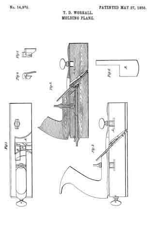
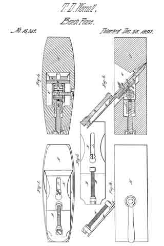
Figure 1, is a top view. Fig. 9, a side elevation. Fig. 3, a vertical and longitudinal section, and Fig. 4, a horizontal and longitudinal section of one of my improved bench planes, the latter section being taken through the pinion gear by which the plane-iron or cutter may be elevated or depressed within the throat of the stock.
In the said drawings, A, denotes the stock, B, the cutter or plane-iron, and, C, the throat of the stock.
In order to hold the plane-iron within the stock, I employ a clamp or piece of metal, D, made so as to embrace a dovetailed rack bar E, fixed to the rear side of the cutter, B, as shown in Figs. 3 and 4. The clamp is arranged within a cavity or recess, F, formed in the stock and leading out of the rear side of the throat thereof. A female screw, a, is made through the rear part of the clamp and so as to receive a male screw cut on the end of a long rod, G, which extends backward through the stock and has a hexagonal head, c, as shown in the drawings. The rack, E, is provided with teeth on its rear side to cooperate with a pinion, H, arranged and made to turn within the clamp, and to have its shaft, I, extended laterally through the plane stock and formed so as to receive a key, by which it and the pinion may be put in rotation for the purpose of regulating the distance of the cutting edge of the plane-iron relatively to the lower surface of the stock. Such distance having been obtained, the clamp, D, is to be brought into action or to be drawn backward so as to act upon the dovetail of the rack and so as to draw the plane-iron firmly against the rear face or side of the throat and hold said plane-iron in its proper place.
From the above it will be seen that we not only have a means of clamping the plane-iron, but of readily adjusting it in the stock. Furthermore a cap iron, K, is applied to the plane iron for the purpose of enabling it to plane cross grained stud, a top view of said cap and the plane-iron being represented in Fig. 5. Instead of making this cap straight from end to end, or with its under surface a plane surface, as it is usually made, I give to it a curved form throughout its entire length as shown in Fig. 3, and provide the cap with a slot, L, arranged in it as shown in the drawings. A clamp screw, M, extends through the slot and into the plane-iron, the same being for the purpose of confining the cap to the plane-iron. In order to regulate the longitudinal movement of the cap iron, or plane-iron I apply to the cap and plane-iron an adjusting screw, as shown at N. Thus it will be seen that the plane stock is not employed as a bearing for the device by which the cap is held to the plane-iron, such device being entirely independent of the stock.
By making the cap curved in manner as described its lower end may be forced down into perfect contact with the upper surface of the plane-iron, and will not spring there from so as to admit shavings or pieces of wood between it and the cutting edge of the plane while it is in use. It is well known that when the cap is made perfectly flat it is liable to be raised off the iron by slivers or chips which may become wedged between their lower ends, the same serving to interrupt the proper action of the cap. By making the cap in my improved manner and by applying a clamp to it so as to be independent cf the stock in the way above described, I am not only able to effect the proper fixation of the cap iron, but can adjust the plane iron or move it up and down without disturbing the said adjustment of the cap thereon.
I claim —
The arrangement of the rack and pinion and the clamp so that while the pinion is placed within the clamp, the rear or dove-tailed sides of the rack bar shall serve as bearings for the clamp to work against.
In testimony whereof I have hereunto set my signature this eighteenth day of September, 1856.
THOMAS. D. WORRALL.
Witnesses:
R. H. EDDY,
F. P. HALE, Jr.