No. 20,882 – Shoemaker’s Edge Plane (Freeman Killbrith) (1858)

[paiddownloads id=”78″]20882


UNITED STATES PATENT OFFICE.

_________________

F. KILLBRITH, OF PEMBROKE, MASSACHUSETTS.

SHOEMAKER’S EDGE-PLANE.

_________________

Specification of Letters Patent No. 20,882, dated July 13, 1858.

_________________

To all whom it may concern:

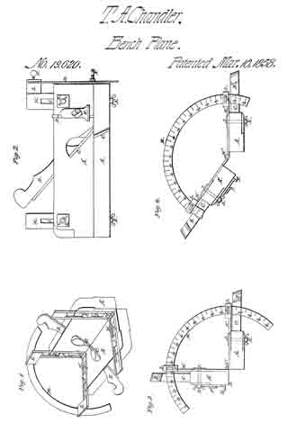
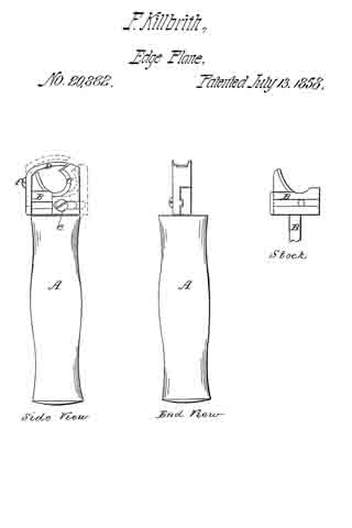
Be it known that I, FREEMAN KILLBRITH, of Pembroke, in the county of Plymouth and State of Massachusetts, have invented a new and useful Improvement on an Implement or Tool called the “Edge-Plane,” Used for the Pairing or Trimming the Edges of Boots and Shoes; and I do hereby declare the following is a full and exact description of said tool, reference being had to the accompanying drawings and to the letters of reference marked thereon.

The nature of my invention consists in attaching to the shank of the edge plane a movable guard which by means of a screw and slide can be moved toward the edge of the knife as the knife wears away by use, so that the space between the edge of the knife and the guard can be regulated at pleasure; and also in making the knife itself movable so that it can be set at any desired gage, and also be removed from the shank entirely to be ground or sharpened.

To enable others to make and use my invention I proceed to describe its construction and operation, reference being had to the accompanying drawings.

A is a common wooden tool handle in which is inserted solid in the end, the iron shank B to which is attached the guard C and the knife D.

C is a movable guard fastened to the shank B by the screw e and which can be moved from right to left as desired and held in its place by the screw e or wholly removed from the shank B.

D is the knife fastened to the shank B by I the screw f which works in a slot in the knife, so that it can be raised or lowered and set to any required gage or by unscrewing entirely be removed from the shank to be ground or sharpened.

To operate this tool with this improvement, when the edge of the knife is worn away by use, by loosening the screw e, the guard C can be moved to the left to the edge of the knife D and by tightening the screw e set at any required distance from the edge of the knife D.

To set the knife to any gage for paring a sole the screw f is loosened and the knife raised or lowered to the desired gage and the screw fastened.

To remove the knife from the shank, remove the screw f wholly.

What I claim as my invention and desire to secure by Letters Patent is —

The attachment to the edge plane now in use and known as Dunham’s patent, of the movable guard C with its screw e, the guard being movable to and from the edge of the knife D, and sliding on the face of the shank, B; and also the attachment to the shank B of the knife D with its screw f working in a slot, and raised or lowered to any desired gage for paring soles, and which knife D can be wholly removed from the shank B by unscrewing the screw f, and so ground or sharpened, and be replaced by a new knife if necessary.

FREEMAN KILLBRITH. [L. S.]

Attest:
JOSEPH COBB,
B. STREETER.

No. 19,130 – Crozing Plane (S.G. Crane) (1858)

[paiddownloads id=”69″]19130


UNITED STATES PATENT OFFICE.

_________________

S. G. CRANE, OF ROCHESTER, NEW YORK.

CROZING-PLANE.

_________________

Specification of Letters Patent No. 19,130, dated January 19, 1858.

_________________

To all whom it may concern:

Be it known that I, S. G. CRANE, of Rochester, in the county of Monroe and State of New York, have invented a new and useful Improvement in Crozing-Planes for Coopers; and I do hereby declare that the following is a full and exact description thereof, reference being had to the accompanying drawings and to the letters of reference marked thereon.

Figure 1, is a plan of the instrument.
Fig. 2, is a transverse section.

The nature of my invention consists in constructing crozing planes with two adjustable circular plates P so arranged as that their radius may be changed to suit barrels, half barrels, &c., and in attaching the knife V to one of said plates P.

The “board” M, I construct in the usual way also the block K. The plates P, are attached to said block by screws J. There are slots in the plates for the screws J to pass through, and they permit the changes shown by the dotted lines in Fig. 1. The slots are covered by the Washers C.

The knife V is attached to the rear plate P by the screw Y and its nut D. Said nut is a flat plate of about the same size as the shank of the knife, and answers as a gage for the depth of cutting when the plates are set out for smaller circles, as seen in Fig. 1 by the dotted lines, and at such times the knife V requires no readjusting, it being adjusted to the rear plate, is moved with it.
The spur B on the rear plate answers as a gage for the other plate.

What I claim, is —

The construction and arrangement of the adjustable plates P, and the arrangement of the knife V, as, and for the purposes specified.

S. G. CRANE.

Witnesses:
FERDINAND SEIFRIED,
LOUIS ERNST.

No. 19,229 – Tool For Manufacturing Splint Baskets (Artemas Baker) (1858)

[paiddownloads id=”70″]19229


UNITED STATES PATENT OFFICE.

_________________

ARTEMAS BAKER, OF TEMPLETON, MASSACHUSETTS.

TOOL FOR MANUFACTURING SPLINT BASKETS.

_________________

Specification of Letters Patent No. 19,229, dated February 2, 1858.

_________________

To all whom it may concern:

Be it known that I, ARTEMAS BAKER, of Templeton, in the county of Worcester and State of Massachusetts, have invented a new and useful Tool for Riving Out Basket Stuff, of which the following is a full, clear, and exact description, reference being had to the accompanying drawings, making part of this specification, in which —

Figure 1 is a. plan of the bottom of the tool. Fig. 2 a longitudinal vertical section of the same on the line x, x, of Fig. 1. Fig. 3 a transverse vertical section on the line y, y, of Fig. 1.

In manufacturing thin strips of wood to be used for basket stuff, chair bottoms and for other purposes, it has been customary to rive out the slip and afterward dress or finish its surface, this causes considerable delay and expense in the preparation of the stuff. It is obvious that if a plane is used having an opening in the top of the stock for the slip or shaving to pass out at, as in the ordinary bench plane, that the slip must be bent up so abruptly as it is separated from the piece of stuff that the fibers of the wood will be broken or crippled and the value of the article produced be materially diminished.

The object of my present invention is to produce a tool with which these slips may be cut from at piece of stuff with their surfaces smoothed at one operation.

That others skilled in the art may understand and use my invention I will proceed to describe the manner in which I have carried out the same.

In the drawings A, is the stock, longitudinally through which for a considerable portion of its length is formed a groove or recess B, which is open at the rear end of the stock at a, for the passage of the slip of wood after it has been separated from the large piece of stuff. To the bottom or face of the stock is secured a guard plate C, having an inclined edge at b, alongside of this plate is the cutting iron D made of thicker plate than the guard C, its cutting edge at c, is beveled on the inner side (as in Fig. 3) and inclines to correspond with the edge b, — the screws d, by which this iron is held to the stock pass through slots e, in the iron so that as the edge is worn or ground down the iron may be advanced and the edge c, be kept in the proper position, this edge is kept at such a distance below the edge b, as will give the proper thickness to the slip — overlapping parts of the guard C, and the iron D is a guide E, which is secured to the stock by screws f, the straight edge g of this guide, runs in contact with the side of the plank from which the slips are being cut, and the edge c, being inclined at an acute angle to the guide or to the path of the plane separates the slip from the piece of stuff’ by cutting the fiber and not by riving or rending it oft, and the surface from which the slip is taken off is left smooth so that when the next slip is taken off, both of its sides will be smooth enough for use without any subsequent. finishing. The slip as it is separated from the plank passes through the groove B, out from the plane at a, without having been bent up in such. a manner as to injure the integrity of its fibers.

I am aware that planes have been used having the edge of the iron inclined to the path of the plane. Therefore I do not claim this feature alone; but

What lf claim as my invention and desire to secure by Letters Patent is —

The above described tool consisting essentially of the guide E — the plate C, and the horizontal iron D, with its inclined edge c, in connection with a horizontal recess B, and opening at operating in the manner and for the purpose substantially as set forth.

ARTEMAS BAKER.

Signed in presence of —
ERASTUS O. EDERY,
DEXTER GILBERT.

No. 19,359 – Securing The Plane Iron To Its Stock (P.A. Gladwin) (1858)

[paiddownloads id=”71″]19359


UNITED STATES PATENT OFFICE.

_________________

P. A. GLADWIN, OF BOSTON, MASSACHUSETTS.

METHOD OF SECURING THE PLANE-IRON TO ITS STOCK.

_________________

Specification of Letters Patent No. 19,359, dated February 16, 1858.

_________________

To all whom it may concern:

Be it known that I, P. A. GLADWIN, of Boston, in the county of Suffolk and State of Massachusetts, have invented a new and useful Improvement in Joiners’ Planes; and I do hereby declare that the following is a full, clear, and exact description of the same, reference being had to the annexed drawings, making a part of this specification, in which —

Figure 1, is a longitudinal vertical and central section of my iinproveinent. Fig. 2, is a transverse section of do, taken in the line (x), (x), Fig. 1, and looking in the direction indicated by the arrow. Fig. 3, is a plan or top view of do.

Similar letters of reference indicate corresponding parts in the several figures.

This invention consists in a novel manner of securing the iron in the plane, as hereinafter described, whereby the iron may be readily adjusted in the plane and at the same time firmly secured therein.

To enable those skilled in the art to fully understand and construct my invention I will proceed to describe it.

A, represents the stock of a plane constructed externally in the usual way and provided with an ordinary cutter or “iron” B.

C, is the “throat” of the plane in which the iron B, is placed or fitted and secured. This throat is not provided with the usual grooves at its sides (a) to receive a wooden wedge as ordinary planes, the sides of the throat being perfectly vertical and the space between the sides being equal to the width of the iron B, as shown clearly in Fig. 2. The back (b) of the throat C, has the usual inclination, and its front is of double inclined form as usual and shown at (c) (d) Fig. 1. On the inclined part (c) of the front of the throat C, a plate D, is placed. This plate has an oval opening (e) made in it as shown clearly in Fig. 2, and the lower edge of the plate has a foot piece or projection (f) at each end, the lower surfaces of which are parallel with the outer surface of the cover or cap E, of the iron, see Fig. 1.

F, is a plate on the inner side of which a projecting ledge or bit (g) is formed. This plate is secured to the part (c) of the front side of the throat by a screw (d’) which passes through the oval opening (e) in the plate D, the plate being allowed to turn on said screw and the ledge or bit (g) also fits within this opening as shown clearly in Figs. 1 and 2. The ledge or bit (g) is not at the center of the plate F, but is rather at one side of it, the screw (d’) passing through one end of the ledge or bit (g) as shown clearly in Fig. 2. The plate F, is provided with a thumb piece (h) at its upper end.

In consequence of having the bit (g) placed at one side of the center or screw (d’) and having said bit fitted within the oval opening (e) of the plate D, the plate D, will be raised and lowered turning the plate F, on its screw or center (d and it will be seen that when the plate F, is turned in the direction indicated by arrow (1) the foot pieces or projections (f), (f), will be forced down or against the cap or cover E, of the iron B, and will retain the iron firmly in its place as shown in black in Fig. 1, and in red in Fig. 2. By turning the plate in the opposite direction as indicated by arrow (2) the foot pieces or projections (f), (f) will be raised and the iron may be entirely withdrawn from the stock or adjusted or set as desired and then firmly secured by turning plate F, in the direction indicated by arrow 1.

This invention is extremely simple and allows of the ready adjustment of the iron.
It may be applied to any ordinary plane with the greatest facility, the device being made of varying sizes to suit different sized planes.

Having thus described my invention what I claim as new and desire to secure by Letters Patent, is,

The two plates D, F, constructed as shown, viz., the plate D, being provided with the foot pieces or projections (f), (f), and the oval opening (e), and the plate F, provided with the bit (g) and pivoted to the part (c) of the throat C, so that the bit may work within the oval opening (e) of the plate D, substantially as and for the purpose set forth.

P. A. GLADWIN.

Witnesses:
SAMUEL CALDIROTT,
J. B. CALDIROTT.

No. 19,539 – Floor Plane (Charles E. Barlow) (1858)

[paiddownloads id=”72″]19539


UNITED STATES PATENT OFFICE.

_________________

CHARLES E. BARLOW, OF PHILADELPHIA, PENNSYLVANIA.

FLOOR-PLANE.

_________________

Specification of Letters Patent No. 19,539, dated March 9, 1858.

_________________

To all whom it may concern:

Be it known that I, CHARLES E. BARLOW, of the city and county of Philadelphia and State of Pennsylvania, have invented a new and useful Improvement in Planes for Planing Decks of Vessels and Boarded Floors; and I do hereby declare that the following is a full and exact description thereof, reference being had to the accompanying drawing, and to the letters of reference marked thereon, making a part of this speciflcation.

The nature of my invention consists in providing an ordinary carpenter’s plane with a frame, so formed and connected as to enable the operator to stand in the most advantageous position while planing the decks of vessels, boarded floors and other similar surfaces.

Figure 1 is a longitudinal elevation, Fig. 2 is an end view and F ig. 3 is a plan of my improved plane.

A represents a carpenter’s plane of the usual shape having a pivot (B) firmly fixed to each side, said pivots (B) working freely in the bearings formed on the lower part of an iron frame (C). The upper part of the iron frame (C) passes through the lower stay of the wood frame (D) and is secured thereto by a key (E). The upper part of wood frame (D) is formed somewhat like the handles of a plow, the length of which may be made to suit the workman. The total length of the whole (for a man of a medium height) is about five feet. The plane (A) may be detached from the iron frame (C) by withdrawing the pins (E).

When planing off certain kinds of timber I find it advantageous to weight the plane, by attaching a plate of lead to the top of the (A) to slide more steadily over the article being planed but relieves the operator from the necessity of pressing the said plane (A) on to the said article being planed.

The workman when using my improved plane can place himself in any desirable position without moving the plane (A) from the article being planed. That is to say in consequence of the frame (C) being attached to the plane (A) by the pivots B as above stated-the operator may elevate or depress the handles of frames (D) and (C) without affecting the position of the plane A which will therefore in all cases accommodate itself to the work.

The plane A and its connections are worked backward and forward substantially in the same manner as an ordinary plane when being used on a carpenter’s bench; and the decks of vessels, boarded fioors and other similar surfaces can be thereby planed more expeditiously, and with far less manual labor than is required by the usual mode of operation, which is not only tedious and laborious, but painful in consequence of the workman being compelled to rest on his knees while performing the same.

I do not claim broadly the manner of connecting the handle with the stock. But

What I do claim, as a new article of manufacture, is —

The construction of a self adjusting floor plane, with its handle or handles hinged to the stock substantially as described, for the purposes set forth.

CHARLES E. BARLOW.

Witnesses:
JAMES ECCLES,
JOHNN CLOUDS.

No. 19,620 – Joiner’s Beveling Plane (T.A. Chandler) (1858)

[paiddownloads id=”73″]19620


UNITED STATES PATENT OFFICE.

_________________

T. A. CHANDLER, OF ROCKFORD, ILLINOIS.

JOINER’S BEVELING-PLANE.

_________________

Specification of Letters Patent No. 19,620, dated March 16, 1858.

_________________

To all whom it may concern:

Be it known that I, T. A. CHANDLER, of Rockford, in the county of Winnebago and State of Illinois, have invented a new and Improved Bevel-Fillister and Rabbet-Plane Combined; and I do hereby declare that the following is a full and exact description thereof, reference being had to the accompanying drawings, in which —

Figure 1 is a perspective view; Fig. 2, a side view, and Figs. 3 and A end views. Like letters designate like parts in the several views.

The two planes A, and A’, separately considered, correspond to a rabbet plane, provided with keys B, and plane irons C, in the ordinary manner. Molding planes in some instances may be substituted. The cutter D, gage E, and set screw F, are attached to the side of the plane, in the usual way, and for the ordinary use. The two planes are connected together by the jointed slides H, and H’, Figs. 1 and 2. These slides fit into corresponding grooves or gains in the side of the planes so that the slides will be flush with the side of the planes. In the slides are elongated slots I, which receive the shank of the bolts J, which shank passes through the plane, and has a thumb screw K, on the opposite side as seen in Figs. 2 and 3. In each slide is an elongated recess or depression, which receives the bolt head as represented at L, Figs. 1 and 2. The slides being thus formed and provided with a hinge joint at H”, allows the planes to be moved to any position or angle upon the slides, and secured in place, by the bolts and thumb screws J, and K.

From the slide H”, extend two arms, L, L, in the outer ends of which are slots to receive the sector M, as shown in Figs. 1, 3, and 4. The set screws N, N, enter the slots, for the purpose of holding the sector in place, and thereby the planes, in the desired position or angle. By means of the degrees indicated on the sector, the planes may be set so as to cut at any desired angle.

The planes may be moved so as to cut at various angles, and may be reset so as to cut at any previous form of angle, by noting the degree on the sector. The planes may be set at right angles so as to have the character of a fillister plane, for cutting grooves. By extending one plane from the other, at right angles, they form a raising plane, for cutting or raising panels. By turning them at an acute angle, they become a bevel plane. By placing the planes at right angles so that the face of one plane will be level with the side of the other, similar to the position of Fig. 3, they become a halving plane. By extending one plane from the other so that one is set at an obtuse angle to the other, similar to the position of Fig. 4, they will bevel moldings for pilasters and other similar purposes. The plane may be made to cut moldings at other angles than those described, and may be set in various other positions than those described, which positions will readily be suggested in the practical operation of the plane, and will not change the nature of my invention.

By making slots in the arms of the hinges H, H, and fastening them to the plane stocks by thumb screws, so that they can be adjusted, and fastened in the position desired, the plane can be adjusted to plane flat bevels, or bevels of a small angle on boards of various thickness on both sides of the board at the same time, which cannot be done with any plane made prior to my invention.

Having described my invention so as to enable any person skilled in the art to make and use it, I claim —

Making one or both plane stocks adjustable, on the arms or shanks of the hinges, so as to plane bevels of the same angle, on boards of various thicknesses substantially as described.

THOS. A. CHANDLER.

Witnesses:
W. H. BURRIDGE,
JAMES A. BRIGGS.

No. 20,459 – Spokeshave (Charles H. Weston) (1858)

[paiddownloads id=”74″]20459


UNITED STATES PATENT OFFICE.

_________________

C. H. WESTON, OF NASHUA, NEW HAMPSHIRE.

SPOKESHAVE.

_________________

Specification of Letters Patent No. 20,459, dated June 1, 1858.

_________________

To all whom it may concern:

Be it known that I, C. H. WESTON, of Nashua, in the county of Hillsboro and State of New Harnpshire, have invented a new and useful Spokeshave; and I do hereby declare that the following is a full, clear, and exact description of the constriiction and operation of the same, reference being had to the accompanying drawings, forming a part of this specification, in which —

Figure 1, is a perspective view of the shave in readiness for operation, Fig. 2, is a view of the cap or holder; and Fig. 3, is a section of the handle with the cap and cutter removed.

Similar parts are indicated by the same letters in all the figures.

The nature of my invention consists, first, in confining the cutter by means of a thumb-screw and a single metal plate so constructed as to operate both as a lever-cap and holder; second, in making said cap, or holder, adjustable so as to work in combination with the cutter, when desired, as the top-iron of a double-iron plane; and third, in providing the handle with concave projections on either side of the cutter, to serve as rests for the fingers of the operator, when shoving the instrument from him.

To enable others, skilled in the art, to rnake and use my invention, I will new describe its construction and operation.

A A, Fig. 1, is a metallic handle, cast in one piece, and of any convenient size, like those in common use; D (Fig. 3) being the opening for the reception of the cutter and delivery of shavings.

B a, thin plate of metal, (a top view of which is given in Fig. 2) the underside being a little concave, and the lower edge beveled like that of a plane iron.

b b are arms projecting each side of B, the top sides of which (see Fig. 2) are furnished with little pins, or knobs, e, e.

a a are projecting arms, the under sides of which serve as fulcrums for the arms, b b, of the plate B.

1, 2, and 1, 2, are small holes (see Fig. 3) in the arms, a, a, into which the pins, or knobs, e, e, fit. When e e are placed in holes, 1, 1, the lower edge of plate, B, is carried down so near to the cutter. C, as to answer for the upper iron of a. double-iron plane, or shave, and when in 2, 2, it operates as simply a cap and holder.

G is a thumb-screw passing through a female screw in the plate B, until its point bears on the center, C, — which (as is evident from Fig. 1) will bring the arms b, b, against the fulcrum arms, a a, and the lower edge of B against the lower part of the cutter, C; by which means the cutter can be quickly and securely fastened.

d d are the concave projections in the frame, on both sides of the cutter (as seen in Fig. 1) to serve as rests for the fingers of the operator when shoving the instrument from him.

By loosening the thumb-screw, G, the cuttter can readily be adjusted so as to take any thickness of shaving, or be removed in order to be sharpened.

The method in which the shave can be used either as a single, or double-iron shave, at pleasure, by means of the adjustable cap, or holder B, has been explained above.

What I claim as my invention and desire to secure by Letters Patent, is

1. The plate, B, provided with arms, b, b so as to operate, substantially as set forth in conibination with the fulcrum arms, a, a, and thumb-screw G and projections d d, both as a cap and holder to the cutter, C.

2. Making the cap or holder, B, adjustable by means of knobs, e e, and holes, 1 2, or their equivalents, so that it may operate either as a simple cap and holder to the cutter, C, or in combination with it, as the upper iron of a double-iron plane, substantially as described.

CHARLES H. WESTON.

Winesses:
N. AMES,
O. C. SLEEPER.

No. 20,493 – Bench Plane (H. Lee Kendall) (1858)

[paiddownloads id=”75″]20493


UNITED STATES PATENT OFFICE.

_________________

H. L. KENDALL, OF BALTIMORE, MARYLAND.

BENCH-PLANE.

_________________

Specification of Letters Patent No. 20,493, dated June 8, 1858.

_________________

To all whom it may concern:

Be it known that I, H. L. KENDALL, of the city of Baltimore and State of Maryland, have invented a new and useful Improvement in Bench-Planes; and I do hereby declare that the following is a full, clear, and exact description of the construction and operation of the same, reference being had to the annexed drawing, forming part of this specification, in which —

Figure 1 is a top view of plane with bit removed. Fig. 2. is a vertical longitudinal section. Fig. 3 is a vertical section on y y. Fig. 4 is a section of plane and mouth piece, perpendicular to the face on of the mouth, taken on line z z.

Similar characters of reference in the several figures denote the same part.

The object of this invention is to furnish a ready mode of compensating for the opening of the mouth of the plane by wear of its under surface. This has been done by the insertion in the front of the mouth of a wedge to be driven downward as the mouth opened. This involved the necessity of cutting, in the front of the mouth, a grip for holding this wedge, an operation which greatly increased the labor of making the plane.

The effect of my invention is to permit the construction of plane mouths in the usual manner and at the same time provide this compensator, whereby the workmanship on the plane will be increased by the manufacture of the compensating piece alone, without the additional labor of preparing a place for its reception, the ordinary grip of the plane being made to perform the double function of securing the bit and compensator.

In the drawing G represents the ordinary grip for holding the bit. This is carried forward with an outward inclination to the inclined front surface a of the mouth in the same manner as is usual in cutting plane mouths. Into this front portion of the mouth is inserted the compensator C. This consists of a piece of hard wood with a plane under surface, and with its upper surface. inclining in opposite directions from near its middle to its extremities, as shown in Fig. 2. Its edges are inclined from its under surface at the same angle as the inclination of the faces of grip G with the surface a, as shown in Fig. 4.

The effect of this construction is to produce a close contact of surface a and lower surface of piece C, by the downward pressure of this piece, it being forced forward upon the outer surface of the grip.

A screw S serves to hold the piece C in position, though it is not absolutely necessary.

The outer face f of piece C is nearly vertical and as the piece is driven down the lower opening of the mouth will be diminished. This face moves parallel to itself and as the piece C is driven downward to compensate for wear of the mouth, the space between the bit and the face f will remain constant. This is an important result not attained by any of the compensating wedges heretofore employed. In adjusting this opening the protruding portion of compensating piece C is cut away so as to make its extremity flush with the under face of the plane.

I am aware that wedges have been inserted in plane mouths for compensating for wear on the under surface of the plane. Such therefore I do not claim. But —

What I do claim is —

The compensating piece C, formed as described, so as to be tightened by the grip and have its face f move parallel to itself as specified whereby the opening in front of the bit is not diminished by adjustment of the compensator.

In testimony whereof, I have hereunto signed my name before two subscribing witnesses.

H. LEE KENDALL.

Witnesses:
GEO. PATTEN,
JOHN S. HOLLINGSHEAD.

No. 20,615 – Device For Adjusting Plane Irons (Leonard Bailey) (1858)

[paiddownloads id=”76″]20615


UNITED STATES PATENT OFFICE.

_________________

L. BAILEY, OF WINCHESTER, MASSACHUSETTS.

DEVICE FOR ADJUSTING- PLANE-IRONS.

_________________

Specification of Letters Patent No. 20,615, dated June 22, 1858.

_________________

To all whom it may concern:

Be it known that I, LEONARD BAILEY, of Winchester, in the county of Middlesex and State of Massachusetts, have invented a new and useful Improvement in Joiners’ Planes; and I do hereby declare that the same is fully described and represented in the following specification and the accompanying drawings, of which —

Figure 1, is a top view. Fig. 2, a side elevation; and Fig. 3, a vertical, central and longitudinal section of a plane having my improvement. Fig. 4, is a top view of the friction plate and its adjuster.

The nature of my invention consists in the application of a movable friction plate and a device for adjusting or moving it to the rear side of the throat of a plane stock, and so as to support the plane iron or cutter and be a means by which it may be set or adjusted with respect to the bearing or bottom of the plane stock.

In the drawings, A, denotes the stock of which B, is the throat; C, the plane iron, the latter with its cap iron D, being held in place by a lever E, a thumb cam F, and a bearer or screw, G.

The bearer extends upward from the rear side of the throat and through slots made in the plane iron, the cap iron and the lever and its head serves as a fulcrum to the lever. A spring, H, projecting from the lever as shown in the drawings, serves to separate the thumb cam from the cap in a manner to prevent the former from being turned by the latter while it is being moved longitudinally with the plane iron.

I, is a metallic plate, which is placed fiat against the rear face a, of the throat, B, and serves to support the plane iron. This plate I, is formed with a slot, b, and a circular opening, c, the latter being for the reception of an eccentric, d, projecting from a lever, e, which turns on a fulcrum or screw, f, arranged as shown in the drawings. By turning the lever on its fulcrum in one direction the friction plate, will be raised upward in the throat. So by turning the lever in the opposite way, the plate will be depressed, the amount of movement of the friction plate depending on that of the lever. As the plane iron or cutter rests directly on and is forced down upon the friction plate, it will be moved by and with the latter and so that its cutting edge may be adjusted with great nicety with respect to its distance from or beyond the supporting face or bottom surface of the stock.

The lever, e, the eccentric, d, and the opening c, I term the adjuster, as when applied to the stock and plate, I, as described, they constitute a means of adjusting the plane iron as explained. Were the adjuster applied directly to the plane iron as it is to the friction plate, that is were we to dispense with the friction plate and insert the eccentric of the adjuster in a circular orifice made in the plane iron, it will be readily seen that but very little wear of the plane iron, such as must necessarily take place in sharpening it, or in other words, a reduction of its length, a distance equal to the eccentricity of the eccentric, would render the iron useless. By having a friction plate independent of the plane iron, the extent of grinding or reduction of the plane iron is not limited to the amount of eccentricity of the eccentric, but may be carried on to a much greater extent. Thus, the advantages of my invention will be apparent. It can be applied to most ordinary plane stocks without alteration of the plane iron, or any addition thereto, and it enables the plane iron to be adjusted with great nicety, without requiring the fastening contrivance to be first loosened.

I claim —

The combination of the movable friction plate, I, (separate from the plane iron, C,) and its adjuster or the equivalent of the latter with the throat of the plane stock and to operate the plane iron substantially as specified.
In testimony whereof, I have hereunto set my signature.

LEONARD BAILEY.

Witnesses:
R. N. EDDY,
F. P. HALE, Jr.

No. 20,855 – Spoke Shave (Leonard Bailey) (1858)

[paiddownloads id=”77″]20855


UNITED STATES PATENT OFFICE.

_________________

L. BAILEY, OF WINCHESTER, MASSACHUSETTS.

SPOKE-SHAVE.

_________________

Specification of Letters Patent No. 20,855, dated july 13, 1858.

_________________

To all whom it may concern:

Be it known that I, LEONARD BAILEY, of Winchester, in the county of Middlesex and State of Massachusetts, have invented an Improved Spoke-Shave; and I do hereby declare that the same is fully described and represented in the following specification and the accompanying drawings, of which —

Figure 1, is a top view. Fig. 2, a bottom or underside view, and Fig. 3, a vertical central and transverse section of it. Fig. 4, is a. longitudinal section taken through the retracting spring and its protecting cavity or chamber. Fig. 5, is a top view of the stock without its appliances. Fig. 6, is an end view of the spoke shave.

The nature of my invention consists in an improved spoke shave constructed with its bearing surface in front of its cutter applied to the stock by means of a lever having an adjusting screw or its equivalent or an adjusting screw and a retracting spring so applied to it as to enable the said bearing surface to be moved either toward or away from the cutting edge of the cutter in order to diminish or enlarge the chip passage as well as to vary the angular position of the said bearing surface with respect to that in rear of the cutter, whereby advantages in the operation of the instrument are attained. Also, in an application and arrangement of a protecting cavity or chamber with respect to the lever and its retracting spring.

In the drawing A, denotes the body or the stock of the spoke shave, as constructed with two handles, a, a, and a throat or recess, B, for the reception of a cutter or plane iron B’, which is arranged on the seat or bottom of the throat and is confined thereto by means of a screw, c, which passes through a slot, d, formed in the iron and screws into the stock. The head of the screw laps over the edges of the slot.

The bearing surface of the stock is composed, not only of a stationary part, d’, in rear of the cutter B’, but a movable part, e, which is arranged in front of the cutter. This movable part is made on a lever C, which is shaped as shown in the drawings, and has a journal extending from each side of it, into the adjacent side of the throat such journal being shown in dotted lines in Fig. 1. Furthermore an adjusting screw, E, screws through the back part of the lever and against the seat of the throat of the stock or such screw may pass through the lever and screw into the stock and be so applied to the lever or have such shoulders or appliances that when the screw is turned in one direction it shall tilt the rear part of the lever one way or toward the stock, and when moved in the opposite direction produce a reverse movement of the said lever.

I prefer that the adjusting screw on one side of the journal should screw through the lever and against the seat and that the part of the lever which is on the opposite side of the journals should be provided with a retracting spring I, to be fastened to it and bear on the stock. Were this spring fastened at its middle to the top of the lever and made to extend across the same in such manner as to have its ends bear on the stock, the spring would be so exposed to shavings, as they might be expelled from the throat, that they would be liable to collect between it and the lever and by so doing effect, more or less, its correct action. In order to prevent this I form within and traversely through the lever, a cavity or chamber, g, which I make of a less diameter at its middle part, than it is at its ends or as shown in Fig. 4. This cavity or chamber receives the spring I, made of a piece of round steel wire, and to fit tightly at its middle part to the middle part of the cavity while the ends of the said spring rest on the stock as shown in Figs. 1 and 6. By means of the chamber or cavity surrounding the spring, the latter is protected from shavings which during the use of the shave might rise out of the throat and get between the spring and the lever were the spring not so protected.

By means of the above described mode of changing the width of the mouth of the shave, the thickness of its cut or of the shaving made by it when in use may be regulated, a spoke shave so made being found to operate in practice to great advantage.

I claim —

1. The improved spoke shave as constructed with its bearing surface in front of its cutter, applied to the stock by means of a lever having an adjusting screw or its equivalent, or a screw and a spring applied to it so as to enable the said bearing surface to be moved with respect to the cutter, and the bearing surface in rear thereof, substantially in manner as described.

2. I also claim the arrangement and application of a projecting cavity or chamber within the lever and to the spring thereof in manner and for the purpose as hereinbefore set forth.

In testimony whereof I have hereunto set my signature.

LEONARD BAILEY

Witnesses:
R. H. EDDY,
F. P. HALE, Jr.

No. 21,311 – Securing Plane Irons To The Stocks Of Bench Planes (Leonard Bailey) (1858)

[paiddownloads id=”79″]21311


UNITED STATES PATENT OFFICE.

_________________

LEONARD BAILEY, OF WINCHESTER, MASSACHUSETTS.

METHOD OF SECURING PLANE-IRONS TO THE STOCKS OF BENCH-PLANES.

_________________

Specification of Letters Patent No. 20,311, dated August 31, 1858.

_________________

To all whom it may concern:

Be it known that I, LEONARD BAILEY, of Winchester, in the county of Middlesex and State of Massachusetts, have invented a new and useful Improvement in Hand-Planes; and I do hereby declare that the same is fully described and represented in the following speciiication and the accompanying drawings, of which —

Figure 1 denotes a top view of a smoothing plane having my invention applied to it; Fig. 2, a side elevation of it, while Fig. 3 is a central, vertical and longitudinal section of it. Fig. 4 is an underside view of the plane iron and its cap, Fig. 5 being a top view of the same. Fig. 6 is a view of the clamp lever and thumb cam thereof to be hereinafter described.

The object of my invention is to provide the plane with a ready means of fixing the plane iron or cutter in the stock or of removing the same therefrom as well as of adjusting the plane iron in the stock as circumstances may require.

In the drawings, A, exhibits the plane stock furnished with a throat, B, for the reception of the cutter or plane-iron, C, or the same and its cap iron, D. In the above mentioned drawings the cap iron, D, is exhibited as confined to the plane iron or cutter, C, by means of a screw h, extending upward from the underside of the cutter C, and through a long slot, b, formed in the said cutter as shown in Figs. 3 and 4. The bearing surface of the throat or that marked d, d, in Fig. 3, is furnished with a recess, e, for the reception of the head of the screw, h, by which the cap iron is confined to the plane iron, such recess being made of a sufficient size or diameter to allow the necessary longitudinal movements of the plane iron. Furthermore, the cap-iron as shown in the drawing, is made with a hole, f, arranged midway between its two edges and directly over the slot in the plane iron, such hole being to enable the plane iron and its cap to be passed over the head of a bearer or screw F, inserted in the plane stock and made to project from the bearing surface d, d, as shown in Fig. 3. In connection with this screw or bearer, F, a clamp lever or plate, G, is employed, it being formed as represented in the drawings and hinged or jointed at its upper end to a thumb cam, H. Moreover, the clamp lever, G, has an elongated slot, s, made through it, the said slot in one half its length being circular in form and having a diameter or width somewhat larger than the head of the bearer or screw, F, while the remainder of the slot is constructed of a width or diameter less than that of the head of the screw and sufficient to receive the shank of the screw the whole being as shown in the drawings. In consequence of the slot being so made we are enabled to slip or pass the clamp lever, G, over the head of the screw and to press the said clamp lever, G, downward in such manner as to cause the head of the bearer or screw to project beyond the sides of the slot, and constitute a fulcrum for the clamp plate when the thumb cam is turned down into the position as shown in Figs. 1 and 2. By turning the thumb cam down, we clamp or confine the plane iron in the stock, but by turning such thumb cam upward so as to bring it into the position as represented in Fig. 7 (which is another longitudinal section of the plane) we loosen the clamp lever from the bearer in such manner as to enable us either to remove it therefrom or to adjust the plane iron as circumstances may require. By turning backward the thumb cam, it will be made to so operate against the plane iron or the cap thereon as to raise the upper end of the clamp lever and force the lower end against the bearer in such manner as to cause the lower end of the clamp plate to be pressed downward upon the plane iron and secure such iron firmly upon its bearing surface, d, d. Thus it will be seen that by means of the bearer, the clamp lever and the thumb cam the plane iron may be secured in place in the throat of the plane stock or released therefrom with great facility or expedition.

By making the shank of the bearer to screw into the stock we cause the bearer to be adjustable with reference to the seat of the plane iron, and therefore we have a means of readily adapting the bearer to a plane iron of any ordinary thickness, whether provided or not with a cap iron, the adjustment of the bearer being for the purpose of causing the thumb cam and the clamp lever to be brought into the proper situations to enable them by their conjoint action as described to fasten the plane iron to the stock. If desirable, there may be two bearers, F, but I prefer to have but one, as such is quite suflicient. These bearers may be arranged near the edges and may project either from or into the stock. A single bearer, however, arranged in the middle of the seat of the plane iron and either made stationary or adjustable with respect to such seat is far preferable to more than one. Furthermore by the employment of one bearer and its arrangement at the middle of the plane iron and the clamp lever as described the lower bearing edge of the clamp lever is left free to perfectly or so perfectly adjust itself to the plane iron or the cap iron thereof as to bear thereon throughout the entire length of the edge.

I claim —

The application and arrangement of one or more bearers, F, the clamp lever, G, and the thumb cam, H, together and with respect to the top surface of the plane iron and the bearing surface or cutter seat, d, d, of the throat substantially as represented and described.

LEONARD BAILEY.

Witnesses:
R. H. EDDY,
F. P. HALE, Jr.