No. 23,678 – Bench Plane Stock (Jackson Gorham) (1859)

[paiddownloads id=”80″]23678


UNITED STATES PATENT OFFICE.

_________________

JACKSON GORHAM, OF BAIRDSTOWN, GEORGIA.

BENCH-PLANE STOCK.

_________________

Specification of Letters Patent No. 23,678, dated April 19, 1859.

_________________

To all whom it may concern:

Be it known that I, JACKSON GORHAM, of Bairdstown, in the county of Oglethorpe and State of Georgia, have invented a new and useful Improvement in Joiners’ Planes; and I do hereby declare that the following is a full, clear, and exact description of the same, reference being had to the annexed drawings, making a part of this specification, in which —

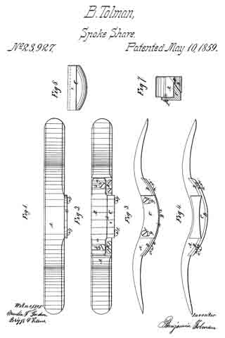
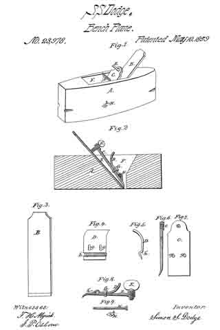
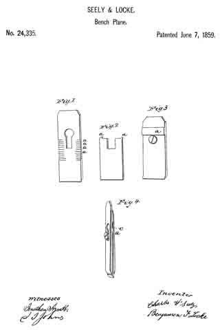
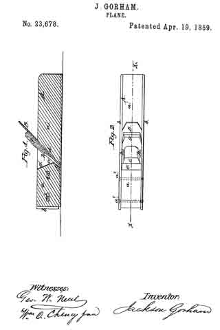
Figure 1, is a longitudinal vertical section of my invention taken in the line x, x, Fig. 2. Fig. 2, is a plan or top view of ditto.

Similar letters of reference indicate corresponding parts in the two figures.

This invention consists in having the stock of the plane formed of wood with metal sides and the front part of the wooden portion made adjustable by means of set screws, so that the “throat” may be enlarged and contracted at pleasure, as the nature of the work may require.

The invention is designed to facilitate the construction of planes and render them more perfect than those of ordinary construction.

To enable those skilled in the art to fully understand and construct my invention I will proceed to describe it.

A, represents the plane stock, which is formed of a wooden center a, a’, with a metal strip or plate b, at each side. The back part a’, of the wooden part of the stock is permanently attached to the metal plates b, b, but the front part a, is adjustable, that is to say, it is allowed to slide longitudinally between the plates b, b, and nearer to or farther from the part a’, of the central wooden portion as may be desired, — the part being secured at any desired point by set screws ax, ax.

The throat c, of the plane is formed between the parts a, a’, of the central wooden portion of the plane, the front end of the part a’, being inclined, as shown at d, and the back end of the part a, having a double inclined surface, as shown at e, f. This form of the adjoining ends of the parts a, a’, constitute the throat, and as the part a, is adjustable the throat it may be seen may be enlarged or contracted as desired.

The lower edges of the metal slides b, b, do not quite extend down to the bottom of the wooden portion a, a’, of the stock, and consequently the bottoms of the wooden portion a, a’, constitute the “sole” of the plane. The iron B, is of usual form and is fitted against the end d, of the part a’, and secured thereto by a wooden key or wedge g, which is driven behind flanches h, h, formed on the inner sides of the plates b, b, — the flanches being cast with the plates b, b.

From the above description it will be seen that the plane may be very readily constructed, much more so, than if made entirely of wood in the ordinary way. The throat c, is formed or made without difficulty and its orifice at the cutting edge of the iron B, may be contracted or enlarged as occasion may require. The plates b, b, may be of cast metal, and the central part a, a, may be of beech or other similar wood.

Having thus described my invention what I claim as new and desire to secure by Letters Patent, is,

Constructing the plane stock of a central wooden portion a, a’, secured between metal side plates b, b, provided with flanches h, h, the part a’, being permanently secured between the plates b, b, and the part a, rendered adjustable between said plates by set screws ax, ax, substantially as and for the purpose set forth.

JACKSON GORHAM.

Witnesses:
GEO.W. NEAL,
WM. O. CHENEY, Jun.

No. 23,927 – Spoke Shave (Benjamin Tolman) (1859)

[paiddownloads id=”81″]23927


UNITED STATES PATENT OFFICE.

_________________

BENJN. TOLMAN, OF PEMBROKE, MASSACHUSETTS, ASSIGNOR TO HIMSELF AND A. T. RAMSDELL, OF SAME PLACE.

SPOKE-SHAVE.

_________________

Specification of Letters Patent No. 23,927, dated May 10, 1859.

_________________

To all whom it may concern:

Be it known that I, BENJAMIN TOLMAN, of Pembroke, in the county of Plymouth and State of Massachusetts, have invented an Improved Spoke-Shave or Heel-Shave; and I do hereby declare that the same is fully described and represented in the following specification and the accompanying drawings, of which —

Figure 1, denotes a top view of it. Fig. 2, an underside view of it. Fig. 3, a front side view of it. Fig. 4, a rear side view of it. Fig. 5, a transverse and central section of it. Fig. 6, an underside view of its adjustable throat gage to be hereinafter described.

In the drawings, A, exhibits the stock or handle of the shave; B, the curved knife, while C, is the throat gage, the said knife and throat gage being constructed of metal. In spoke shaves or heel shaves as ordinarily constructed, the knife is furnished with “starts” or adjusting contrivances, which extend transversely through the handle, and cause the knife during the process of adjusting it, to be moved either toward or away from the stock. In consequence of this mode of arranging the adjustments, the knife, while the shave is being used, is very apt to be moved toward the stock or get out of place, for the great pressure employed to keep the tool in contact with the article to be shaved is borne mostly and directly by the knife and in such manner as to render the knife liable to be forced up to or toward the handle. In the construction of my improved shave I have avoided this liability of derangement of the knife. The two ears, a, a, of the knife, are not provided with starts to extend through the handle, but are formed so as to rest with broad bearings or surfaces upon flat surfaces or plates of metal, D, D, screwed or fastened lirmly to the stock, each of the said ears being provided with a slot, b, arranged transversely in it, and for the reception of one of two clamp screws, c, c, which is passed through it and screwed into the bearing plate, such clamp screw having its head projecting over the opposite sides of the slot in order that when screwed down firmly it shall confine the ear in place on the bearing piece. In connection with the said movabllie and adjustable knife, I employ an adjustable throat gage, C, which is formed as shown in the drawings, is fastened by screws f, f, to the front side of the stock. It also extends in front of the knife and between the latter and the stock, as shown in Fig. 5. The screws, f, f, pass respectively through elogated slots g, g, made in the adjustable gage C, the same being so arranged as to enable the gage C, to be moved in a direction at a right angle to that in which the knife is capable of being moved.

The object of adjusting the knife as described is to enable the cutting edge h, to be brought into a suitable position with respect to the rear edge of the bearing part, i, of the throat gage, for it will be observed that in proportion as the knife is worn down by the act of sharpening or grinding it, it will require to be moved forward. Furthermore, the object of making the throat gage adjustable is, to regulate the depth of cut or thickness of shaving to be taken by the knife.

From the above, it will be seen that the knife having been once adjusted and clamped firmly on its bearing plates cannot easily be thrown out of place while in operation, and besides this the adjustment of the distance between the knife and the throat gage can be made without disturbing the knife. As most of the pressure by which the tool is borne against an article while in the act of cutting the same, is borne by the knife, there is little or no danger of derangement of the throat gage.

I do not claim a shave made with a stationary knife and an adjustable gage; nor do I claim a shave as made with an adjustable knife and a stationary mouthpiece disposed in front of the knife, but what I do claim as my invention is —

An improved spoke shave, constructed substantially as herein before described, that is with an adjustable knife and an adjustable throat gage, arranged and applied to the stock, and so as to move with respect to one another as specined.

In testimony whereof I have hereunto set my signature this twenty eighth day of September, A. D. 1857.

BENJAMIN TOLMAN.

Witnesses:
ISAAC JOSLYN,
EVA LAMBERT.

No. 23,928 – Improved Bench Plane (William S. Loughborough) (1859)

[paiddownloads id=”82″]23928


UNITED STATES PATENT OFFICE.

_________________

W. S. LOUGHBOROUGH, OF ROCHESTER, NEW YORK.

IMPROVED BENCH-PLANE.

_________________

Specification forming part of Letters Patent No. 23,928, dated May 3, 1859.

_________________

To all whom it may concern:

Be it known that I, WM. S. LOUGHBOROUGH, of Rochester, in the county of Monroe and State of New York, have invented a new and useful Iron Fillister-Plane, the principles of which are applicable, with slight modifications, to panel-plows, match-planes, dados, rabbets, and to bench-planes; and I do hereby declare that the following is a full and exact description of its construction and operation, reference being had to the accompanying drawings, and to the letters of reference marked thereon.

Figure 1 is a side elevation. Fig. 2 is a plan of the race. Fig. 3 is a plan of the parallel fence F. Fig. 4 is an elevation ofthe reverse side of Fig. 1 without the handle, and showing the shape and position of the stop P, also of the spur M.

The nature of my invention consists, first, in the construction of an iron stock for fillisters, dados, rabbets, rnatch-planes, and panel-plows; second, in the construction of a parallel fence, F, for fillisters and match-planes; third, in the construction and arrangement of a stop, P, moving diagonally to the line of pressure upon it, the same being applicable to the dado and panchplow; fourth, in the application and arrangement of the spring-cap G, in combination with the screw 2 or any other adjustable or lined fulcrum; fifth, the combination of the adjusting-screw 1 with the bit B and spring-cap C; sixth, the application and arrangement of the spur M.

I construct the plane-stocks, as seen in Figs. 1 and 4, with an arch, N, which connects the face in front of the throat with that in the rear, and at the same time affording a cutting-edge to the bit B the full width of the face of the plane. The projection R governs the position of the bit. The screw 2 passes through the slot of the bit and into this projection, and the adjusting-screw 1 screws through the said projection and against the upper end of the bit B, so that by turning the said adjusting-screw up the edge of the bit is thrown below the face of the plane, causing it to cut a thicker shaving, and vice versa, whereby the operator is enabled to adjust the “cut” of the bit to the rnerest fraction, and in an instant.

The parallel fence F, I construct, as seen in Fig. 3, with the slots D, through which the screws Y pass, running out from the face of the fence at an angle of sixty degrees, more or less, so that when the nuts 4 and 5 are loosened to make changes one measurement only is required, for neither end can move up or back faster than the other when the screws Y are properly tilted to the slots D.

The stop P is made and arranged, as seen in Fig. 4, with the slot for the set-screw K, in this also running up diagonally from its face, so as to prevent any possibility of the downward pressure of the plane when it has worked to the desired depth from forcing the stop up, and thereby allow it to work too deep. It is kept in its proper position by the guide-pin U.

The handle H is cut to lit under the projection R, and the screw 7, Fig. 2, is put through the face of the plane and into the handle, which holds it firmly to its place.

The spur M, Figs. 2 and 4, is made of plate-steel and fitted into a dovetail seat, where it is held by the screw 6, which has a bevel or a countersunk head, one side of which is pressed against the spur when the screw is turned in.

The projections J are to allow the fence to be adjusted to the full width of the face of the plane. The rib X is to strengthen the arch N.

There may be a slip, V, of wood let into the fence F to prevent the edge of the bit from coming in contact with the iron when the bit is being taken out or replaced.

What I claim as my invention is —

1. The combination of the screw 2, (which takes effect in the projection R,) spring or yielding cap C, bit B, and screw 1, for the purpose of varying the cut of the bit, and at the same time and proportionally the space of the throat, the base of the bit B being the fulcrum upon which it swings when said changes are made, the said combination being applicable for the adjustment of the bit in all kinds of planes.

2. The adjustable parallel fence F, constructed with diagonal slots D for the set-screws Y, as and for the purpose specified, said fence being applicable to match-planes, and also the stop P, with the slot running up diagonally from the face, the set-screw K, and the guide-pin U keeping it in position, said stop being applicable to panel-plows and dados.

WM. S. LOUGHBOROUGH.

Witnesses:
CHARLES GILBERT,
RICHARD GILBERT.

No. 23,978 – Hand Plane (Simeon S. Dodge) (1859)

[paiddownloads id=”83″]23978


UNITED STATES PATENT OFFICE.

_________________

SIMEON S. DODGE, OF SUNAPEE, NEW HAMPSHIRE, ASSIGNOR TO HIMSELF, AND EDMUND BURKE, OF NEWPORT, NEW HAMPSHIRE.

HAND-PLANE.

_________________

Specification of Letters Patent No. 23,978, dated May 10, 1859.

_________________

To all whom it may concern:

Be it known that I, SIMEON S. DODGE, of Sunapee, in the county of Sullivan and State of New Hampshire, have invented a new and useful Improvement in Joiners’ Hand-Planes; and I do declare that the following is a full, clear, and exact description of the same, reference being had to the annexed drawings, making a part of this specification, in which —

Figure 1, is a prospective view of the plane with the improvements claimed by me. Fig. 2, is a sectional view of the same. Fig. 3, is a plane view of the cutter iron. Fig. 4, is a view of the curved adjustable cop-iron. Fig. 5, is a sectional view of the same. Fig. 6, is a sectional view of the top, or break iron. Fig. 7, is a plane view of the same. Fig. 8, is a sectional view of the adjustable cop iron and the break iron as adjusted for work. Fig. 9, is a view of the bolt and nuts by which the cop iron and break iron are adjusted and confined when in use.

The same letters represent corresponding parts in the various figures.

A, is the stock of the plane.

B, is the cutting iron by which the shaving is removed, and is constructed in its simplest form, as seen in Fig. 3.

C, is the cop, or break iron and is constructed substantially as seen in Figs. 6, and 7.

D, is the curved adjustable cop-iron, and is constructed as seen in Figs. 4: and 5, and is used for the purpose of adjusting the break iron C, and guiding the shaving through the mouth F, of the plane.

E, is a thumb screw which passes through the female screw e, in the break iron C, and serves to keep the latter in place, when properly adjusted for work.

G, represents one of two set screws which pass through the slots g, g, in the adjustable cop iron D, and penetrate the female screws g’, g’, in the break iron C.

H, is a bolt which passes through the stock A, in the groove h in the adjustable cop iron D.

h, is a nut on the side of the stock A, opposite to the head of the bolt H, by which the latter is confined.

In order to adjust the plane for work, the break iron C, is confined to the adjustable cop iron D, by means of the two set screws G, G, (only one of which is shown in the drawings) as seen in Fig. 8. Thus adjusted, the break iron C, and the adjustable cop iron D, are inserted in the mouth F, of the plane, in which they are confined in the right position by means of the bolt H, which passes through the groove h’, and is confined in place by the nut h. The cutter iron B, is then passed into the mouth F, and when properly set for work, is confined lirmly in place by the thumb screw E, which presses upon the upper part of the cutter iron B, bearing the lower edge of the break iron C, firmly down upon the lower portion of the cutter iron B, the bolt H, acting as a fulcrum upon which the break iron C, turns, The cutter iron B, thus adjusted for work, is seen in Fig. 2. By removing the pressure of the thumb screw E, the cutter iron B, may be easily removed, or adjusted for cutting a thicker or thinner shaving, as the work to be done may require.

It is well known that some kinds of timber to be wrought, have nearly an even and regular grain; other kinds have an uneven and irregular grain; and other kinds all knotty and shaky. Some kinds of timber are hard and tenacious; and others are soft and easily wrought. Consequently it becomes necessary that the plane should be adjusted so as to be able to work all kinds of timber with facility and without injury or waste. In working some kinds of timber a thick shaving may be taken off at a single stroke of the plane; and in working other kinds only a very thin shaving can be removed at a single stroke. In order to accommodate the break iron C, to the cutting iron B, so as to enable the latter to accomplish the various work required of it, I have out two slots g, g, in the adjustable cop D, through which the two set screws G, G, above described pass, the latter penetrating the female screws g, g, in the break iron C, as before stated. The slots g, g, permit the set screws G, G, when loosened, to pass freely up and down, thus enabling the operator to so adjust the break iron C, as to cut a thick or thin shaving, as the nature of the work may require, the adjustable cop iron D, being at the same time kept in place by the bolt H.

The advantages of my improvement, are its great simplicity, efficiency, and cheapness. The chip, or wedge, of the plane as ordinarily constructed, is entirely dispensed with. The cutting iron which, in my improved plane, is a plain piece of steel, or iron edged with steel, can be much more cheaply made; and when worn out, or broken, it can be readily removed and another substituted, without the expense of getting a new break iron each time the cutter iron is changed, or substituted. The cutting iron also can be more readily and easily removed from the stock when it requires to be sharpened, and more readily and easily adjusted for its work, than by any other device for the purpose heretofore known until my invention. It is not necessary for the operator to use a hammer about my improved plane. Thus the stock is preserved from the injury which it receives from the blows of the hammer in inserting, adjusting, confining, and removing the cutting iron, in and from it.

Having above fully described my improved hand plane, its construction, and mode of operation, what I have invented and desire to secure by Letters Patent, is —

1. The curved adjustable cop iron D, constructed and operating substantially as above described.

2. The combination of the adjustable cop iron D, with the bolt H, the set screws G, G, and the thumb screw E, and the break iron C, constructed and operating substantially as above described.

SIMEON S. DODGE.

Witnesses:
F. N. MYRIK,
I. P. OSBORN.

No. 24,335 – Securing The Bits Of Bench Planes (Charles W. Seely And Benjamin F. Locke) (1859)

[paiddownloads id=”84″]24335


UNITED STATES PATENT OFFICE.

_________________

CHAS. W. SEELY AND BENJ. F. LOCKE, OF WELLINGTON, OHIO.

MANNER OF SECURING THE BITS OF BENCH-PLANES.

_________________

Specification of Letters Patent No. 24,335, dated June 7, 1859.

_________________

To all whom it may concern:

Be it known that we, CHARLES W. SEELY and BENJAMIN F. LOCKE, of Wellington, in the county of Lorain and State of Ohio, have invented a new and Improved Plane-Bit for Planing Wood, and we do hereby declare that the following is a full and exact description thereof, reference being had to the accompanying drawings and the letters of reference marked thereon.

The nature of the invention consists in adjusting a steel bit between a cap and bed piece, which cap and bed piece are similar to the common cap and plane bit now generally used, and usually designated as the double plane bit. Our bit is manufactured entirely of steel and therefore we avoid the injurious effect produced upon steel, by the great heat to which it is necessary to subject it, to weld it upon iron; and thus we obtain a much finer and keener edged implement than can be obtained from the common method of manufacturing plane bits. Our bit also requires much less grinding than the common bit, and can be manufactured at less expense.

To enable others skilled in the art to make and use our invention, we proceed to describe its construction and operation.

This bit is manufactured of steel only, and is a thin plate varying from a sixteenth to an eighth of an inch in thickness, or thereabout, and of the usual width, with a notch in the middle of the upper end for the passage of the fastening screw. Each opposite corner of the notched end of the bit is turned down to form spurs to mesh into grooves or notches, in the bed piece, which see Figure “2” in the diagram letters “a a” which represent the steel bit and the corners.

The bed piece is represented by Fig. “1” of the diagram, is made of iron of the same width of the steel bit, and of the length of the common plane bit. The notches or grooves “a a” are for the spurs on the steel bit to mesh into, and are made about one-fourth the width of the bed piece from each edge thereof, and are exactly parallel. These and the spurs on the steel bit, are to prevent the bit from slipping up when force is applied for planing. The circular hole and notch in the bed piece is the same as in common use, and is for the entrance of the screw, by which the three pieces are fastened together as seen in Fig. “4”

The cap is made in the same manner, and like the common cap now in use, with the exception of a bar of iron just above the screw hole, and to be of the thickness of the steel bit, which is welded or riveted on the inner surface of the cap. This cross piece or bar is to prevent the cap from pressing upon the upper end of the steel bit, and thus prying apart the lower ends when the three are joined by the screw; instead of this cross piece or bar any means of making an elevation on the same surface of the cap may be used. This cap with the cross piece or bar is represented in Fig. “3” letter “a” and is also seen in Fig. “4” letter “c” The mashing of the spurs on the steel bit into the grooves on the bed piece is seen at “a” Fig. “4.”

We do not not claim broadly the interposition of a steel planing bit between a cap and bed piece, as this already has been done, but

What we claim, is —

Stopping the upper end of the interposed bit below the screw, and upsetting it, so as to catch into the cross serrations in the bed piece, as set forth.

CHARLES W. SEELY.
BENJAMIN F. LOCKE.

Witnesses:
JONATHAN ARNATT,
J. L. HUTCHINSON.

No. 24,623 – Carriage Wheel Rim Plane (Reuben Fretz) (1859)

[paiddownloads id=”85″]24623


UNITED STATES PATENT OFFICE.

_________________

REUBEN FRETZ, OF MONTVILLE TOWNSHIP, OHIO.

MACHINE FOR FINISHING THE EXTERIOR OF RIMS OF CARRIAGE-WHEELS.

_________________

Specification of Letters Patent No. 24,623, dated July 5, 1859.

_________________

To all whom it may concern:

Be it known that I, REUBEN FRETZ, of the township of Montville, in the county of Medina and State of Ohio, have invented a new and useful. Gage-Plane for Dressing the Edges of Carriage-Wheels or other Circles and Curves; and I do hereby declare that the same is described and represented in the following specification and drawings.

To enable others skilled in the art to make and use iny invention I will proceed to describe its construction and operation referring to the drawings in which the same letters indicate like parts in each of the figures.

Figure 1, is an elevation of the back side of my gage plane, Fig. 2, is a. plan or top view, Fig. 3, is a plan of the under side.

The nature of my invention for dressing the edges of carriage wheels or other circles and curves, consists in combining in the arm that gages the plane devices for varying the height of the fulcrum or center, with devices for varying its length, so as to enable the operator to dress his wheel straight or square across the edge to fit the tire. Also in making the arm which guides the plane to vibrate in the plane stock, so as to adjust and fasten it as may be desired. And in arranging some screws. to adjust the bits to suit circles of different sizes.

In the accompanying drawings A, is the top of the stock and B the bottom both of which are made in the form shown in the drawing, and fastened together by the bolts C, C. The top A, has the handle D, and pin E, fastened in it, for the operator to take hold of when he works the plane. F, is the spur iron or bit inade in the form shown in the drawing and fitted to a hole in the top A, where it is held by the wedge F’, its lower end being fitted to a score in the side of the bottom B. And to hold it firmly in the score the edges are beveled and it is fitted to a dovetailed score in the piece of metal G, fastened to the bottom B, with screws as shown in the drawing. The lower end of this spur bit is V-shaped to cut a score and sever the wood in advance of the plane bit or iron H, which is fitted to a score in the side of the bottom B, and passes up through the top A, and is fastened by the wedge H’; and to prevent the side of the stock from wearing between the bits F, and H, it is faced with a piece of metal I; and the screws J, J, are arranged to act against the bits F, and H, so as to adjust them to cut circles of different sizes. In order to enable the operator to work this plane in the arc of a circle or around the rim of a wheel, I connect it to a pin or pivot, set in the center of the circle or hub of the wheel by a compound arm which consists of the bar K, fitted to a mortise in the top A, and arranged to vibrate on the screw L, and semicircle M, which is also fastened to the top A, and there is a piece of metal N, fastened to the under side of the bar K, and provided with a set screw O, to act against the circle M, and hold the bar K, in the position desired.

The standards P, P, are fastened in the top of the bar K; and the bar Q, is fitted or provided with a slot, so as to traverse both horizontally and perpendicularly on the standards P, P; and when adjusted in the position desired, it may be fastened by the clamping screw R, which passes through both arms of the bar Q, and is arranged to traverse in slots in the arms of the bar Q, as it is traversed horizontally on the standards P, P. The end of the bar Q, is perforated at S, and bushed with a piece of metal fitted to the pivot set in the center of the circle or hub of the wheel to be dressed. The wood is cut away in front of the bit H and enlarged toward the outside of the bottom, B to let the chips escape which are cnt by the bit, H.

The plane being constructed and completed as above described and the rim of the wheel to be dressed being properly fastened to the spokes and placed in a horizontal position, and a pivot set in the hub for the end of the bar Q, to work on; and the bar Q, adjusted on the standards P, P, so as bring the plane a proper distance from the center, with its top level or the inner edge little the lowest. The plane is now worked and the edge of the wheel dressed a quarter of an inch deep all around, and then the bar Q, inust be raised a quarter of an inch on the standards P, P, when the rim may be dressed a quarter of an inch deeper; and so on until it is pressed entirely across the edge as desired.

The rims of wheels may be dressed far better and quicker and with far less labor with my plane than can be with an ordinary drawing knife. And besides it will be far less labor to fit and set the tire upon them.

I believe I have described and represented my invention, so as to enable any person skilled in the art to make and use it. I will now state what I desire to secure by Letters Patent.

1. I claim combining in the arm that gages the plane devices for varying the height of the radial arm, with the devices for varying its length so as to enable the operator to dress a wheel straight or square across the edge substantially as described.

2. I claim making the arm or bar K, which guides the plane in the arc of a circle, to vibrate in the stock, so as to adjust and fasten it in the position desired.

REUBEN FRETZ.

Witnesses:
W. L. NICHOLLS,
SIDNEY CULVER.