No. 31,707 – Bevel Attachment For Bench Planes (Leonard O. Fairbanks) (1861)
UNITED STATES PATENT OFFICE.
_________________
LEONARD O. FAIRBANKS, OF NASHUA, NEW HAMPSHIRE.
BEVEL ATTACHMENT FOR BENCH-PLANES.
_________________
Specification of Letters Patent No. 31,707, dated March 19, 1861.
_________________
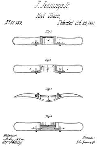
To all whom it may concern:
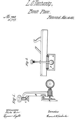
Be it known that I, LEONARD O. FAIRBANKS, of the city of Nashua, county of Hillsboro, and State of New Hampshire, have invented a new and useful Square and Bevel Attachment for Planes or other Bench-Tools; and I do declare the following is a fulland exact description thereof, reference being had to the annexed drawings.
The object of my invention is to enable persons using the ordinary bench planes to produce a square or any required bevel with certainty and despatch, Without the extraneous aid of square and bevels.
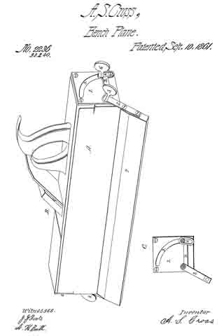
The nature of my invention consists in attaching to bench planes a clamp with an adjustable guide, and is constructed as follows: I construct a clamp A, Figure 1, of such size as will readily receive between its lugs B and binding screw C the diliierent sizes of planes, in such a manner that will secure the plane of the lugs in the square of the plane, as shown in perspective (Fig. 2). To the lugs is connected a guide plate D whose proportion is such as to secure the steadiness of a guide. At the foot of the upright A and at right angles with the face of the guide D is an adjjusting screw H which is operated by a stationary nut F. When the clamp is attached to the plane the guide plate is adjusted either at right angles with the plane stock, for the purpose of obtaining a square edge, or set at any required angle, for a bevel, by means of the adjusting nut F.
What I claim as my invention and for which I desire to secure Letters Patent is —
The attaching of an adjustable guide to the stocks of bench planes, substantially in the manner and for the purpose set forth.
LEONARD O. FAIRBANKS.
Witnesses:
O. D. MILLER,
ISAAC SPALDING.