No. 221,763 – Improvement In Grooving-Irons (John W. Ammons) (1879)
UNITED STATES PATENT OFFICE.
_________________
JOHN W. AMMONS, OF COLUMBIA, MISSOURI, ASSIGNOR TO HIMSELF AND JOHN P. HORNER, OF SAME PLACE.
IMPROVEMENT IN GROOVING-IRONS.
_________________
Specification forming part of Letters Patent No. 221,763, dated November 18, 1879; application filed September 15, 1879.
_________________
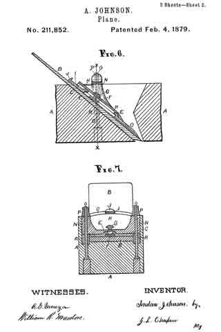
To all whom it may concern:
Be it known that I, JOHN W. AMMONS, of Columbia, in the county of Boone and State of Missouri, have invented a new and Improved Grooving-Iron, of which the following is a specification.
My invention relates to improvements in the tongued irons or bits used in grooving-planes.
Heretofore the form of these irons has been such as to leave the corners of the groove sharp. This is objectionable on account of their liability to break off when the tongue is forced in and carried back into the groove, whence they have to be removed at a great expense of time and trouble; or if allowed to remain they interfere with the making of a good joint. To prevent this with the present tools, it is the habit of many workmen to chamfer off the corners with an ordinary rabbeting-plane; but this requires the use of another tool and the expenditure of valuable time.
The object of my invention is to provide a plane-iron which will chamfer off the outer corners of the groove simultaneously with the planing of the groove.
The invention consists in a plate with beveled cutting-edges, a slot, and a longitudinal groove, in combination with a grooving-iron provided with a cutting-edge, as hereinafter described.
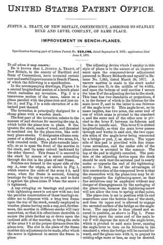
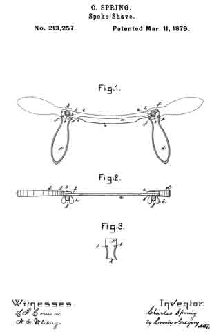
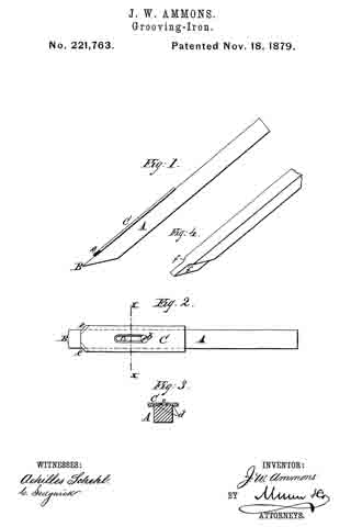
In the accompanying drawings, Figure 1 is a side elevation of my improved iron. Fig. 2 is a plan view of the same. Fig. 3 is a cross-section on line x x of Fig. 2; and Fig. 4 represents, in perspective, a modified construction of the iron.
Similar letters of reference indicate corresponding parts.
Referring to the drawings, A is the grooving bit or iron, made of a rectangular bar of steel, with cutting-edge B. On the upper side of iron A is placed a flat plate of steel, C, which is secured to the bit by a set-screw, b, passed down through the slot c in the plate into a threaded hole in the bit.
In the under side of the plate is a shallow longitudinal groove, d, sufliciently wide to receive the bit, as shown in Fig. 3. This groove d, together with the set-screw b, connects the plate C rigidly with the bit A, so that the plate C can neither rise nor lose its parallel adjustment with relation to the bit.
At the lower end of plate C the corners are chamfered or beveled off at any suitable angle, and the corners are given sharp cutting-edges e e.
The plate C is designed to extend one-sixteenth of an inch beyond the sides of the bit, so that the angular cutting-edges e e will come in contact with the sides of the groove cut by the bit. The object of this arrangement is to chamfer off the upper corners of the sides of the grooves at the same time the groove is planed, so as to enable the flooring-tongue to be entered into the groove without trouble, and without liability of breaking off the corners of the groove and forcing the splinters in the groove, as before mentioned.
The lower end of plate C forms the shoulders of the plane-iron to limit the depth of the groove.
In Fig. 4 is shown a bit with the shoulders forming a part thereof, in the usual manner. Herein the front lower edges, f f, are cut off at an angle and sharpened to an edge, the same as the edges e e of the plate C.
Both forms of plane-irons operate in the same way to chamfer off the corners of the sides of the groove; but the arrangement first described offers superior facilities for keeping the bit in good order, on account of the ease with which the edges e e can be sharpened.
Having thus fully described my invention, I claim as new and desire to secure by Letters Patent —
The plate C, having beveled cutting-edges e e at a suitable angle, and provided with a longitudinal groove, d, and slot c, and set-screw b, in combination with the grooving-iron having cutting-edge B, for the purpose of chamfering off the corners of the sides of the grooves, substantially as described.
JOHN W. AMMONS.
Witnesses:
F. D. EVANS,
I. O. HOCKADAY.