No. 250,007 – Bench-Plane (George F. Sawyer) (1881)
[paiddownloads id=”317″]250007


UNITED STATES PATENT OFFICE.

_________________

GEORGE F. SAWYER, OF LIBERTY, TEXAS.

BENCH-PLANE.

_________________

SPECIFICATION forming part of Letters Patent No. 250,007, dated November 22, 1881.
Application filed July 5, 1881. (No model.)

_________________

To all whom it may concern:

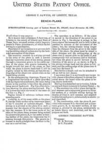
Be it known that I, GEORGE F. SAWYER, of Liberty, in the county of Liberty and State of Texas, have invented certain useful Improvements in Plane Attachments, of which the following is a specification.

The object of my invention is to prevent dulling the cutting-edge of a plane-iron by the backward movements of the plane.

The invention consists in a stirrup pivoted to the sides of the plane in such a manner that the transverse piece of the stirrup passes through a transverse groove in the under surface of the plane, this groove increasing in height toward the rear of the plane, so that when the plane is drawn backward it will be slightly raised by this stirrup, so that the cutting-edge of the plane-iron cannot slide on the board being planed.

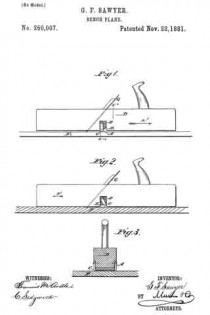
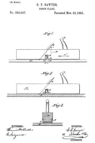
In the accompanying drawings, Figure 1 is a longitudinal elevation of a plane provided with my improved attachment, the same being shown in the position it has when the plane is being moved backward. Fig. 2 is a like elevation, showing the plane moving forward. Fig. 3 is a cross-sectional elevation of the same on the line x x, Fig. 1.

Similar letters of reference indicate corresponding parts.

A stirrup, A, of the same width as the plane B, has the outer surface of its transverse piece or bar C rounded or cylinder-shaped. This stirrup A is pivoted to the plane B in such a manner that the shanks of the stirrup extend into the recesses D in the lower parts of the sides of the plane, these recesses being united by a transverse groove, E, in the under or bearing surface of the plane, the transverse bar C passing through this groove. The groove increases in depth or height from the front to the rear on a curved line.

The operation is as follows: If the plane is moved in the direction of the arrow x’, as shown in Fig. 1, the stirrup A swings to the front edge of the recesses D, and is held in that position on account of the movement of the plane; but, the stirrup-shanks being longer than the distance from the pivot to the under side of the plane, the plane must be raised a short distance and the cutting-edge of the plane-iron G cannot slide on the board F, and consequently will not become dull or blunted; but when the plane is moved forward in the direction of the arrow y’, as shown in Fig. 2, the stirrup swings back and the plane is lowered, and the cutting-edge of the plane-iron G cuts into the board F.

This device is simple and can be attached to old as well as new planes.

I am aware that it is not broadly new to provide planes with rollers adapted to elevate the cutter above the board when the plane is being drawn backward.

Having thus described my invention, I claim as new and desire to secure by Letters Patent —

1. The combination, with a plane having lateral recesses and a transverse groove in its under surface, of a suitable stirrup having its shanks pivoted in said recesses and adapted to slide into said groove, substantially as shown and described.

2. The combination, with the plane B, provided with recesses D in the sides and a transverse groove, E, in the under surface, of the stirrup A, pivoted to the plane, substantially as herein shown and described, and for the purpose set forth.

GEORGE FREDERIC SAWYER.

Witnesses:
W. B. TAYLOR,
D. C. PALMER.

No. 249,097 – Shave (Henry P. Roberts) (1881)

[paiddownloads id=”316″]249097


UNITED STATES PATENT OFFICE.

_________________

HENRY P. ROBERTS, OF JAMESTOWN, N. Y., ASSIGNOR OF THREE-FOURTHS TO THE HORTON MANUFACTURING COMPANY, OF SAME PLACE.

SHAVE.

_________________

SPECIFICATION forming part of Letters Patent No. 249,097, dated November 1, 1881.
Application filed June 1, 1881. (No model.)

_________________

To all whom it may concern:

Be it known that I, HENRY P. ROBERTS, a citizen of the United States, residing at Jamestown, in the county of Chautauqua and State of New York, have invented certain new and useful Improvements in Shaves; and I do hereby declare that the following is a full, clear, and exact description of the invention, which will enable others skilled in the art to which it appertains to make and use the same, reference being had to the accompanying drawings, and to the letters of reference marked thereon, which form a part of this specification.

The object of this invention is to combine a gage or friction roller with a cutting edge or blade.

The principle of my invention can be shown in a heel-shave by which any of the ordinary-shaped heels may be operated upon, the tool adjusted to cut thin shavings of leather, and the shavings moved rapidly away from the knife-edge, to prevent clogging of the shavings-passage, and the tool can also be used upon wood as an ordinary spokeshave.

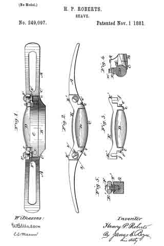
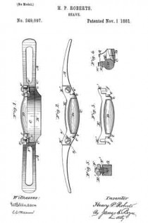
In the accompanying drawings, Figure 1 is a bottom view of a spoke or heel shave with my improvement thereon. Fig. 2 is a front view thereof. Fig. 3 is a view of the gage-roller and the frame thereof, detached. Fig. 4 is a transverse section through the middle of the roller, its supporting-frame, and the knife-blade, with its frame; and Fig. 5 is a section on line x x of Fig. 2.

The letter A represents the handle of the tool, which is curved at the center and recessed inwardly from its front edge, to receive the knife and gage-roller, the two parts of the handle being conneoted in one piece by the curved bridge B.

Immediately in front of the bridge is located the knife-blade C, curved to conform to the shape of the lower surface of the bridge, and secured to the handle by screws c. The cutting-edge of the knife is turned outwardly and projects somewhat forward of the shanks C’, by which said blade is attached to the handle.

Immediately above and partly in front of the edge of the knife is arranged a gage-roller, D, which corresponds with the shape of the knife, and in this case it tapers from its middle toward each end in such a manner that the longitudinal curve of its surface corresponds with the curve of the edge of the knife; but if it should be combined with a straight knife, it would be cylindrical in shape. This gage-roller D is mounted in an adjustable frame, E, between the downwardly-projecting lugs e, on which the roller is pivoted on screw-pivots e’. The ends E’ of the frame are provided with open slots f, through which pass screws F to secure said frame to the handle, the slots permitting either an upward or downward adjustment of the frame and roller, to bring said roller in such relation to the knife as to regulate the cut thereof as desired.

It will be observed that, owing to the curved shape of the knife, a very small portion of its edge may be brought in contact with the surface acted upon, if said surface is nearly flat, and that a heel of any of the ordinary shapes, either curved or straight, may be trimmed by the tool. The roller revolves as the tool advances, and the cut shavings coming in contact with the roller, their passage is facilitated through the opening between the roller and knife.

While the main functions of the gage-roller are to regulate the out of the knife, to remove friction and facilitate the passage of the shavings, it can be adjusted also to compensate for the wearing away of the edge of the knife. The adjustment can be made either by placing washers between the ends E’ of the roller-frame E and the frame of the blade C and removing these washers as fast as the blade wears away, or by supporting and clamping each end of the roller-frame between the heads of two screws, as shown in Figs. 1 and 5. In these figures, F’ represents the screws, inserted adjustably in the frame A. The flat head of said screws is hollow, and screw-tapped internally to receive the clamping-screws F, so that whatever may be the width of the blade C the roller D can be made to follow its edge, and the frame of said roller can be secured at each end.

I do not limit the use of my invention to heel or spoke shaves, as it is applicable to other cutting-instruments-for instance, carpenters’ planes.

Having now described my invention what I claim is —

1. The combination , with the handle, recessed as described, of the curved knife C, and the gage-roller tapered from its middle to its ends to conform to the curves of said knife, substantially as and for the purpose set forth.

2. The combination, with the recessed handle having the curved knife C secured thereto, of the roller D, arranged above said knife and mounted in an adjustable frame, E, substantially as described.

3. The combination with the handle, recessed as described, and having secured thereto the curved knife C, of the roller D, mounted in an adjustable frame, E, having the lugs e, between which the roller is pivoted, and between which the edge of the knife extends, substantially as described.

4. The combination of the centrally-curved handle, curved knife C, tapering roller D, and frame E, with adjustable hollow screws F’ and clamping-screws F, substantially as and for the purpose described.

In testimony that I claim the foregoing as my own I have hereto affixed my signature in presence of two witnesses.

HENRY P. ROBERTS.

Witnesses:
JAMES I. FOWLER,
WILLIAM K. VANDERGRIFT.

No. 245,093 – One-Hand Plane (Isaac Reeder) (1881)

[paiddownloads id=”315″]245093


UNITED STATES PATENT OFFICE.

_________________

ISAAC REEDER, OF PHILADELPHIA, PENNSYLVANIA, ASSIGNOR OF ONE-HALF TO ROBERT S. DUFF, OF SAME PLACE.

ONE-HAND PLANE.

_________________

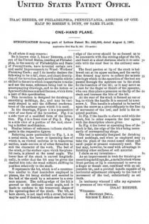
SPECIFICATION forming part of Letters Patent No. 245,093, dated August 2, 1881.
Application filed May 26, 1881. (No model.)

_________________

To all whom it may concern:

Be it known that I, ISAAC REEDER, a citizen of the United States,residing at Philadelphia, in the county of Philadelphia and State of Pennsylvania, have invented certain new and useful Improvements in Wood-Workers’ Finishing-Tools; and I do hereby declare the following to be a full, clear, and exact description of the invention, such as will enable others skilled in the art to which it appertains to make and use the same, reference being had to the accompanying drawings, and to the letters or figures of reference marked thereon, which form a part of this specification.

This invention is designed for finishing or smoothing moldings, &c., and may be variously shaped to suit the different conformations of the surfaces upon which it is used.

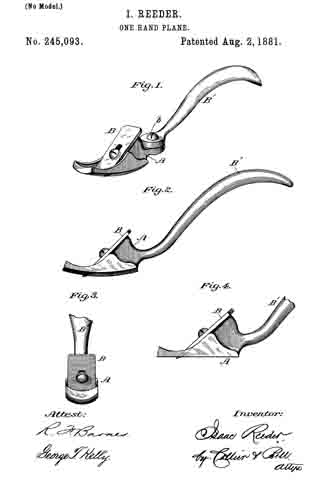
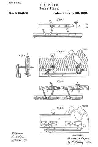
In the drawings, Figure 1 is a perspective view of one form of the invention. Fig. 2 is a side view of a niodided form of the invention. Fig. 3 is a front view of Fig. 2. Fig. 4 is a side view of a portion of the tool, showing a further modification.

Similar letters of reference indicate similar parts in the respective figures.

Referring more particularly to Fig. 1, A is a metal stock, the lower or operating face of which is, as viewed endwise or in transverse section, made convex or of other formation to suit the character of the work. The bed of the stock, or the surface upon which the plane-bit rests, is placed at the usual angle. The lower face of the stock is curved longitudinally, in order that the bit may be given the desired bite into the wood without shifting its position relatively to the stock.

B represents the bit, which is of a construction similar to that heretofore employed in planes, the bit being slotted and secured to the bed of the stock by a set-screw in a common manner. The cutting-edge of the bit is ground to the ordinary acute angle, and is made to conform to the transverse shape of the operating-face of the stock. The bit, as here shown, is not used. with a cover, but one may be used if desired, in which case the lower edge of the cover should be so formed as to be concentric with the cutting-edge of the bit, and fixed at a short distance above it to coincide with the steel face in the ordinary manner.

The front portion or lip of the stock is hollowed out at its upper surface, and the cavity thus formed may serve to collect the minute shavings which in the operation of the tool are passed through the aperture cut in the stock for the insertion of the bit; or it may serve as a rest for the finger or thumb of the operator, who can thus place a pressure on the lip of the stock and increase the bite of the bit.

At the rear of the stock is formed an ear or lug, to which the handle B is secured by a set-screw, b. This handle is adapted to be moved upon the screw as a pivot obliquely to the line of movement of the tool, and held in the required position.

In Fig. 2 the handle is shown solid with the stock, but in other respects the tool agrees with the description above given.

In Fig. 4 the lower or operating face of the stock is flat, the edge of the bit a, being necessarily of corresponding shape.

The tool is specially designed for finishing wood moldings, and when so employed may take the place of the round-nosed chisel and sand-paper at present commonly used. The tool may, however, be used with advantage in finishing other surfaces of soft material.

I claim as my invention —

As an improvement in tools for finishing or smoothing moldings, &c., a metallic stock whose front portion or lip is constructed to serve as a finger or thumb rest, combined with an adjustable bit, and a pivoted handle capable of horizontal adjustment obliquely to the line of movement of the tool, substantially as set forth.

In testimony whereof I affix my signature in presence of two witnesses.

ISAAC REEDER.

Witnesses:
J. SNOWDEN BELL,
GEORGE T. KELLY.

No. 243,398 – Bench-Plane (Samuel A. Piper) (1881)

[paiddownloads id=”314″]243398


UNITED STATES PATENT OFFICE.

_________________

SAMUEL A. PIPER, OF NEWTON, MASSACHUSETTS.

BENCH-PLANE.

_________________

SPECIFICATION forming part of Letters Patent No. 243,398, dated June 28, 1881.
Application filed May 3, 1881. (No model.)

_________________

To all whom it may concern:

Be it known that I, SAMUEL A. PIPER, of Newton, of the county of Middlesex and State of Massachusetts, have invented a new and useful Improvement in Plow or Grooving Planes; and I do hereby declare the same to be described in the following specification and represented in the accompanying drawings, of which —

Figure 1 is a top view, Fig. 2 a longitudinal section, Fig. 3 a horizontal section, and Fig. 4 a transverse section, of the plane as open. Fig. 5 is avertical section taken through its depth or lower gage.

The nature of my invention is defined by the claims hereinafter presented.

The grooving-plane, as described, has either or each of its gages connected with the stock by means of parallel links jointed to both, and such stock and gage are recessed to receive, when closed together, the links, and are provided with a clamping arc and screw, the whole enabling the gage to be readily adapted in parallelism with and to different distances from the stock and its cutter or plane iron, as occasion may require. The invention admits of the plane being materially reduced in width by closing the width-gage upon the stock, in which case their connections will not project beyond that side of the stock which is opposite to the one against which the gage may rest.

In the drawings, A denotes the stock; B, its handle; C D, its throat-plates; E, its chisel or cutter, and F the holding-wedge of the latter.

G is the width-gage, and H the depth-gage. Each of the said gages is connected with the stock by two parallel links, I I, pivoted or hinged at their ends to the gage and stock, there being within the said gage and stock recesses K, as shown, to receive the links when the gage is closed against the stock. There is also pivoted or hinged to the gage a circular curved arc or bar, L, which goes or slides freely into or through the stock, which is provided with a clarnp-screw, M, to act against and clamp the arc in position.

I claim —

1. In a plow or grooving plane, either or each of its gages connected with the stock by parallel links pivoted to such stock and gage, in combination with such stock and gage, recessed to receive, when they are closed together, the said links, and provided with a clamping are and screw for holding the gage in position, all being substantially as set forth.

2. In a plow or grooving plane, either or each of the gages connected with the stock by parallel links pivoted to such stock and gage, in combination with a clamping are and screw adapted to the gage and stock and to each other, substantially as set forth.

S. A. PIPER.

Witnesses:
CHARLES ELLIS,
ADELA M. ELLIS.

No. 242,740 – Flexible-Faced Plane (Leonard Bailey) (1881)

[paiddownloads id=”313″]242740


UNITED STATES PATENT OFFICE.

_________________

LEONARD BAILEY, OF HARTFORD, CONNECTICUT.

FLEXIBLE-FACED PLANE.

_________________

SPECIFICATION forming part of Letters Patent No. 242,740, dated June 14, 1881.
Application filed November 13, 1880. (No model.)

_________________

To all whom it may concern:

Beit known that I, LEONARD BAILEY, of Hartford, in the State of Connecticut, have invented certain Improvements in Flexible-Faced Planes, of which the following is a specification.

My invention relates to that class of planes in which the face is made flexible, so that by means of a screw or equivalent device it may be adapted to concave or convex surfaces of different degrees of curvature; and it consists in improvements upon these planes, as now constructed, in four particulars.

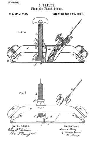
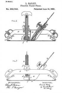
In the drawings, I have shown in Figure 1 a side elevation of a plane embodying my improvements, and in Fig. 2 a longitudinal section of the same.

The first part of my invention relates to the screw for regulating the degree of curvature of the face, and more especially to the method of attaching it to the stock, so that it shall be capable of adjustment in case of wear by use.

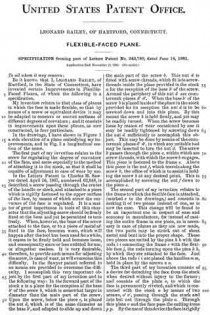
In the Letters Patent to Charles H. Sawyer dated April 16, 1867, numbered 63,948, is described a screw passing through the center of the handle or stock, and attached to a piece which is rigidly fastened to the upper surface of the face, by means of which screw the curvature of the face is regulated. It is a matter of great importance in tools of this character that the adjusting-screw should be firmly fixed at the base and yet be permitted to turn freely. When, however, the base of the screw attached to the face, or to a piece of metal affixed to the face, becomes worn, which will happen after the tool has been used for a while, it ceases to be firmly held and becomes loose, and consequently more or less unfitted for use, or altogether useless. It is very desirable, therefore, to provide such means for adjusting the screw, in case of wear, as will overcome this difticulty. In the Sawyer patent referred to no means are provided to overcome the difficulty. I accomplish this very important object by the first part of my invention and in the following way: In the forward part of the stock a is a place for the reception of the base b’ of the screw b, which is somewhat larger in diameter than the main part of the screw. Upon the screw, below the piece c, is placed the nut d, which is of the same diameter as the base b’, and adapted to slide up and down the main part of the screw b. This nut d is fitted with screw-threads, which fit into screw-threads inside the place provided in the stock a for the reception of the base b’ of the screw. Around the periphery of this nut d are countersunk places d’ d’. When the base b’ of the screw b is placed inside of the place in the stock provided for its reception the nut d is to be screwed down and into this place. By this means the screw b is held firmly, and yet may be readily turned. When the screw becomes loose by reason of wear occasioned by use it may be readily tightened by screwing down the nut d sufficiently to accomplish this object. This may be done by means of the countersunk places d’ d’, in which any suitable tool may be inserted to turn the nut d. The screw b passes through the piece c, within which are screw-threads, with which the screw b engages. This piece is fastened to the frame e. Above this piece is the nut f, which travels along the screw b, the office of which is to assist in holding the screw b at any desired point. This is accomplished by screwing the nut f down to the piece c.

The second part of my invention relates to the frame to which the flexible face is attached, (marked e in the drawings,) and consists in making it of two pieces instead of one, as is now the case. This change will be found to be an important one in respect of ease and economy in manufacture, for instead of casting the entire frame in one piece, as is necessary in case of planes as they are now made, the two parts may be struck out of sheet metal and bent into the proper shape. These two pieces are united by the pins h h, with the rods i i connecting the frame e with the flexible face j, the rods turning upon the pins k k, by which they are attached to the face. Just above the rods i i are placed the handles m m, held in place by the screws n n.

The third part of my invention consists of a device for detaching the face from the stock when desired without injury to the former; and consists of the plate o, to which the face is permanently riveted, and which is connected with the stock a by means of two screws, o’ o’, passing through the stock and into but not through the plate o. Through this plate o and the face pass the cutting-irons p p. By the use of this device the face is rigidly attached to the frame, but can be easily detached by removing the screws o’ o’ without in any way injuring the face or affecting its smoothness, which it is of the utmost importance to preserve, and which would be impaired if the face were fastened directly to the frame or stock by means of screws passing through the face, as is now generally the case. This part of my invention is adapted to all classes of planes.

I am aware that in the Letters Patent to Samuel D. Sargent, dated June 17, 1879, and numbered 216,577, a transverse recess adjacent to the throat and attached to the stock, and an independent throat-piece fitted to said recess and attached to the face, are described and shown; but my invention, just described, differs from that, inasmuch as the plate o is not a throat-piece, and has no other office or use than to attach the face to the stock in such manner as that it may be readily detached, and its mode of attachment to the stock is entirely different.

The fourth part of my invention consists in providing a head, q, in place of a crank, such as is used by Sawyer, as described by him in his said Letters Patent, for the purpose of turning the screw b, and an improved method of attaching this head to the screw, which is done by inserting the head in the slot r in the upper end of the screw b and holding the head in place by the screw s. By this means the screw b may be more readily turned, and also the head may be more easily attached or detached, as desired.

What I claim, and desire to secure by Letters Patent, is —

1. The combination, with flexible face j, piece c, stock a, and the frame to which they are attached, of screw b, having flange b’, and nut or collar d, which engages with a recessed part of said stock and operates to hold said stock and screw together, substantially as set forth.

2. A plane-frame consisting of two corresponding sheet-metal side plates, which may be stamped or struck up by the same die, said plates being fastened at their ends by cross pins or rods, substantially as set forth.

LEONARD BAILEY.

Witnesses:
HENRY E. TAINTOR,
EDWARD B. BENNETT.

No. 240,076 – Spokeshave (Louis Bauer) (1881)

[paiddownloads id=”312″]240076


UNITED STATES PATENT OFFICE.

_________________

LOUIS BAUER, OF SAN FRANCISCO, CALIFORNIA.

SPOKESHAVE.

_________________

SPECIFICATION forming part of Letters Patent No. 240,076, dated April 12, 1881.
Application filed December 27, 1880. (No model.)

_________________

To all whom it may concern:

Be it known that I, LOUIS BAUER, of the city and county of San Francisco, State of California, have invented an Improved Spoke-shave; and I hereby declare the following to be a full, clear, and exact description thereof.

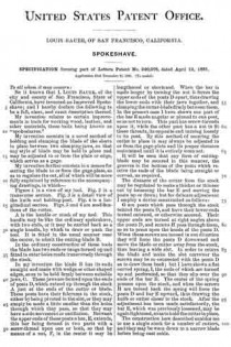
My invention relates to certain improvements in tools for working wood, leather, and other materials, these tools being known as “spokeshaves.”

My invention consists in a novel method of holding and clamping the blade of the shave in place between two clamping-jaws, so that any style of blade may be held in place and may be adjusted to or from the plate or edge, which serves as a gage.

My invention further consists in a means for setting the blade to or from the gage-plate, so as to regulate the cut, all of which will be more fully explained by reference to the accompanying drawings, in which —

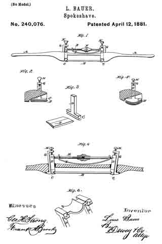
Figure 1 is a view of my tool. Fig. 2 is a transverse section. Fig. 3 is a detail view of the knife and holding-post. Fig. 4 is a longitudinal section. Figs. 5 and 6 are modifications of the cutter.

A is the handle or stock of my tool. This handle may be like the ordinary spokeshave, with two ends, or it may be carried back as a single handle, by which to draw or push the tool. It is fitted in the usual manner near the center, to admit the cutting-blade B.

In the ordinary construction of these tools the blade has two ends or tangs turned up and fitted to enter holes made transversely through the stock.

In my invention the blade B has its ends straight and made with wedge or other shaped edges, so as to be held firmly between suitable jaws, C. These jaws are formed upon the ends of posts D, which extend up through the stock A just at the ends of the cutter or blade.

These posts have their fulcrums in the stock, either by being pivoted in the slot, or they may simply be made a little smaller than the holes through which they pass, so that they may have a side movement or oscillation. Between the upper ends of these posts a bar, E, extends, this bar being formed in two parts with a screw-thread upon one or both, so that by means of a nut, F, in the center it may be lengthened or shortened. When the bar is made longer by turning the nut it forces the upper ends of the posts D apart, thus drawing the lower ends with their jaws together, and clamping the cutter-blade firmly between them. In the present case I have shown one part of the bar E made angular or pinned to one post, so as not to turn. This part has screw-threads upon it, while the other part has a nut to fit these threads, its opposite end turning loosely in its post. By this method of securing the cutter in place it may always be adjusted to or from the gage-plate and its proper distance maintained until it is entirely worn out.

It will be seen that any form of cutting-blade may be secured in this manner, the grooves in the bottom of the posts which receive the ends of the blade being straight or curved, as required.

The distance of the cutter from the stock may be regulated to make a thicker or thinner out by loosening the bar E and moving the posts up or down; but for delicate adjustment I employ a device constructed as follows:

G are posts which pass through the stock behind the posts D, and have their lower ends turned outward, or otherwise secured. Their upper ends are turned at right angles above the posts D, and screws H pass through them, so as to press upon the heads of the posts D. When these screws are turned in one direction they will force the posts D downward and move the blade or cutter away from the stock, thus leaving a wide slot. In order to return the blade and make the slot narrower the screws may be so connected with the posts D as to draw them back; but I have shown a flat curved spring, I, the ends of which are turned up and perforated, so that they slip over the ends of the bar E. The center of the spring presses upon the stock, and when the screws H are turned back the spring will force the posts D and bar E upward, thus drawing the knife or cutter closer to the stock. After the adjustment has been made satisfactorily, the bar E, which was previously loosened, may be again tightened, so as to hold the cutter in place.

The construction here described enables me to use a single stock for a number of cutters, and they maybe worn down to a narrow blade before being cast aside.

This tool is especially valuable for working leather, on account of its delicate and easy adjustment.

Having thus described my invention, what I claim as new, and desire to secure by Letters Patent, is —

1. The stock constructed with the inner curved faces, in combination with the blade or cutter B, having its ends beveled to fit corresponding grooves in the lower ends of the oscillating posts D, said posts having the straining rod or bar E extending between their upper ends, and provided with a nut, F, whereby the cutter may be clamped or released, substantially as herein described.

2. The oscillating posts D, with their straining-bar E fitted to hold the cutter B, as shown, in combination with the posts G, screws H, and spring I, whereby the cutter may be adjusted to or from the stock, substantially as herein described.

In witness whereof I have hereunto set my hand.

LOUIS BAUER.

Witnesses:
S. H. NOURSE,
FRANK A. BROOKS.

No. 245,752 – Bench Plane (Jacob Siegley) (1881)

[paiddownloads id=”61″]245752


UNITED STATES PATENT OFFICE.

_________________

JACOB SIEGLEY, OF NEW YORK, N. Y.

BENCH-PLANE.

_________________

Specification forming part of Letters Patent No. 245,752, dated August 16, 1881.
Application filed September 4, 1880. (Model.)

_________________

To all whom it may concern:

Be it known that I, JACOB SIEGLEY, of the city, county, and State of New York, have invented certain new and useful Improvements in Bench-Planes, of which the following is a specification.

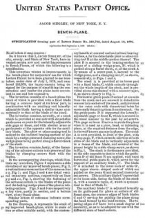
This invention relates to improvements in the benchplane for carpenters’ use for which Letters Patent have been granted to me heretofore, under date of July 1, 1879, and numbered 216,979, the improvements being designed for the purpose of simplifying the construction and render the plane more convenient in use and less expensive.

The invention consists of a bench-plane the stock of which is provided with a fixed blade having a concave taper at its lower part, in combination with an auxiliary and laterally-adjustable blade having a similar taper symmetrically to that of the blade of the stock.

The invention consists, secondly, of a stock; which is provided at one side with detachable guide arms or posts tor the laterally-adjustable side gage or fence, and with shorter arms or guide-posts at the opposite side for the auxiliary blade. The plow or other cutting-tool is secured to the inclined bearing-surface of the stock by a wedge-piece and clamping-screw, the wedge-piece being guided along a flared cheek of the stock.

The invention consists, lastly, of the fastening of the advance cutters into grooves of the blades by clamping-screws flush with the blades.

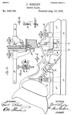
In the accompanying drawings, which illustrate iny invention, Figure 1 represents a side elevation of my improved bench-plane ; Fig. 2, a vertical transverse section of the same on line x x, Fig. 1; and Figs. 3 and 4 are detail vertical transverse sections, respectively on lines y y and z z, Fig. 1, showing the fastening of the advance cutters to the blades of the plane and the locking wedge-piece of the plow or rabbeting-cutters. Figs. 5 and 6 are respectively a top view, partly in section, and a bottom view, of my bench-plane.

Similar letters of reference indicate corresponding parts.

In the drawings, A represents the stock of my improved bench-plane, which is made of iron or other suitable metal, with the customary handle at one end and an inclined bearing-surface, a, for the detachable plow or other cutting-tool B at the middle portion thereof. The plow B is secured to the bearing-surface by means of a sliding wedge-piece, B’, which is guided along a flared cheek, a’, of the stock A by means of a screw-post, b, secured to the wedgepiece, and a clamping-nut, b’, as shown, respectively, in Figs. 1 and 4.

The stock A is provided at its lower part with a fixed blade, C, which extends throughout the whole length of the stock, and is provided at one side thereof with a concave taper, d, as shown clearly in Fig. 2.

Horizontal guideposts D extend at one side from the stock and are screwed in detachable manner into sockets of the stock, and provided at the outer ends with diametrical holes for more easily detaching them from the stock. On the guide-posts D is supported the laterally-adjustable gage or fence E, which is secured in the usual manner to the post by set-screws. This gage orfence E serves to guide the plane when it is used as a plow, bead, or rabbeting plane, at the required distance from the edge, in the well-known manner in planes. The stock A is next provided, in front ofthe plow, with a stop-gage, F, which extends sidewise at both sides of the blade and is vertically adjustable in a recess of the blade, and secured at the proper height by a side clamp-screw, as shown in Fig. 1. The stock is furthermore provided, at the side opposite to that to which the guide-posts D ofthe fence E are applied, with fixed horizontal guide-posts G, which serve for the support of an auxiliary blade, C’ The blade C’ is attached to the lower ends of arms G’, the upper sleeve -shaped ends of which are guided on the posts G and secured thereto by set-screws. This auxiliary blade C’ is provided at its inner side, facing the blade of the stock A, with a concave taper, d’, which is symmetrical to that of blade C.

The auxiliary blade C’ is adjusted laterally on its guide-post for plows or cutters of different sizes, the concave edges of both blades C and C’ serving for guiding the plane along the bead formed by the bead-cutters. The tapering edges d d’ have but a small degree of concavity, so as to be adapted for use with the different sizes of bead-cutters.

The blades C and C’ are arranged between the plow or rabbeting-cutter and the stop-gage F, with advance cutters H, which are shown in Figs. 1 and 3. These advance cutters H are inserted into side grooves of the blades C and C’, which grooves encircle nearly entirely the advance cutters, so that they may be firmly forced by fastening clamp-screws e against the approaching edges ofthe grooves and thereby securely held in position. The cutting-edges of the advance cutters H are thereby in line with the outer surface of the blades C C’, which is essential for the proper action of the advance cutters. The advance cutters serve for all sizes of plows and cutting-irons and dispense with running a gage over the board and prevent the plows from tearing the edges in cross-grained timber.

When the advance cutters are worn out their fastening-screws are loosened and the cutters adjusted by being pushed downward in their guide-grooves and then reclamped by the fastening-screws, the heads of which are preferably flush with the blades. The advance cutters are made of the best steel, sharpened from time to time, and replaced by new cutters when worn out.

By means of the laterally-adjustable auxiliary blade and interchangeable ploivs and cutters the improved bench-plane may be used for grooving, beading, and rabbeting, either as a plow, bead-plane, scratch-bead, match-plane, and dado or rabbeting-plane. When used as a dado the fence and its guide-posts are detached, so as not to interfere with the hand in holding the square. It may be also used by the carpenter for sash-moldings and for other purposes, as it combines a number of useful features in a very compact and durable manner.

Having thus described my invention, I claim as new and desire to secure by Letters Patent —

1. In a bench-plane, the stock with fixed blade G and laterally-adjustable auxiliary blade C’, having concave tapers d’ on their inner sides, and an inclined bearing-surface, a, in combination with the holding device, as shown in Figs. 1 and 4, substantially as set forth.

2. In a bench-plane, the combination of the blades C C’, the side grooves therein, the arms G’, the advance cutters H, the stop-gage F, the guide-post D, and the fence E, substantially as set forth.

3. In a bench-plane, the stock having an inclined bearing-face, a, and a recess with a flaring cheek, a’ a, plow B, a sliding wedge-piece, B’, fixed screw-posts D, and clamping-nut b’, in combination with the fixed and adjustable blades C C’ and advance-cutters H, substantially as set forth.

4. In a bench-plane, the combination of the fixed and adjustable blades C C’, each having a vertical and nearly circular side groove or socket, with advance cutters H and clamp-
screws e, bearing on their inner sides, the advance cutters being, on the outer side, flush with the outer surface of the blades, substantially as set forth.

In testimony that 1 claim the foregoing as my invention I have signed my name, in presence of two witnesses, this 24th day of August, 1880.

JACOB SIEGLEY.

Witnesses:
PAUL GOEPEL,
CARL KARP.