No. 266,519 – Carpenter’s Plow (Frank A. Rappleye) (1882)

[paiddownloads id=”324″]266519


UNITED STATES PATENT OFFICE.

_________________

FRANK A. RAPPLEYE, OF KENDAIA, NEW YORK, ASSIGNOR TO THE STANLEY RULE AND LEVEL COMPANY, OF NEW BRITAIN, CONNECTICUT.

CARPENTER’S PLOW.

_________________

SPECIFICATION forming part of Letters Patent No. 266,519, dated October 24, 1882.
Application filed February 15, 1882. (No model.)

_________________

To all whom it may concern:

Be it known that I, FRANK A. RAPPLEYE, of Kendaia, in the county of Seneca and State of New York, have invented certain new and useful Improvements in Carpenters’ Plows, of which the following is a specification.

My invention relates to improvements in convertible carpenter’s plow and slitting-tool having an attachable and detachable slitting-knife located upon one side of the bottom face of the stock and a fence upon the opposite side of said face; and the objects of my invention are to produce a readily-convertible plow and slitting-tool at a trifling cost over that of an ordinary plow, and to gage and regulate the depth of cut ofthe slitting-knife by means of the bottom face of the stock coming into contact with the top face of the strip severed by the slitting-knife. I attain these objects by the mechanism illustrated in the accompanying drwaings in which —

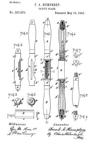
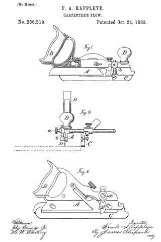
Figure 1 is a side elevation. Fig. 2 is an end view, and Fig. 3 is a side elevation of substantially the same tool in a somewhat different form.

The stock A, handles B B, and adjustable fence C may be the same as in any ordinary plow. It is essential, however, that the fence C shall be adjustable to and from the stock A and capable of being secured in position parallel to the stock, and, as shown in Fig. 2, it should project downward below the bottom edge or face of the stock A.

The patent to Justus A. Traut, of March 4, 1873, shows one good form of a plow-stock and fence; but other plows may be employed, if desired. At one side of the stock A, and near its forward end, is a. vertical socket having transverse set-screws a, within which socket I place the shank b of the slitting-knife D, which knife is a thin blade rounded and sharpened on its forward edge. This knife may be adjusted in its socket or seat, so as to make its point or lower end project any desired distance below the bottom face of the stock A, and when so adjusted it may be firmly held in place by means of the set-screw a. By means of said set-screw and socket the knife is made an attachable and detachable one.

When this plow is to be used for slitting boards or other stock into strips the ordinary plow-bit is removed from the stock A and the slitting-knife adjusted to cut the desired depth by projecting it the desired distance from the bottom face of the stock A. The fence C is also set a distance from the knife D equal to the width of the desired strip. The instrument is then placed with the fence C against one edge of the board to be slit and with the knife over one face of the board, as shown in Fig. 2, said board being indicated therein by broken lines. By bearing down upon the forward end of the plow-stock and forcing it along over the board, substantially as in plowing, the knife can readily be forced into the board until the bottom face of the stock A comes in contact with the face of the board and prevents the slitting-knife from cutting any deeper, thus making the ordinary plow-stock A serve as a depth-gage by its bottom face coming in contact with the upper face of the strip slit off. The stock being close to the knife D, and between said knife and the fence, it can always serve as a depth-gage, even when the piece to be slit is but a hair wider than the distance between the slitting-knife D and the fence C.

In Fig. 3 the slitting-knife D’ is in the form of a flat slotted blade, and the seat which supports said body is in the form of a vertical slot or open socket made in one side of the stock A. A bolt passes from the stock through the slot in the body of the knife, and a set-nut, a’, on said bolt holds the knife in position when once adjusted. The operation is the same as that of the parts shown in Figs. 1 and 2, and hereinbefore described.

It will be noticed that in both forms of knives the fence is upon one side of the stock A and the knife is upon the opposite side.

The additional cost of this improved tool over that of the ordinary plow is much less than the cost of a special slitting-tool, while it is also much more convenient to have the plow convertible into a slitting-tool than it is to use two different tools for plowing and slitting.

I am aware that marking and slitting gages of various styles have been used for slitting boards when the knife or marker was mounted in a stock or frame of its own; also, that a scoring knife or spur has been employed in planes and set between the stock and the fence to prepare the way for the planing-knife, and I hereby disclaim the same.

I claim as my invention —

The convertible plow and slitting-tool, substantially as hereinbefore described, consisting of the plow-stock A, adapted for the attachment and detachment of the ordinary plow-bit, the slitting-knife D, secured to one side of said stock, and the fence C, secured to the opposite side, the bottom face of said stock being between the fence and knife, the latter extending downward from the lower outside corner of the stock, substantially as described, and for the purpose specified.

FRANK A. RAPPLEYE.

Witnesses:
MICHAEL ROAN,
BUEL WILBUR.

No. 264,766 – Miter-Planer (David C. Rogers) (1882)

[paiddownloads id=”323″]264766


UNITED STATES PATENT OFFICE.

_________________

DAVID C. ROGERS, OF GREENFIELD, MASSACHUSETTS.

MITER-PLANER.

_________________

SPECIFICATION forming part of Letters Patent No. 264,766, dated September 19, 1882.
Application filed June 27, 1882. (No model.)

_________________

To all whom it may concern:

Be it known that I, DAVID C. ROGERS, a citizen of the United States, residing at Greenfield, in the county of Franklin and Commonwealth of Massachusetts, have invented a new and useful Improvement in Miter-Planers, of which the following is a true and full specification.

The accompanying drawings show the invention, and form part of this specification, in which —

Figure 1 is a plan showing the several features of my invention. Fig. 2 is a vertical central section of the same. Fig. 3 is a detail showing the rest G.

Similar reference-letters indicate like parts in all of the figures.

A represents the fixed bed-plate, semicircular in term, having at its rear the frame B, on which the plane runs, having a groove on its under side matching on a tongue to keep it true and steady. This bed-plate has on its outer upper edge notches placed at regular and fixed intervals, into which drops a catch from the upper bed-plate, to hold it securely at any angle desired.

C is the upper movable bed-plate, in quadrant form, having at right angles sides D D, which act as guides for the material to be planed, and revolving on a pivot at the rear end or apex touching the plane, passing through the lower bed-plate. These sides or guides are so accurately arranged with reference to the plane that when the movable bed-plate C is set with its center-line at a right angle to the plane a stick placed on either side will be planed to a perfect “miter.” The revolving movement of this bed-plate C is controlled by a screw and clamp, E, fixed in the upper bed-plate, and passing through a segmentally-shaped slot in the lower bed-plate, in which is a nut which clamps the upper bed-plate firmly in position when it is desired to fix it permanently at any given angle to the plane. This is commonly such as to finish the work at an angle of forty-five degrees, or a true miter. The movable bed-plate C is also provided at its outer edge with a small lever, F, controlled by a spring, and having on its under side a catch which is pressed down into the notches on the lower bed-plate, so arranged as to hold the stick to be planed at any given angle to the plane.

About midway in length of the sides D, and let in so as to be flush with the face of each side, is a rest, G, at the bottom of which is a segmental arm running back in ways on the movable bed-plate C, having through its length a slot through which into the said bed-plate passes a screw controlling its movement back and forth. The special purpose of this rest is to enable one to finish the ends of curved work with exactness.

In preparing pieces for circular or oval frames, for pulleys, emery-wheels, circular patterns, and all such work, it is necessary to plane the ends of the various segments composing the same at different angles, and when a curved stick is to be planed, the end must be closely pressed against the side or guide which supports it; but in doing this of course the other end of the curve is thrown out and away from the guide, as the stick can only touch the guide at the extreme end which is to be planed. Consequently, except at that point, the stick has no support but the unreliable action of the hand. To provide for this, the movable rest is run out till it touches the work on the outer curve, and then being secured by turning down the screw in the slotted segmentary arm forms a complete rest and support for the work to be planed.

This device supplies a want hitherto needed.

What I claim in a miter-plane is —

1. In a machine for planing miters, the quadrantal pivoted bed-plate, provided with segmental guardways fixed thereon, in combination with rests G, provided with segmental clamping-arms adapted to hold the material to be mitered in position for the planer, as and for the purpose set forth.

2. The combination, with the tired bed-plate A and frame B, of the pivoted bed-plate C, provided with adjustable rests G, substantially as and for the purpose set forth.

DAVID C. ROGERS.

Witnesses:
JAMES S. GRINNELL,
WM. H. ALLEN.

No. 258,988 – Bench-Plane (William S. Case) (1882)

[paiddownloads id=”322″]258988


UNITED STATES PATENT OFFICE.

_________________

WILLIAM S. CASE, OF NEW BRITAIN, CONNECTICUT.

BENCH-PLANE.

_________________

SPECIFICATION forming part of Letters Patent No. 258,988, dated June 6, 1882.
Application filed March 17, 1882. (No model.)

_________________

To all whom it may concern:

Be it known that I, WILLIAM S. CASE, of New Britain, in the county of Hartford and State of Connecticut, have invented certain new and useful Improvements in Bench-Planes; and I do hereby declare that the following is a full, clear, and exact description thereof, whereby a person skilled in the art can make and use the same, reference being had to the accompanying drawings, and to the letters of reference marked thereon.

Like letters in the figures indicate the same parts.

My improvement relates to a new mechanism for adjusting the iron of a bench-plane to a greater or less depth of cut; and its object is to provide a simpler and cheaper device than has heretofore been in use for this purpose, and at the same time one which can be readily and easily operated.

In the accompanying drawings illustrating my invention, Figure 1 is a longitudinal vertical section through the middle of the plane. Fig. 2 is a top view with the plane-iron removed so as to show the working parts. Fig. 3 is a front view of the cam which operates the lever which moves the plane-iron up or down.

A is the stock of an ordinary plane furnished with a handle and knob in the customary manner.

B is the bit, and C the cap, of the plane-iron. The bit and cap are held together by means of the screw D, which screws into the cap and moves in a slot in the bit to adjust the position of the two parts in the customary manner.

E is a metallic plate attached to the stock A, for the purpose of holding the working parts of the plane.

The plane-iron is held in place by the wedge F, which passes under the bar G, and is provided with a set-screw, H, which clamps the plane-iron against the bearings E’ and the back of the bottom of the slot in the stock.

J is a forked lever turning upon a pin, K, passing through lugs upon the plate E. The forward end of this lever is single. It passes through the slot in the bit B and enters a hole or notch in the cap C. The rear end of this lever is forked, and embraces a swinging cam, L, upon the rocking lever M.

M is a lever swinging laterally upon the pin N, by which it is attached to the plate E. Upon its front side is the cam L for operating the lever J, one of the forks of the said lever resting on the top and the other on the bottom of the cam. The movement of the lever M to the right or left raises or lowers the plane-iron, so that its edge will project more or less through the throat of the plane to adjust it to different degrees of depth in the cut. When the rear end of the lever M is pushed to the right it depresses the rear of the lever J and raises its forward end. This lifts the cap and carries with it the bit. To lower the bit the rear of the lever M is pushed to the left, which reverses the movements above described.

What I claim as my invention is —

In a bench-plane, the combination of the laterally-swinging lever M, provided with the cam L and the vertically-swinging forked Iever J, pivoted to the plate or frame E, with the said plate and the plane-iron, substantially as described.

WILLIAM S. CASE.

Witnesses:
EDWIN F. DIMOCK,
THEO. G. ELLIS.

No. 258,971 – Reed-Plane (Frederick V. Yeager) (1882)

[paiddownloads id=”321″]258971


UNITED STATES PATENT OFFICE.

_________________

FREDERICK V. YEAGER, OF PHILADELPHIA, PENNSYLVANIA.

REED-PLANE.

_________________

SPECIFICATION forming part of Letters Patent No. 258,971, dated June 6, 1882.
Application filed August 26, 1881. (No model.)

_________________

To all whom it may concern:

Be it known that I, FREDERICK V. YEAGER, a citizen of the United States, and a resident of the city and county of Philadelphia, in the State of Pennsylvania, have invented certain new and useful Improvements in Reed-Planes, of which the following is a specification, reference being had to the accompanying drawings, wherein —

Figure 1 is a side elevation of my improved reed-plane. Fig. 2 is an elevation of the reverse side of the same. Figs. 3 and 4 are tranverse vertical sections, and Fig. 5 is an inverted plan of the same.

My invention has for its object to provide a plane for working reeds across the grain of wood. Heretofore such result has been obtained by means of a saw and chisel, and to produce a cluster of reeds by such means required great care and consumed much time and labor, thereby making the operation one of extreme tediousness and expense. With my improved plane, however, reeds can be worked across the grain of wood with ease and rapidity.

My invention consists in the novel construction and arrangement of the plane, as hereinafter more fully described.

Referring to the accompanying drawings, A represents the stock of the plane, B the hit thereof, and C the wedge for securing said bit in an opening in said stock. The bit B is formed with a projecting convex cutter, b, being outside ground, as shown at b’.

D D’ are cutters, passing through an opening, a, in the forward part of the plane, and are held therein by means of a wedge, E. Said cutters are placed a distance apart equal to the width of the reeds designed to be worked, and have their lower or cutting edges serrated, as shown at d.

F represents the sole of the plane, made in three sections, f f 1 f2. The sections f f2 are stationary. The section f1 is formed with a slot, f4, through which passes a screw, f5, into the stock A, as plainly shown in Fig. 4. By loosening said screw the section f1 may be adjusted to and from the cutting-edge of the bit B to regulate the thickness of the chip or shaving designed to be cut, so as to insure smoothness of working.

G is a gage, secured to stock A by pivoted links g g; and H is a thumb-screw passing through a curved or other suitable slot, g’, in the gage, and screws into the stock A, the effect whereof is that when said gage is raised or lowered, and the thumb-screw H turned, its head h will impinge against said gage, and will thereby retain the latter in its adjusted positions.

The operation is obvious, and as follows: In forming the first reed of a cluster the gage G is raised, as shown in Figs. 2 and 3, and the plane is moved to and fro across the grain of the wood. During each such forward movement the cutters D D’ scribe or cut two parallel lines in advance of the bit B, so that the cutting-edge of the latter merely removes the chip or shaving between the lines so formed by the cutters D D’. Consequently a smooth or unbroken reed can be formed across the grain of wood by such plane. After the first reed is worked the gage G is lowered by flrst loosening the thumb-screw H, which allows the gage to fall, whereupon it is held in such position by turning said screw until its head binds against the gage. The latter is then placed in the outside crevice of said first-formed reed, so that the latter forms a guide to assist in the working of the second reed. By such means each succeeding reed is formed parallel to its immediate predecessor, such operation being plainly illustrated in Fig. 4.

What I claim as my invention is —

1. In a plane for working reeds across the grain of wood, the combination of advance cutters D D’, having serrated cutting-edges d, plane-bit B, having convex cutter b, outside ground or bevel, b’, sole F, having adjustable section f1, and gage G, secured to the body of the plane by links g g, and provided with a thumb-screw, H, substantially as shown and described.

2. In a plane for working reeds across the grain of wood, the combination of main bit B, having convex cutter b, outside ground or bevel, b’, advance cutters D D’, provided with serrated cutting-edges d d, and adjustable sole-section f1, substantially as shown and described.

In testimony that I claim the foregoing I have hereunto set my hand this 23d day of August, 1881.

FREDK. V. YEAGER.

Witnesses:
CHAS. W. HOPPLE,
GEORGE H. VANDEGRIFT.

No. 257,981 – Bench-Plane (Solon R. Rust) (1882)

[paiddownloads id=”320″]257981


UNITED STATES PATENT OFFICE.

_________________

SOLON R. RUST, OF PINE MEADOW, CONNECTICUT.

BENCH-PLANE.

_________________

SPECIFICATION forming part of Letters Patent No. 257,981, dated May 16, 1882.
Application filed September 8, 1880. (No model.)

_________________

To all whom it may concern:

Be it known that I, SOLON R. RUST, of Pine Meadow, in the county of Litchfield and State of Connecticut, have invented a certain new and useful Improvement in Bench-Planes, whereof the following is a description, reference being had to the accornpanying drawings, where —

Figure 1 is a side view of a plane embodying my said improvement — an “iron plane” — with a portion of the side of the stock represented as broken away. Fig. 2 is a. view of the same plane from above, with the plane-iron, cap-iron, and fastening-lever removed. Fig. 3 is a view in central vertical lengthwise section of a modification.

The improvement is one in that kind or class of planes wherein the bed on which the “cutting-iron” rests, the cutting-iron, (with the “cap-iron,” if there be one,) and the clamping or fastening-in lever all move together in the ordinary longitudinal adjustment of the cutting-iron; and the improvement consists in such an organization and combination of parts that this bed, cutting-iron, and fastening-lever may be put into and taken out of the plane-stock when assembled together as a whole,instead of having to put them into and take them out of the stock separately, as has heretofore been the case.

The letter a denotes the stock of an iron plane as a whole, consisting, in general terms, of the bottom plate and two side plates rising therefrom. The inner sides of these side plates bear the ways b, and in them rests and slides the bed c, bearing underneath the lug d, through which a shaft, e, runs, it bearing at the rear end a head or button whereby to rotate it, and it being threaded at the other end and there taking into a corresponding female thread made in a portion of the stock a. Where this shaft traverses the lug d it has an annular groove made in its periphery, into which the pin f meshes. By rotating this threaded shaft e the bed c is moved up and down in its ways.

The letter g denotes a fulcrum-bar carried by and upon the bed c. The letter h denotes the clamping-lever, which finds a fulcrum on this bar g. One end of this lever bears on the cap-iron i, (if there be one, otherwise directly on the plane-iron j,) and the upper end of this lever carries a set-screw, k, which bears on the upper end of the cap-iron (if there be one) with any desired pressure, and thus holds the cutting-iron, cap-iron, and itself firmly to the bed c, so that the plane-iron can be adjusted by adjusting the bed c by means of the screw-shaft e.

In Fig. 3 I show a modification wherein the fulcrum or fulcrum-bar is attached to the clamping-lever, and, running down through the “irons,” takes hold of the bed, the irons being rnortised for the passage of the fulcrum-bar, and the bed having a mortise which permits the enlarged head or end of this bar to pass through it at one point, but catches and holds it by its neck at another point.

It will be seen from this description that the iron, the bed on which the iron rests, and the clamping-lever may be put into and taken out of the stock as a whole, and that they all move together in the ordinary longitudinal adjustment of the iron.

I am aware that the prior art contains plane-irons made adjustable by a screw. See, for instance, the patent to H A. Gateley, No.146,588, dated January 20, 1874, which has a double iron, but no movable bed — a construction that necessitates (as my construction does not) a loosening of the clamping-lever before the adjusting-screw can be operated.

I am also aware that the prior art contains a combination of movable bed, plane-iron, adjustable screw or the like, and clamping-lever, where the clamping-lever does not take its fulcrum on the movable bed. See, for instance, patent to G. M. Thompson, No. 153,399, dated July 21, 1874; but that construction does not (as my construction does) admit of the placement and displacement of the bed, iron, and clamping-lever as an assembled whole in and out of the plane-stock.

I am also aware that the prior art contains the combination of movable bed, plane-iron, and clamping-lever taking its fulcrum on the movable bed, when the movable bed is not hung in ways in the side plates of the stock, but is hung on a headed screw running through a longitudinal slot made in the movable bed into the solid stock, as shown in O.R. Chaplin’s Patent No. 126,519, dated May 7, 1872 — another construction that does not admit (as my construction does) of the placement and displacement of the movable bed, iron, and clamping-lever as an assembled whole.

One prominent advantage cf having the movable bed, iron, and clamping-lever admit of placement and displacement as an assembled whole is this: When a plane is in constant use it must be taken out of the stock a number of times each day to be ground and sharpened. When the iron goes back into the stock it must be adjusted relatively to the movable bed each time, (independent of the adjustment by the adjusting-screw,) and this adjustment can in my construction be made while the movable bed and iron are out of the stock — a thing which cannot be done in any structure of said prior art-and may be done much more easily than when the movable bed, iron, and clamping-lever are in the stock.

I claim as my improvement —

The stock a, provided with ways b in the side plates thereof, the bed c, hung in such ways, the cutting-iron j, and the clamping-lever k, taking its fulcrum on bed c, all combined substantially as described, for the purpose set forth.

SOLON R. RUST.

Witnesses:
ARTHUR E. RUST,
NATHAN MORSE.

No. 257,870 – Cavity-Plane (Frank A. Humphrey) (1882)

[paiddownloads id=”319″]257870


UNITED STATES PATENT OFFICE.

_________________

FRANK A. HUMPHREY, OF WORCESTER, MASSACHUSETTS.

CAVITY-PLANE.

_________________

SPECIFICATION forming part of Letters Patent No. 257,870, dated May 16, 1882.
Application filed November 28, 1881. (No model.)

_________________

To all whom it may concern:

Be it known that I, FRANK A. HUMPHREY, of Worcester, in the county of Worcester and State of Massachusetts, have invented certain new and useful Improvements in Cavity-Planes for Pattern-Makers, Wood-Workers, and Others; and I declare the following to be a description of my said invention sufficiently full, clear, and exact to enable others skilled in the art to which it appertains to make and use the same, reference being had to the accompanying drawings, which form a part of this specification.

The object of my present invention is to provide a practical and efficient tool which can be conveniently employed for dressing out small holes and cavities, and for smoothing narrow surfaces located between or near flanges or angles; also, for working out small curves, and for general whittling and planing in positions inaccessible or inconvenient for working with the ordinary tools.

To this end my invention consists in the improved tool illustrated and described, and in the peculiar constructive features and combinations appertaining thereto, and hereinafter specifically claimed.

In the drawings, Figure 1 is a top view of my cavity-plane with full handles in position. Fig. 2 is a bottom view of the same with one of the handles disconnected. Fig. 3 is a front view with both handles shortened or interchanged. Fig. 4 is a longitudinal sectional view at line x x, Fig. 1. Fig. 5 is a transverse sectional view at line y y, Fig. 1. Fig. 6 is an end view. Fig. 7 shows detail of one of the chuck-pieces for locking the blade in position. Fig. 8 shows a side view of the handle separate from the other parts. Fig. 9 is a side view of the convertible handle-tip, and Fig. 10 shows the form of the blade or cutter.

In the construction, A denotes the body or frame, having a rounded back bar, a, and a forward guard-flange, a’, connecting the cylindrical ends or neck-bosses A2, in the manner illustrated.

B indicates the blade or cutter, formed as a straight rectangular plate, sharpened along one edge, b, and without holes or openings of any kind. Said blade is seated and supported on the inner surface of the back bar, a, (which is properly fitted for its reception,) with its sharpened edge b protruding throngh the throat-opening t at the rear of the guard-flange a’, the blade being set at the proper angle and at such distance from the guard a’ as to give a free cutting action when in use. The shavings pass up through the central opening, and are directed backward by the upper edge of the guard a’, which is made to incline inward for that purpose.

C C indicate chuck-pieces for retaining the blade B in position. Said chuck-pieces fit into the recesses of the frame ends, and are provided with bevels c’ at their rear edges, which are forced against the ends of the blade and clamp it securely in position. The blade B can be held securely in position by either one or both of the chuck-pieces C.

D indicates the handles, which are fitted with screw-threaded connecting-studs D’, for screwing into the central openings of the frame ends A2, and against the chuck-pieces C, for serving the double purpose of attachments for the handles and clamp-screws for the blade B.

E indicates short handles or tip-pieces, which are employed as clamp-screws for retaining the blade when it is desired to adapt the tool for use in a narrow space, as in Fig. 3. Said tips or clamp-screws are provided with ends E’ of the same size and pitch as the connecting-studs D’ of the handles, so as to be readily interchangeable therewith. In the present instance the clamp-screws are made to serve as tips for the wood handles D, but, if desired, could be independent parts, the handles being made complete without them. I prefer, however, to construct them as convertible tips in preference to independent set-screws, and I arrange them in combination with the handles as follows:

The tang or shank D2 of the screw-studs D’ is made to extend completely through the wood of the handle, (the ferrule D3 being formed integral therewith, ) and a screw-thread formed on its outer end, d. The end of the wood handle is recessed, and the piece E, which is furnished with a central screw-threaded opening, screws onto said end d of the tang and forms the finishing-tip of the handle when not required for use, as in Fig. 3. The tips E are provided with recesses or nicks e, and small ribs or projections f may be made on the ends of the connecting-studs D’, (see Figs. 4 and 8,) which fit said nicks, so that the handle can be used as a screw-driver for starting or screwing up said tip-pieces on the handle or frame ends.

Lugs i maybe formed under the fcrrnles D3, to prevent the wood handle from turning on the tang D2. The shape of the handles can be modified to adapt the tool for convenient application or use on different classes of work.

The tool can be used with two handles, as in Fig. 1, or with a single handle, (either right or left,) as in Fig. 2, or with only the short body and clamp-screws E, (one or both,) as in Fig.
3, thus permitting of its convenient use in narrow spaces between flanges and ribs. It can also be used for planing out small cavities and holes, and can be successfully used in any hole of sufficient size to admit of its entrance, (see dotted line, Fig. 6,) or from three-fourths of an inch diameter upward, while it can be used for right or left hand whittling on straight or convex surfaces and in small corners and angles. The blade can be quickly and conveniently adjusted to cut thin or rank shavings, as required, and said blade can be worn away to a very narrow strip before it requires renewal of the blade. The tool is of great utility and convenience in pattern-making, cabinet-work, and other branches of wood-working, wherein small cavities and various formed recesses require to be worked and smoothed out.

What I claim as of my invention, and desire to secure by Letters Patent, is —

1. The body or frame formed with cylindrical ends or neck-bosses, connected by the externally-rounded back bar and inwardly-inclined guard-flange, and the straight cutting-blade seated on said back bar, with its sharpened edge protruding through the throat-opening at the rear of said guard-flange, the parts being combined and located in relation to each other and the exterior curvature substantially as shown and described.

2. The combination of the body or frame having the back bar and front guard, the straight blade supported on said back bar, and the chuck-pieces fitted into said frame and pressed against the ends of said blade in direction of its length by a screw or clamping device axially arranged within the ends of the frame, for retaining it in position, substantially as set forth.

3. The combination, substantially as hereinbefore described, of the frame having hollow screw-threaded ends A2, connected to each other by the backbar, a,and guard-flange a’, as shown, the straight cutting- blade B, seated on said back bar, the chuck-pieces C, fitted in recesses of the frame ends and resting with a beveled surface against the ends of said blade, and the detachable handles D, having studs or threaded ends for screwing into said frame ends and against said chuck-pieces, for the purposes set forth.

4. The combination with the detachable handles D and blade supporting frame A, of the convertible tip-pieces E, adapted for use as set-screws for the chuck-pieces when the handles are detached, or as end nuts on said handles, substantially as hereinbefore described.

5. The combination, with the body or frame A, of the handles D, having the screw-threaded end studs, D’, with projection f, ferrule D3, and tang D2, screw-threaded at its outer end d, and the convertible tip-pieces E, with nicks e, as shown and described.

Witness my hand this lst day of June, A. D. 1881.

FRANK A. HUMPHREY.

Witnesses:
CHAS. H. BURLEIGH,
GEO. M. RICE, 2d.

No. 254,542 – Variable Bench-Plane (Amos Fales) (1882)

[paiddownloads id=”318″]254542


UNITED STATES PATENT OFFICE.

_________________

AMOS FALES, OF DENVER, COLORADO.

VARIABLE BENCH-PLANE.

_________________

SPECIFICATION forming part of Letters Patent No. 254,542, dated March 7, 1882.
Application filed December 12, 1881. (No model.)

_________________

To all whom it may concern:

Be it known that I, AMOS FALES, of Denver, in the county of Arapahoe and State of Colorado, have invented an Improved Kit-Plane, or combination instrument for planing, tonguing and grooving, rabbeting, plowing, and forming beads and moldings of various forms and styles; and I do hereby declare that the following is a full and exact description thereof, reference being had to the accompanying drawings, making part of this specification —

Figure 1 being a view of the near or working side of the kit-plane; Fig. 2, a view of the opposite side of the same; Fig. 3, a top view thereof; Fig. 4, a cross-section thereof in a plane indicated by the line x x, Fig. 1; Fig. 5, a cross-section in a plane indicated by the line y y, Fig. 1; Figs. 6, 7, 8, and 9, cross-sections of the stock, showing in place different forms of face-plates or molds attached to the stock; Fig. 10, a view of one of the bits or cutters used with the molds, representing two forms; Fig. 11, a view in perspective, showing an auxiliary stock or attachment, connected with the main stock by gage-bars, for various purposes; Figs. 12 and 13, respectively, opposite side views of the attachment or auxiliary stock; Figs. 14: and 15, partial sections, showing parts in detail.

Like letters designate corresponding parts in all of the figures.

My invention consists in a kit plane of simple but peculiar construction, by which are combined a stock adapted to receive any required kind of bit or cutter for producing various shapes of moldings and other outlines in wood-work, and attachable and detachable forms or molds of various shapes, to correspond with those of the cutters, for performing a great variety of work which ordinarily require many different planes or instruments.

The plane-stock A is of very simple and light construction. It may be made of metal — say of cast-iron — finished suitably, and accurate in shape, and it may have a wooden handle, B, attached to the stock by screws a a. This of course is at the rear end of the stock, and it has or may preferably have a wooden knob, C, near the front end, on top, for holding and guiding the instrument with the left hand.

On the working side of the stock, near the middle thereof, an oblique projecting ledge or bracket, D, is cast on or attached to the stock, on which ledge the various cutters used with the instrument rest when employed. Each cutter E is supported by this ledge, guided only at one edge, next to the stock, the opposite edge being free, so that various widths of cutters may be used with the stock.

Instead of a wedge working downward to fasten each cutter in the stock, I employ a wedge, G, working horizontally and entering a deep wedge-shaped notch or recess, b, in the stock, which is enlarged on the opposite side, as shown in Fig. 3, to compensate for the weakening produced by the said notch, and thereby to give uniform strength throughout the length of the stock. A horizontal screw-bolt, c, passes through the wedge G, or is otherwise made fast to it, and thence extends through and projects a little beyond the stock, on the opposite side thereof. On this screw-threaded end of the bolt a hand-nut, d, screws against the side of the stock, and thereby draws the wedge into its notch or socket, and tightens and holds the cutter fast on its ledge. Thus not only is each cutter always securely held and easily adjusted, but great facility is afforded for changing cutters.

The upper part, e, of the stock is made thick enough to give necessary strength and to suitably attach other parts directly connected therewith. The lower part, f is a thin blade or flange to which to attach the planing-molds, now to be described.

In connection with the various forms of cutters to be used in the stock, two face-plates or molds, H I, are used, one situated forward of and the other back of the cutter, substantially as shown in Fig. 1. Each pair of molds for each different form of cutter is of like form in cross-section to fit the form produced by the cutter between them and guide the plane and hold it in the proper course. Each one has a vertical flange, g, fitting against one side of the flange f of the plane-stock, and by this flange it is united to the stock with a screw, h, passing through both flanges, and a hand-nut, i, turning thereon, one screw and nut serving for each mold. For convenience in attaching and detaching the molds, the opening in the flange g to receive the screw is a notch, as shown in Fig. 1, so that the attachment and detachment can be effected without removing the nut simply by loosening and then retightening the same. To hold the molds thus attached in accurate position, there is a shoulder, j, from each under the lower edge of the stock-flange f as shown in the several cross-sections. The body or form it of each mold projects laterally from the flange in a general horizontal direction, but varied according to its form, as seen also in the several cross-sections showing different forms of molds.

Several of the more common forms of molds which may be used with this kit- plane are shown in the drawings. Thus Fig. 4 has the dado form or mold; Fig. 5, a fillister form, with adjustable gage l thereon; Fig. 6, a hollow form, for producing a convex molding; Fig. 7, a round or convex form, for producing a concave molding; Fig. 8, a bead-mold, and Fig. 9 a “snipe’s-bill” mold. All these and other molds to be used have corresponding forms of cutters at the cutting-edge thereof. Thus Fig. 10 shows a cutter having a form or cutting-edge at each end, that at one end corresponding and used with the hollow mold shown in Fig. 6, while that at the other end has a form corresponding and used with the convex mold shown in Fig. 7.

Ordinarily thus two forms of cutter may be united in one, if economy of expense and room occupied by the whole instrument is desired. These molds or face-plates may be made thin and light, since very little strain comes upon them, and they are very well and securely held on the stock. They are so simple in construction and easy of application that when any one wants any particular style of molding, bead, or other work for which he has no mold or cutter he can easily shape molds — say out of wood — a little thicker than the metallic forms, as shown, and make a cutter to correspond. In this manner, at little expense, one can supply himself with almost anything of the kind which he may desire.

Some of the cutters and molds used with this instrument require a gage-stop to limit the depth to which they shall go. Thus for the dado and fillister shown in Figs. 4 and 5 such a stop needs to be used, and I have shown in Fig. 5, as well as in Fig. 1, my construction and arrangement for this purpose. I employ a transverse bar, J, which extends through a mortise or notch, m, in the stock, and this, for convenience, is held in position by the knob C, which, screwing down on the stock, serves as a nut to hold the bar, which can thereby be adjusted longitudinally to any desired position. This bar carries the gage-stop K, the stem n of which passes up through a hole in the bar, and is held at any height to which it may be adjusted by a set-screw, o.

For some special purposes, where two cutters are required running parallel with each other, I employ a light auxiliary stock, L, as shown in Figs. 11, 12, and 13, the former figure showing the stock and the means of connecting it with the main stock, and the latter two figures showing opposite side views of the cutter-holder separate. This stock is of similar construction to the main stock, but it is not so heavy, and does not require a handle nor a holding-knob. It has a similar construction for holding and securing its cutters and similar molds, corresponding in form with the respective cutters; but the cutters and molds are placed on the other side of the stock, as compared with the main stock, so that the two stocks and their adjuncts are right and left to one another, the cutters and molds of both being inward and facing one another, as shown.

The two stocks are connected together by two bars, J M, the former fitting the mortise m in the main stock and taking the place of the gage-bar J, above described, being held in the main stock by the knob C; but it may be required to be longer than the said gage-bar for its purposes. It extends through a corresponding mortise or aperture in the auxiliary stock, and is held fast therein by a set-screw, p. The other bar, M, parallel with the former bar, passes through holes or mortises in the two stocks, and is held therein by set-screws q, that in the main stock not being represented in the drawings. The bar M may be round. By this construction the auxiliary stock may be adjusted to any desired distance from the main stock.

On the bar J a gage-stop, K, is used, similar to that on the bar J; but it is represented in Fig. 11 as constructed to slide on the bar. Its construction is shown in Fig. 14. It is secured in any position by a set-screw, o.

With a proper cutter in the holder O, together with a suitable cutter in the main stock, the two sides of a tongue for tonguing and grooving are formed. By adjusting the auxiliary stock farther from or nearer to the main stock a thicker or thinner tongue is made.

By making the cutter-holder O detachable from the auxiliary stock and attaching a dado or fillister form, P, (shown separate in Fig. 15,) to the back part of the auxiliary stock, a back fillister is produced to go with the main instrument. The cutter-holder O and fillister form P are attached to the auxiliary stock by bolts and thumb-screws s s, Fig. 11.

The above are instances which indicate also other and varied uses of which the entire instrument is capable.

This whole instrument, with all the parts herein described, by taking apart, can be packed in a box less than a foot in length, six inches in breadth, and four inches in depth, interior dimensions, and thus a complete set of such instruments becomes very portable and compact and of comparatively small cost. Instruments of the ordinary construction having all the various capabilities and uses herein specified, if made separately, would occupy many times as much space and be many times more expensive.

What I claim as my invention, and desire to secure by Letters Patent, is —

1. A kit-plane constructed with a stock, A, as described, changeable cutter E, and separate changeable front and back form-plates, H I, the said form-plates being independently attached to the stock, substantially as and for the purpose herein specified.

2. The stock A, constructed with a ledge or bracket, D, projecting from one side thereof, and of sufficient width to support all the different widths of cutters used, with the laterally-acting wedge G to clamp the cutters on the ledge, and with the vertical flange f, to one side of which the front and back form-plates are attached, substantially as and for the purpose herein specified.

3. The separate form-plates or molds H I, each constructed with the horizontally-extended body or form k, the vertical flange g, for attaching to the stock-flange f and the ledge or shoulder j, for holding them accurately in line under the flange f, substantially as and for the purpose herein specified.

4. The combination, with the stock A, of the cross-bar J and gage-stop K, the former being horizontally adjustable in the stock and the latter mounted and vertically adjustable in the cross-bar, substantially as and for the purpose herein specified.

5. The auxiliary stock L and its removable cutter-holder O and mold-forms P, in combination with the main instrument, substantially as and for the purpose herein specified.

The foregoing specification signed by me this 22d day of August, 1881.

AMOS FALES.

Witnesses:
A. C. LEWIS,
J. P. LESHEN.