No. 289,459 – Spokeshave (Gary B. Smith) (1883)
UNITED STATES PATENT OFFICE.
_________________
GARY B. SMITH, OF DENVER, COLORADO, ASSIGNOR TO ROBERT E. PERRY, OF SAME PLACE.
SPOKESHAVE.
_________________
SPECIFICATION forming part of Letters Patent No. 289,459, dated December 4, 1883.
Application filed August 15, 18803. (No model.)
_________________
To all whom it may concern:
Be it known that I, GARY B. SMITH, a citizen of the United States of America, residing at Denver, in the State of Colorado, have invented certain new and useful Improvements in Spokeshaves; and I do hereby declare the following to be a full, clear, and exact description of the invention, such as will enable others skilled in the art to which it appertains to make and use the same.
This invention relates to that class of spoke-shaves having adjustable bevel gage-stops, which serve to gage the spokeshave for chamfering; and the objects of this improvement are to fit the parts composing the bevel gage-stop without the aid of screws and to improve the construction of this class of spokeshaves, whereby the material (wood) can be accurately cut at all the desired angles.
With these and other objects in view my invention consists in a bevel gage-stop for a spokeshave, composed, essentially, of three parts united for angular inclinations. My invention further consists in the novel construction and combination of parts, as will be hereinafter more fully set forth.
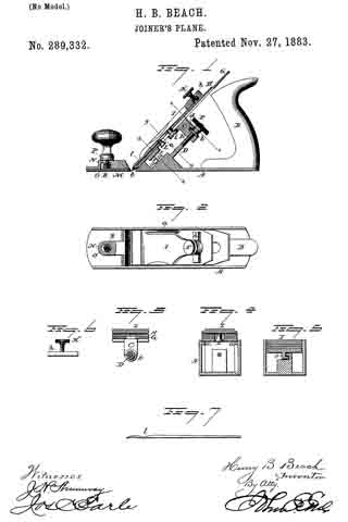
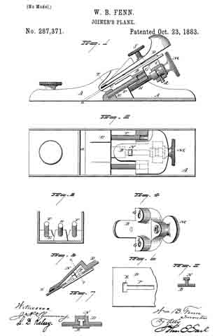
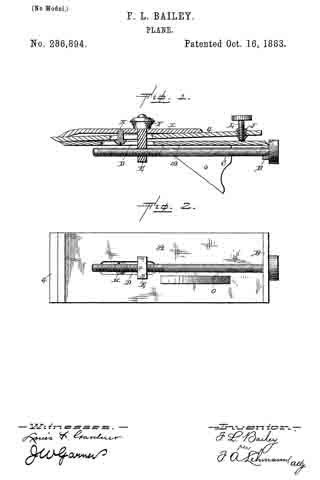
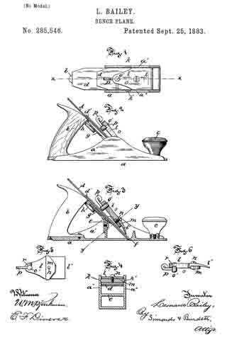
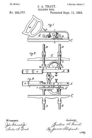
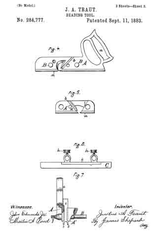
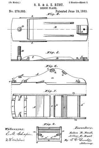
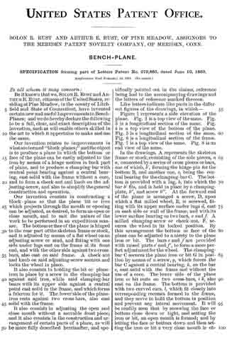
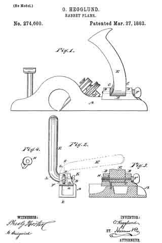
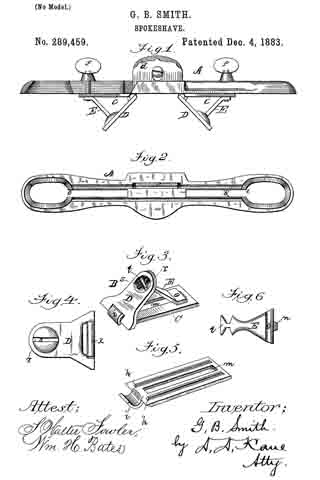
In the annexed drawings, Figure 1 is a side view, partially in section, of my improved spokeshave. Fig. 2 is a plan view of the under side of the stock. Fig. 3 is a perspective view of the bevel gage-stop. Fig. 4 is a plan view of the angle-plate. Fig. 5 is a perspective view of the horizontal plate, and Fig. 6 is a plan view of the bar that connects the angle and horizontal plates.
In the manufacture of the spokeshave the stock A is preferably made of malleable iron, and is formed with two parallel grooves, b, extending in the direction of the length of the stock. The continuity of one of these grooves is broken about midway of its length by the throat-slot c, for the reception and passage of the plane-bit d and set-iron with its screw, as seen in Figs. 1 and 2 of the drawings. This stock is also formed at the opposite ends with the longitudinal slots e e, for the reception. and adjustment of the thumb-screws f, connected to the bevel gage-stops, hereinafter described; also, the continuation of the slots into and the enlargement of the same in the ends of the stock will permit of the ready removal of the stops. This is accomplished by loosening the set-screws f a little, then adjusting the stops until the set-screws drop through the enlarged openings. The bevel gage-stop B, as seen in Figs. 1 and 3, is essentially composed of the horizontal plate C, the angular face-plate D, and the diagonal connecting-bar E. The horizontal plate B is formed with two longitudinal tongues, h, arranged to fit and work in the grooves b of the stock. Its inner end is formed with an overlap-joint, i, for attachment to the transverse bar K of the angular face-plate D, and the plate is also formed with a longitudinal slot, in, for the reception of a rectangular or other shaped boss, n, on the upper end of the connecting-bar E. The opposite or lower end of the angular face-plate D is formed with a concave or depression, r, and a slot, s, in the concave part to receive the reduced portion and cross-bart of the connecting-bar, as shown in Figs. 1 and 2 of the drawings. The connecting-bar, in connection with the slot in the horizontal plate and thumb-screw, is for adjusting the inclination of the angular face-plate. By this construction of the members composing the bevel gagestop the parts are readily coupled together without the aid of auxiliary fastening means, and no portion of the connecting means projects beyond the face of the angular plate. The bevel gage-stops are attached to opposite sides of the plane-bit, as seen in Fig. 1 of the drawings, by means of the thumb-screws passed through the slots of the stock and connected to the rear ends of the connecting-bars of the gage-stops. To adjust the gage-stops to or from the plane-bit, or to secure a different angle to the face-plates D, the thumb-screws are loosened and the gage-stops are adjusted as desired, or the inclination of the face-plates set at the required angle, when the thumb-screws are again made secure.
This spokeshave is used substantially in the manner as those of the same class. I wish to reserve the right to vary the construc-
tion and arrangement of parts without departing from the spirt of the invention.
What I claim is —
1. In a spokeshave, the bevel gage-stop composed, essentially, of the slotted horizontal plate, the angular face-plate hinged to the inner end of the horizontal plate, and the adjustable connecting-bar loosely connected to the lower end of the faceplate with a set-screw, substantially as set forth.
2. In a spokeshave, the combination of the horizontal-plate formed at one end with an overlap joint, and the angular face-plate formed with the transverse bar for connection with the overlap-joint of the horizontal plate, whereby a hinge-connection is formed for the relative adjustment of the face-plate, substantially as described.
3. The bevel gage stop for a spokeshave, consisting of the slotted horizontal plate formed with the parallel ribs and overlap-joint, the angular face-plate formed with the transverse bar and the concave or depression, and the connecting-bar formed with the boss and the cross-bar, said members being organized substantially as described.
4. The improved spokeshave consisting, essentially, of the stock; formed with longitndinal slots enlarged at the outer ends, slotted plates with the angular face-plates and connecting-arms, said plates and arms being connected as described, and the thumb-screws, substantially as and for the purposes set forth.
In testimony whereof I affix my signature in presence of two witnesses.
G. B. SMITH.
Witnesses:
JOHN W. WEBSTER,
AUBREY PERRY.